Comprehensive Report: Electrical and Electronic Principles Analysis
VerifiedAdded on 2023/06/10
|21
|2944
|314
Report
AI Summary
This report provides a comprehensive analysis of fundamental electrical and electronic principles. It begins by defining circuit elements and calculating current, voltage, and resistance in DC networks. The report then delves into the characteristics of diodes, including forward and reverse bias, and explains the types and functions of capacitors, along with their charging and discharging behavior. Calculations for circuits with capacitors in series and parallel are presented. The report also covers magnetic fields, flux density, field strength relationships, and the principles and applications of electromagnetic induction. Kirchhoff's laws are applied to determine currents in a network, and capacitance, charge, voltage, and energy in a series/parallel capacitor combination are evaluated. The report concludes with a comparison of adding and subtracting sinusoidal AC waveforms graphically and by phasor diagrams, and an analysis of a power supply circuit's components. The report also includes discussion on the working of electrical motors and transformers. This document serves as a valuable resource for understanding core electrical and electronic concepts.
Basic Electrical principle 1
ELECTRICAL AND ELECTRONIC PRINCIPLES.
A Calculation Paper on Electrical and Electronics Principles By
Student’s Name
Name of the Professor
Institutional Affiliation
City/State
Year/Month/Day
ELECTRICAL AND ELECTRONIC PRINCIPLES.
A Calculation Paper on Electrical and Electronics Principles By
Student’s Name
Name of the Professor
Institutional Affiliation
City/State
Year/Month/Day
Paraphrase This Document
Need a fresh take? Get an instant paraphrase of this document with our AI Paraphraser
Basic Electrical principle 2
P1. Define circuit elements to calculate current, voltage and resistance in DC network.
Electrical elements are the abstract representation of the electrical components such as resistors,
inductors and the capacitors that are used in the electrical analysis of networks. They usually
represent actual physical electrical component though they seldom occur physically. They are
taken to have ideal properties. They can be categories in terms of terminals example one-port
elements which have only two terminals to connect to other components or multiport network
which have more than two terminals which are usually called ports. (Theraja, 2010)
Circuit element can be categories as either, passive elements; this are element that receive energy
and convert the energy to heat or store the energy in electric or magnetic field. Example of
passive elements are resistors, capacitors of inductors. Active elements; this are elements that
give energy to the circuit. Example of active elements is voltage and current source, generators.
P2. Measure different voltages and resistance in a DC network using multimeter.
The voltages were measured by putting the multimeter terminals across the points to be
measured and setting the multimeter to the right ranges. The same is also done when measuring
the resistance. The resistance of the resistors can also be calculated by color coding.
The following are the measured values from the multimeter,
Voltages =12volts, 100 volts and 9 volts
Resistance =2.4 ohms, 25 ohms, and 3 Kilo-ohms.
P3. Define a diode and explain its forward and reverse characteristics.
Basic Electrical principle 3
A diode is a device made from semiconductor material that it allows current to flow in one given
direction and the diode characteristics is not directly proportional to the applied voltage from the
voltage source.
Forward characteristics.
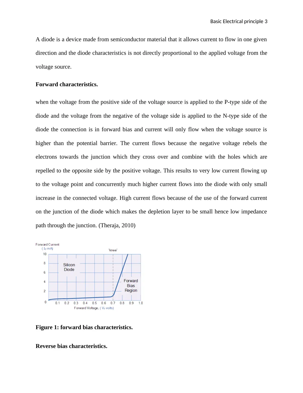
when the voltage from the positive side of the voltage source is applied to the P-type side of the
diode and the voltage from the negative of the voltage side is applied to the N-type side of the
diode the connection is in forward bias and current will only flow when the voltage source is
higher than the potential barrier. The current flows because the negative voltage rebels the
electrons towards the junction which they cross over and combine with the holes which are
repelled to the opposite side by the positive voltage. This results to very low current flowing up
to the voltage point and concurrently much higher current flows into the diode with only small
increase in the connected voltage. High current flows because of the use of the forward current
on the junction of the diode which makes the depletion layer to be small hence low impedance
path through the junction. (Theraja, 2010)
Figure 1: forward bias characteristics.
Reverse bias characteristics.
⊘ This is a preview!⊘
Do you want full access?
Subscribe today to unlock all pages.

Trusted by 1+ million students worldwide
Basic Electrical principle 4
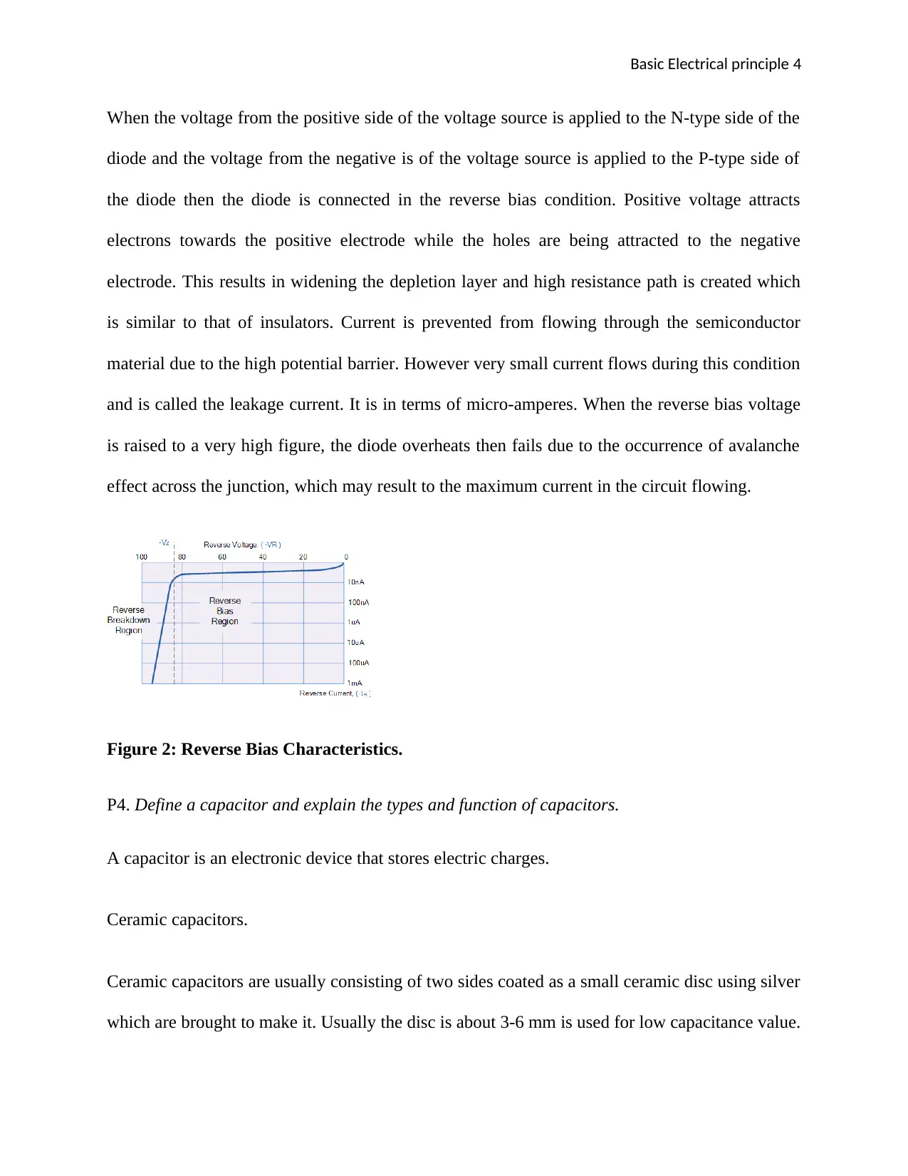
When the voltage from the positive side of the voltage source is applied to the N-type side of the
diode and the voltage from the negative is of the voltage source is applied to the P-type side of
the diode then the diode is connected in the reverse bias condition. Positive voltage attracts
electrons towards the positive electrode while the holes are being attracted to the negative
electrode. This results in widening the depletion layer and high resistance path is created which
is similar to that of insulators. Current is prevented from flowing through the semiconductor
material due to the high potential barrier. However very small current flows during this condition
and is called the leakage current. It is in terms of micro-amperes. When the reverse bias voltage
is raised to a very high figure, the diode overheats then fails due to the occurrence of avalanche
effect across the junction, which may result to the maximum current in the circuit flowing.
Figure 2: Reverse Bias Characteristics.
P4. Define a capacitor and explain the types and function of capacitors.
A capacitor is an electronic device that stores electric charges.
Ceramic capacitors.
Ceramic capacitors are usually consisting of two sides coated as a small ceramic disc using silver
which are brought to make it. Usually the disc is about 3-6 mm is used for low capacitance value.
Paraphrase This Document
Need a fresh take? Get an instant paraphrase of this document with our AI Paraphraser
Basic Electrical principle 5
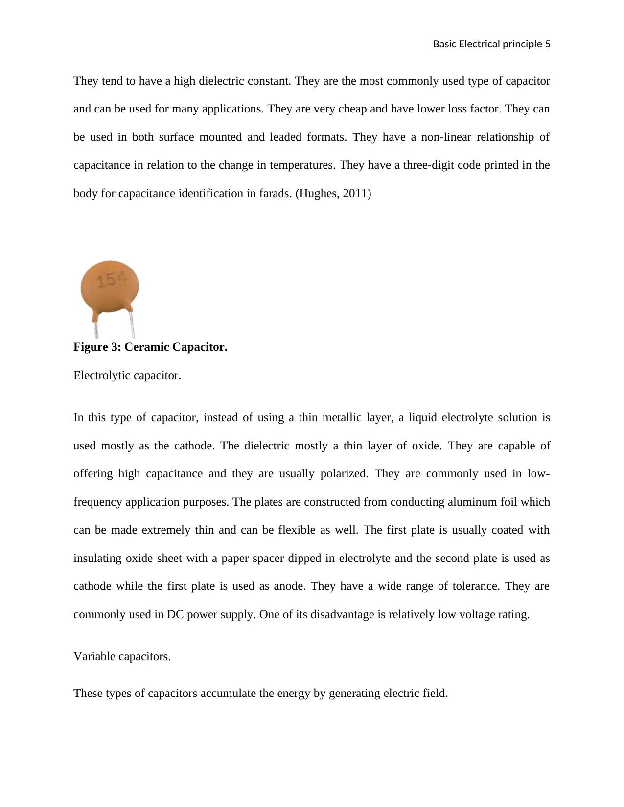
They tend to have a high dielectric constant. They are the most commonly used type of capacitor
and can be used for many applications. They are very cheap and have lower loss factor. They can
be used in both surface mounted and leaded formats. They have a non-linear relationship of
capacitance in relation to the change in temperatures. They have a three-digit code printed in the
body for capacitance identification in farads. (Hughes, 2011)
Figure 3: Ceramic Capacitor.
Electrolytic capacitor.
In this type of capacitor, instead of using a thin metallic layer, a liquid electrolyte solution is
used mostly as the cathode. The dielectric mostly a thin layer of oxide. They are capable of
offering high capacitance and they are usually polarized. They are commonly used in low-
frequency application purposes. The plates are constructed from conducting aluminum foil which
can be made extremely thin and can be flexible as well. The first plate is usually coated with
insulating oxide sheet with a paper spacer dipped in electrolyte and the second plate is used as
cathode while the first plate is used as anode. They have a wide range of tolerance. They are
commonly used in DC power supply. One of its disadvantage is relatively low voltage rating.
Variable capacitors.
These types of capacitors accumulate the energy by generating electric field.
Basic Electrical principle 6
Functions.
They are used for power supply especially those of high voltage electrolytic. To eliminate the
transient effect in the power supply.
P5. Understand the charging and discharging of a capacitor by conducting the experiment.
The capacitor is connected in series with the voltage source which is DC source and parallel with
a resistor.
When the capacitor is connected to a direct current power source, current usually flows through
the circuit and the two plates obtain equal amount and opposite charges as the difference in
potential raises to a higher value. This condition is mostly created when the capacitor is being
charged. The capacitor becomes full when the voltage of the terminal is equal with the voltage
that is supplied and the current ceases to flow in the circuit. When the supply is withdrawn, the
capacitor discharges through a resistor and the potential difference reduces gradually to zero as
current flows from the capacitor to the resistor. The product of capacitance (C) and resistance (R)
is called time constant. (Hughes, 2011)
P6. Calculate the circuit elements for a circuit consisting of three capacitors in series and in
parallel.
Capacitance connected in parallel.
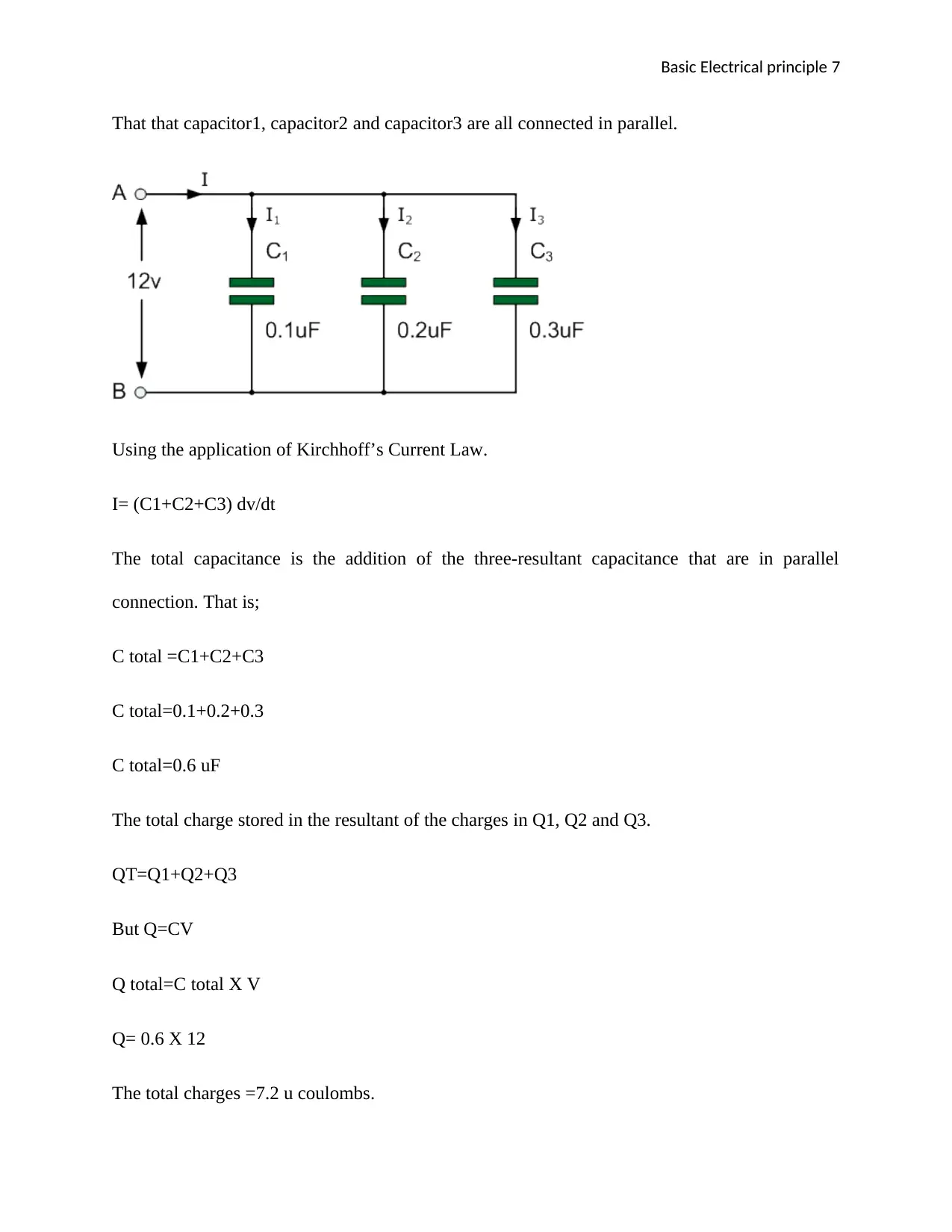
Capacitors voltages are the same as the supply voltage for the parallel connection. That means
that; (Hughes, 2011)
VC1 = VC2 = VC3 = VAB = 12V
⊘ This is a preview!⊘
Do you want full access?
Subscribe today to unlock all pages.

Trusted by 1+ million students worldwide
Basic Electrical principle 7
That that capacitor1, capacitor2 and capacitor3 are all connected in parallel.
Using the application of Kirchhoff’s Current Law.
I= (C1+C2+C3) dv/dt
The total capacitance is the addition of the three-resultant capacitance that are in parallel
connection. That is;
C total =C1+C2+C3
C total=0.1+0.2+0.3
C total=0.6 uF
The total charge stored in the resultant of the charges in Q1, Q2 and Q3.
QT=Q1+Q2+Q3
But Q=CV
Q total=C total X V
Q= 0.6 X 12
The total charges =7.2 u coulombs.
Paraphrase This Document
Need a fresh take? Get an instant paraphrase of this document with our AI Paraphraser
Basic Electrical principle 8
Capacitors in series.
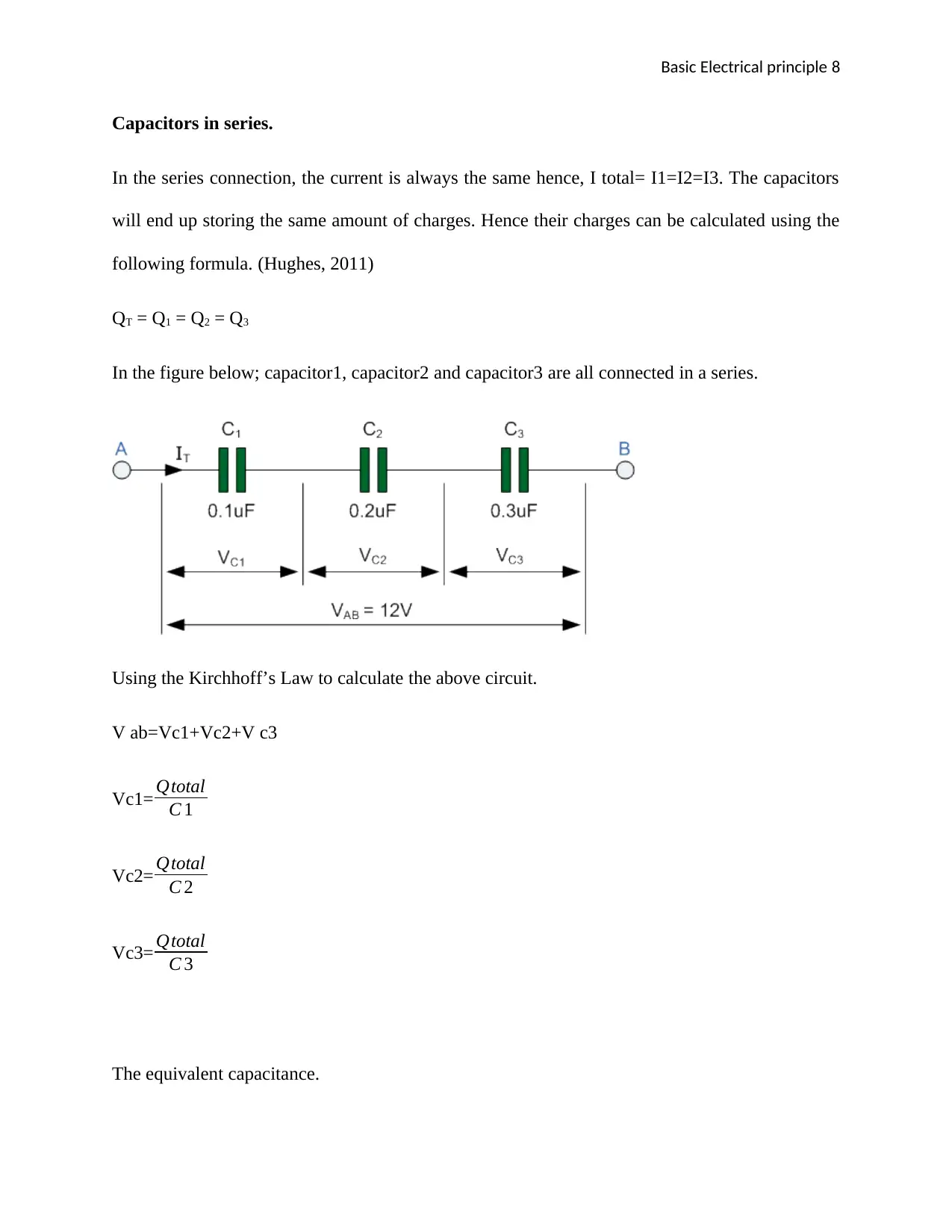
In the series connection, the current is always the same hence, I total= I1=I2=I3. The capacitors
will end up storing the same amount of charges. Hence their charges can be calculated using the
following formula. (Hughes, 2011)
QT = Q1 = Q2 = Q3
In the figure below; capacitor1, capacitor2 and capacitor3 are all connected in a series.
Using the Kirchhoff’s Law to calculate the above circuit.
V ab=Vc1+Vc2+V c3
Vc1= Qtotal
C 1
Vc2= Qtotal
C 2
Vc3= Qtotal
C 3
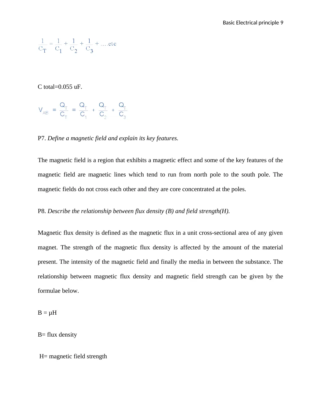
The equivalent capacitance.
Basic Electrical principle 9
C total=0.055 uF.
P7. Define a magnetic field and explain its key features.
The magnetic field is a region that exhibits a magnetic effect and some of the key features of the
magnetic field are magnetic lines which tend to run from north pole to the south pole. The
magnetic fields do not cross each other and they are core concentrated at the poles.
P8. Describe the relationship between flux density (B) and field strength(H).
Magnetic flux density is defined as the magnetic flux in a unit cross-sectional area of any given
magnet. The strength of the magnetic flux density is affected by the amount of the material
present. The intensity of the magnetic field and finally the media in between the substance. The
relationship between magnetic flux density and magnetic field strength can be given by the
formulae below.
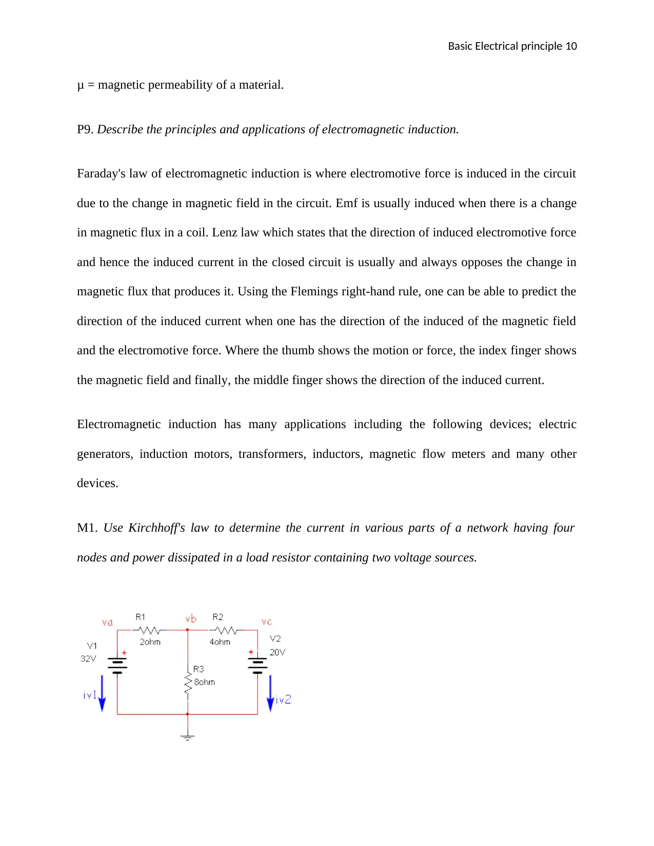
B = μH
B= flux density
H= magnetic field strength
⊘ This is a preview!⊘
Do you want full access?
Subscribe today to unlock all pages.

Trusted by 1+ million students worldwide
Basic Electrical principle 10
μ = magnetic permeability of a material.
P9. Describe the principles and applications of electromagnetic induction.
Faraday's law of electromagnetic induction is where electromotive force is induced in the circuit
due to the change in magnetic field in the circuit. Emf is usually induced when there is a change
in magnetic flux in a coil. Lenz law which states that the direction of induced electromotive force
and hence the induced current in the closed circuit is usually and always opposes the change in
magnetic flux that produces it. Using the Flemings right-hand rule, one can be able to predict the
direction of the induced current when one has the direction of the induced of the magnetic field
and the electromotive force. Where the thumb shows the motion or force, the index finger shows
the magnetic field and finally, the middle finger shows the direction of the induced current.
Electromagnetic induction has many applications including the following devices; electric
generators, induction motors, transformers, inductors, magnetic flow meters and many other
devices.
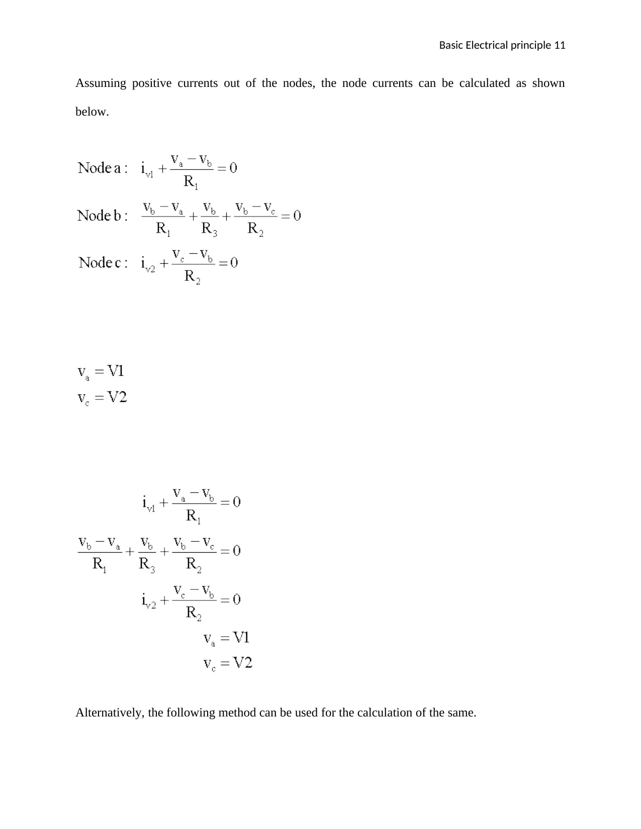
M1. Use Kirchhoff's law to determine the current in various parts of a network having four
nodes and power dissipated in a load resistor containing two voltage sources.
Paraphrase This Document
Need a fresh take? Get an instant paraphrase of this document with our AI Paraphraser
Basic Electrical principle 11
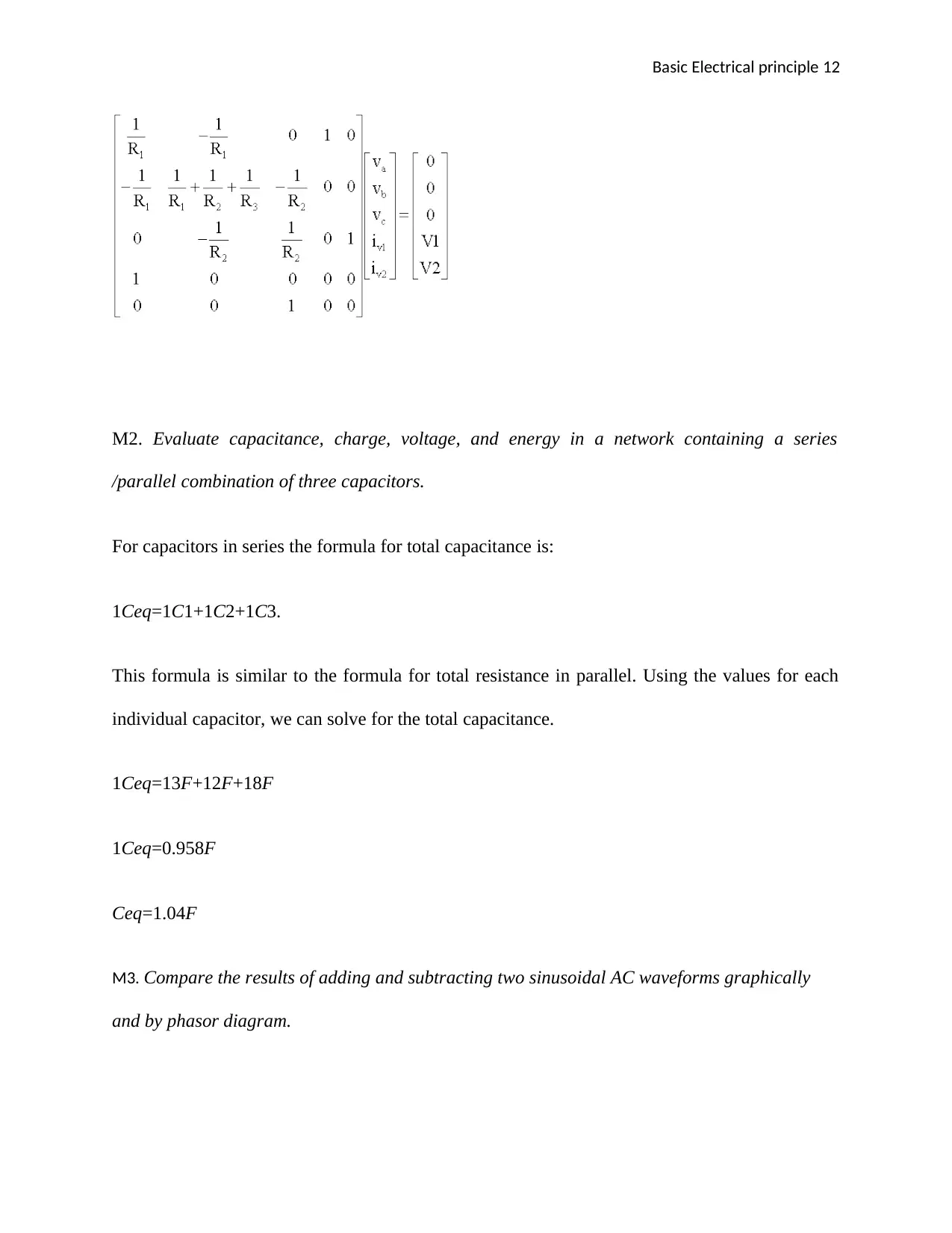
Assuming positive currents out of the nodes, the node currents can be calculated as shown
below.
Alternatively, the following method can be used for the calculation of the same.
Assuming positive currents out of the nodes, the node currents can be calculated as shown
below.
Alternatively, the following method can be used for the calculation of the same.
Basic Electrical principle 12
M2. Evaluate capacitance, charge, voltage, and energy in a network containing a series
/parallel combination of three capacitors.
For capacitors in series the formula for total capacitance is:
1Ceq=1C1+1C2+1C3.
This formula is similar to the formula for total resistance in parallel. Using the values for each
individual capacitor, we can solve for the total capacitance.
1Ceq=13F+12F+18F
1Ceq=0.958F
Ceq=1.04F
M3. Compare the results of adding and subtracting two sinusoidal AC waveforms graphically
and by phasor diagram.
⊘ This is a preview!⊘
Do you want full access?
Subscribe today to unlock all pages.

Trusted by 1+ million students worldwide
1 out of 21
Related Documents
Your All-in-One AI-Powered Toolkit for Academic Success.
+13062052269
info@desklib.com
Available 24*7 on WhatsApp / Email
![[object Object]](/_next/static/media/star-bottom.7253800d.svg)
Unlock your academic potential
Copyright © 2020–2025 A2Z Services. All Rights Reserved. Developed and managed by ZUCOL.


