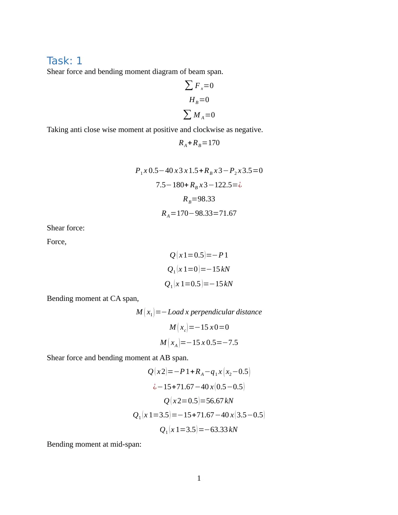
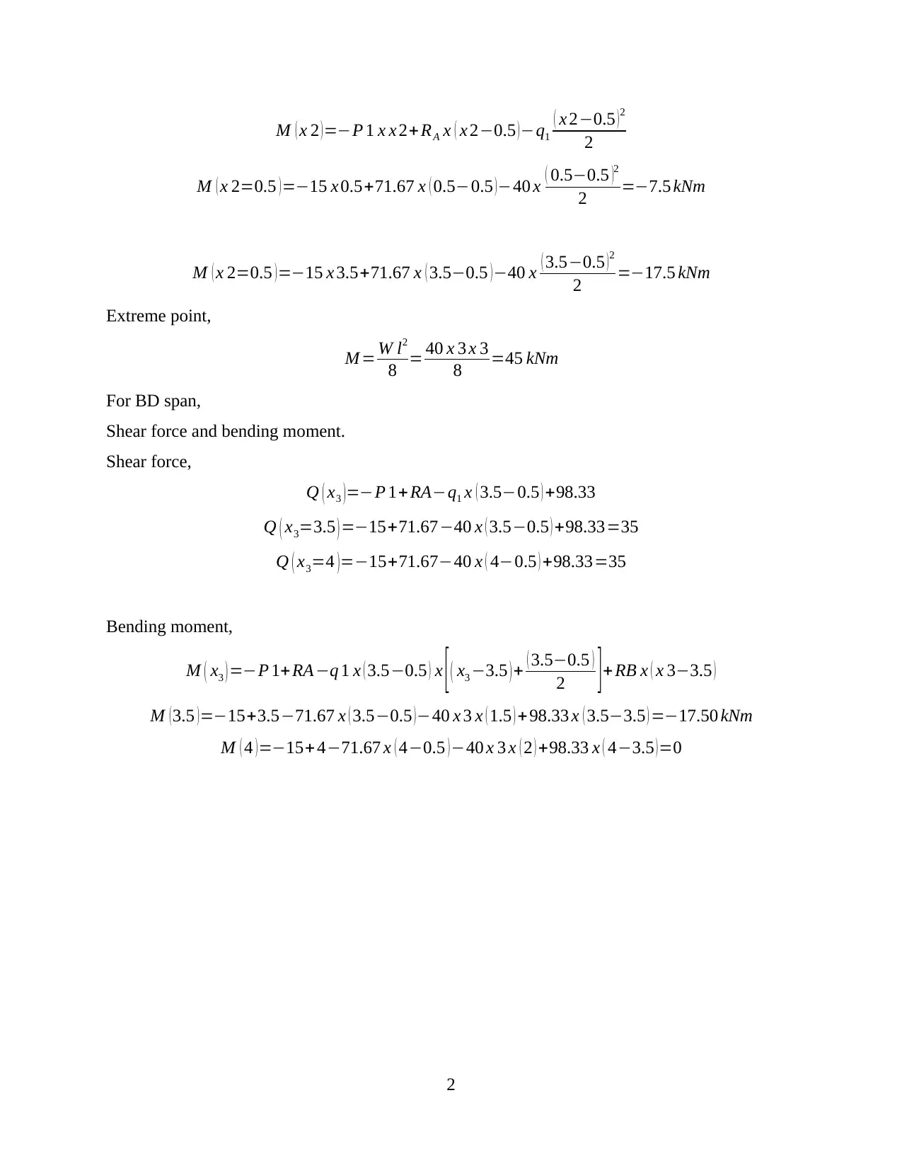
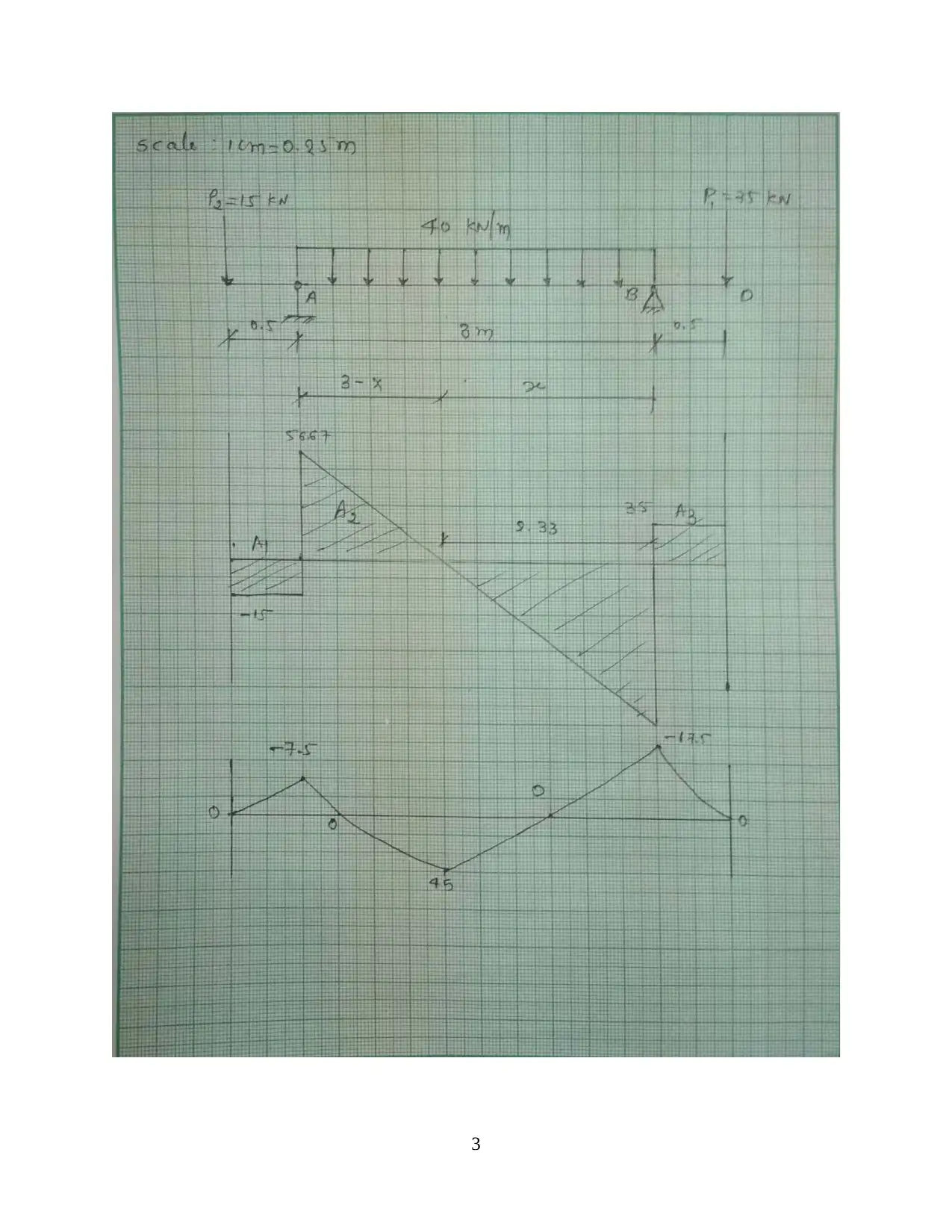
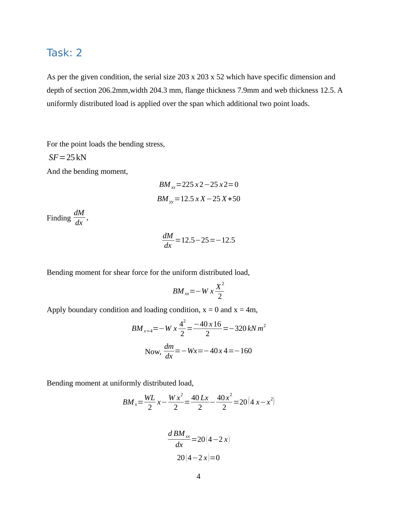
Mechanical Engineering: Shear Force and Bending Moment Diagram
VerifiedAdded on 2023/06/14
|7
|831
|164
Homework Assignment
AI Summary
This assignment provides a comprehensive analysis of beam spans, focusing on shear force and bending moment diagrams. It includes calculations for reactions, shear forces, and bending moments at various points along the beam, considering both point loads and uniformly distributed loads. Th...

Task: 1
Shear force and bending moment diagram of beam span.
∑ F x=0
HB =0
∑ M A =0
Taking anti close wise moment at positive and clockwise as negative.
RA + RB =170
P1 x 0.5−40 x 3 x 1.5+ RB x 3−P2 x 3.5=0
7.5−180+ RB x 3−122.5=¿
RB=98.33
RA =170−98.33=71.67
Shear force:
Force,
Q ( x 1=0.5 )=−P 1
Q1 ( x 1=0 ) =−15 kN
Q1 ( x 1=0.5 ) =−15 kN
Bending moment at CA span,
M ( x1 ) =−Load x perpendicular distance
M ( xc ) =−15 x 0=0
M ( xA ) =−15 x 0.5=−7.5
Shear force and bending moment at AB span.
Q ( x 2 ) =−P 1+RA −q1 x ( x2 −0.5 )
¿−15+71.67−40 x ( 0.5−0.5 )
Q ( x 2=0.5 )=56.67 kN
Q1 ( x 1=3.5 ) =−15+71.67−40 x ( 3.5−0.5 )
Q1 ( x 1=3.5 ) =−63.33 kN
Bending moment at mid-span:
1
Paraphrase This Document
Need a fresh take? Get an instant paraphrase of this document with our AI Paraphraser

M ( x 2 )=−P 1 x x 2+ RA x ( x 2−0.5 )−q1
( x 2−0.5 )2
2
M ( x 2=0.5 ) =−15 x 0.5+71.67 x ( 0.5−0.5 ) −40 x ( 0.5−0.5 )2
2 =−7.5 kNm
M ( x 2=0.5 )=−15 x 3.5+71.67 x ( 3.5−0.5 )−40 x ( 3.5−0.5 )2
2 =−17.5 kNm
Extreme point,
M = W l2
8 = 40 x 3 x 3
8 =45 kNm
For BD span,
Shear force and bending moment.
Shear force,
Q ( x3 )=−P 1+RA−q1 x ( 3.5−0.5 ) +98.33
Q ( x3=3.5 ) =−15+71.67−40 x ( 3.5−0.5 ) +98.33=35
Q ( x3=4 ) =−15+71.67−40 x ( 4−0.5 ) +98.33=35
Bending moment,
M ( x3 ) =−P 1+ RA−q 1 x ( 3.5−0.5 ) x [ ( x3 −3.5 ) + ( 3.5−0.5 )
2 ] + RB x ( x 3−3.5 )
M (3.5 )=−15+3.5−71.67 x ( 3.5−0.5 )−40 x 3 x ( 1.5 ) +98.33 x ( 3.5−3.5 ) =−17.50 kNm
M ( 4 )=−15+ 4−71.67 x ( 4−0.5 )−40 x 3 x ( 2 ) +98.33 x ( 4−3.5 )=0
2

3
⊘ This is a preview!⊘
Do you want full access?
Subscribe today to unlock all pages.

Trusted by 1+ million students worldwide

Task: 2
As per the given condition, the serial size 203 x 203 x 52 which have specific dimension and
depth of section 206.2mm,width 204.3 mm, flange thickness 7.9mm and web thickness 12.5. A
uniformly distributed load is applied over the span which additional two point loads.
For the point loads the bending stress,
SF=25 kN
And the bending moment,
BM xx=225 x 2−25 x 2=0
BM yy =12.5 x X −25 X +50
Finding dM
dx ,
dM
dx =12.5−25=−12.5
Bending moment for shear force for the uniform distributed load,
BM xx=−W x X 2
2
Apply boundary condition and loading condition, x = 0 and x = 4m,
BM x=4=−W x 42
2 =−40 x 16
2 =−320 kN m2
Now, dm
dx =−Wx=−40 x 4=−160
Bending moment at uniformly distributed load,
BM x=WL
2 x− W x2
2 = 40 Lx
2 − 40 x2
2 =20 ( 4 x−x2 )
d BM xx
dx =20 ( 4−2 x )
20 ( 4−2 x ) =0
4
Paraphrase This Document
Need a fresh take? Get an instant paraphrase of this document with our AI Paraphraser

x=2 m
The point of contra-flexure obtained by,
−63.33−15 ( x +0.5 ) −35 x X x X
2
Differential above equation by x,
dm
dx =15 x−7.5−17.5 x2
15−35 x=0
x=2.33 m
As per shown in diagram,
Y = A 1 Y 1+ A 2 Y 2+ A 3 Y 3
A 1+ A 2+ A 3
¿
204.3 x 12.5 x ( 106.8+12.5+ 12.5
2 ) + ( 106.8 ) ( 7.9 ) ( 160.8
2 +12.5 ) + ( 204.3 x 12.5 x 6.25 )
2 x 204.3 x 12.5+160.8 x 12.5
Y =83.24 mm
I =INA + A h2
Iy 1=2 x [ 1
12 ( 204.3 ) ( 12.5 ) 3 + ( 204.3 x 12.5 ) ( 86.65 ) 3
] + 1
12 ( 160.8 ) ( 7.9 ) 3=¿
¿ 3322942056.0909375+6606.7226
¿ 3322948662.8135375
Iy 1=3.322 x 109 mm4
M
I = σ
Y
σ = MY
I = 45 x 83.24 x 106
3.322 x 109 =1127 N /mm2
5

6
⊘ This is a preview!⊘
Do you want full access?
Subscribe today to unlock all pages.

Trusted by 1+ million students worldwide

Task: 3
Slenderness ratio k = l
r =185.8
5.18 =35.86
Value of slenderness is less than 200 which is safe for the design point of view. If the slenderness
value greater than 200 so that there are higher chance to get failed.
This I section beam is short because of safe operation with respect to y-directional length.
7
1 out of 7
Related Documents

Your All-in-One AI-Powered Toolkit for Academic Success.
+13062052269
info@desklib.com
Available 24*7 on WhatsApp / Email
Unlock your academic potential
© 2024 | Zucol Services PVT LTD | All rights reserved.