Bending Moments & Shear Forces with Beam Design Considerations - Desklib
VerifiedAdded on 2022/11/13
|26
|2873
|174
AI Summary
This document discusses Bending Moments & Shear Forces with Beam Design Considerations in Structural Design. It includes calculations for deflection, axial load carrying capacity of steel and reinforced concrete columns, and methods of supports for structures. It also covers the concept of slenderness ratio and statutory requirements for structural design. The document includes solved assignments, essays, and dissertations related to HNCB 20- Principles of Structural Design.
Contribute Materials
Your contribution can guide someone’s learning journey. Share your
documents today.
BENDING MOMENTS & SHEAR FORCES WITH BEAM
DESIGN CONSIDERATIONS
HNCB 20- PRINCIPLES OF STRUCTURAL DESIGN
1
DESIGN CONSIDERATIONS
HNCB 20- PRINCIPLES OF STRUCTURAL DESIGN
1
Secure Best Marks with AI Grader
Need help grading? Try our AI Grader for instant feedback on your assignments.
Table of Contents
Task 1...............................................................................................................................................4
Task 2.............................................................................................................................................16
Task 3.............................................................................................................................................20
Task 4.............................................................................................................................................22
Reference list.................................................................................................................................26
2
Task 1
1 (A)
A
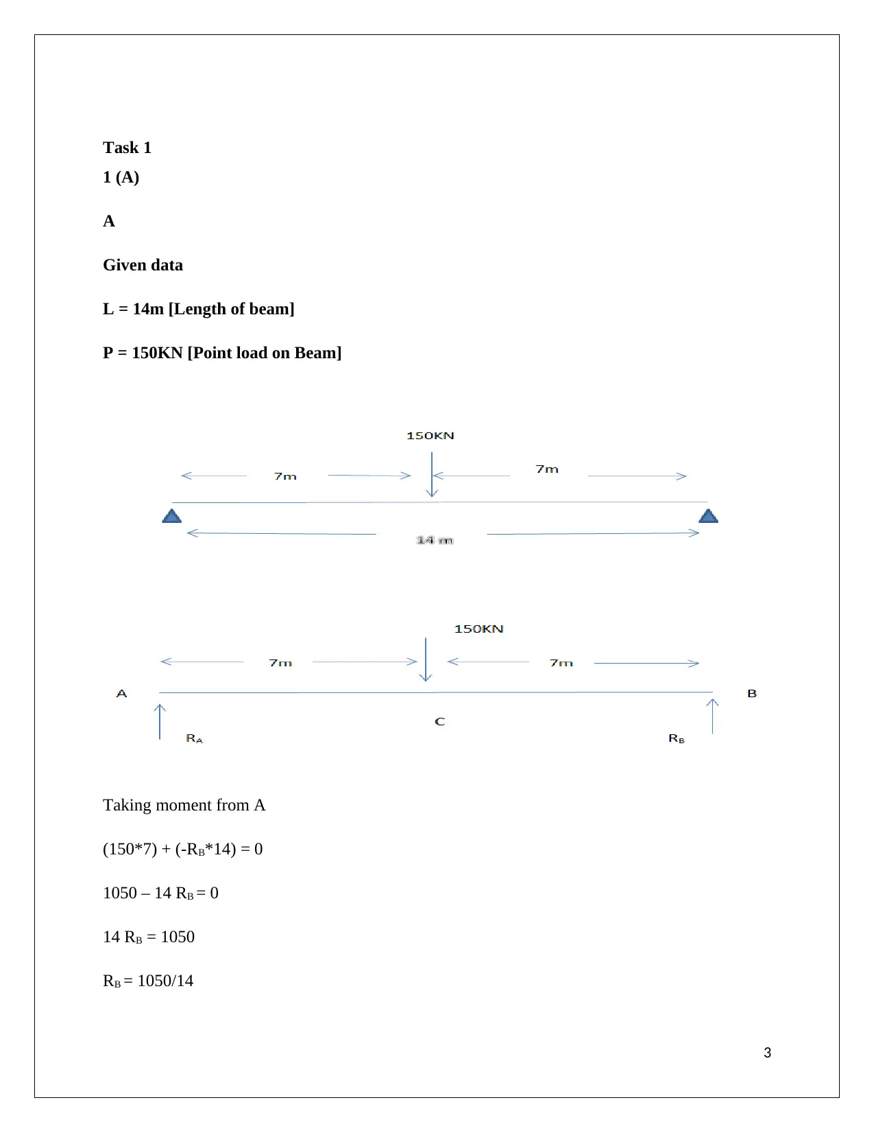
Given data
L = 14m [Length of beam]
P = 150KN [Point load on Beam]
Taking moment from A
(150*7) + (-RB*14) = 0
1050 – 14 RB = 0
14 RB = 1050
RB = 1050/14
3
1 (A)
A
Given data
L = 14m [Length of beam]
P = 150KN [Point load on Beam]
Taking moment from A
(150*7) + (-RB*14) = 0
1050 – 14 RB = 0
14 RB = 1050
RB = 1050/14
3
RB = 75 ------------- [1]
Summation of upward force and downward force
RA – 150 +RB = 0
RA = 150 – 75
RA = 75 KN -------- [2]
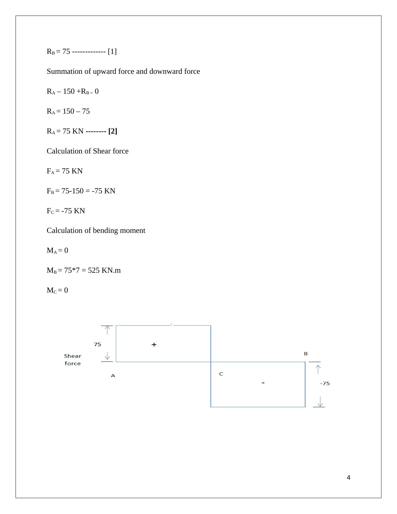
Calculation of Shear force
FA = 75 KN
FB = 75-150 = -75 KN
FC = -75 KN
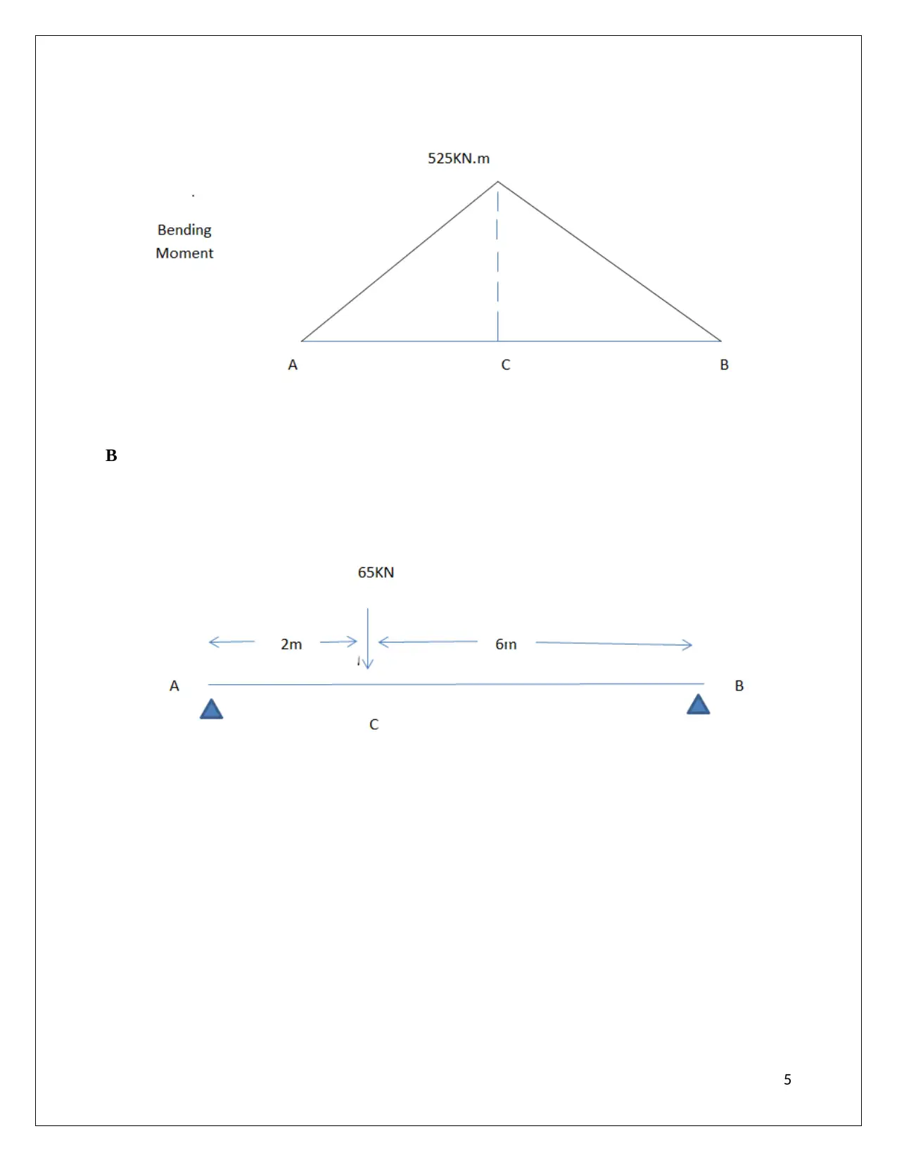
Calculation of bending moment
MA = 0
MB = 75*7 = 525 KN.m
MC = 0
4
Summation of upward force and downward force
RA – 150 +RB = 0
RA = 150 – 75
RA = 75 KN -------- [2]
Calculation of Shear force
FA = 75 KN
FB = 75-150 = -75 KN
FC = -75 KN
Calculation of bending moment
MA = 0
MB = 75*7 = 525 KN.m
MC = 0
4
Secure Best Marks with AI Grader
Need help grading? Try our AI Grader for instant feedback on your assignments.
B
5
5
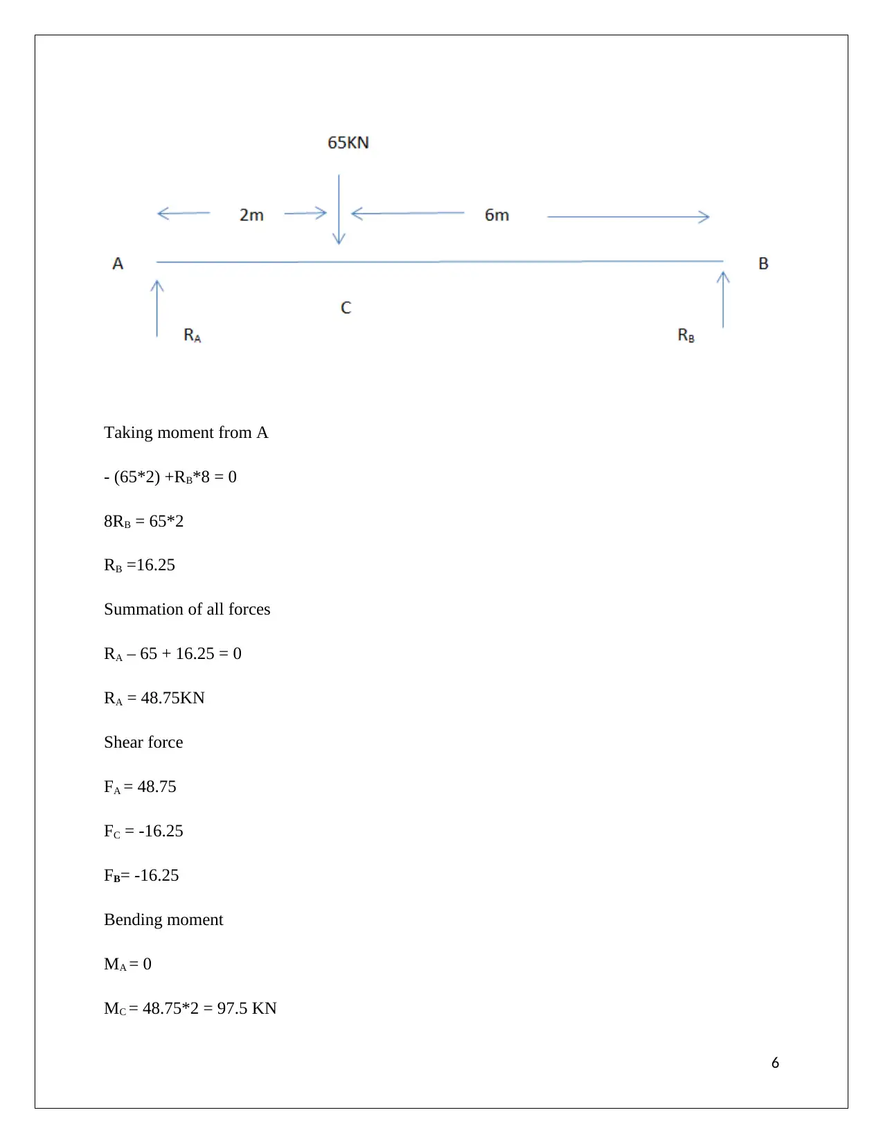
Taking moment from A
- (65*2) +RB*8 = 0
8RB = 65*2
RB =16.25
Summation of all forces
RA – 65 + 16.25 = 0
RA = 48.75KN
Shear force
FA = 48.75
FC = -16.25
FB= -16.25
Bending moment
MA = 0
MC = 48.75*2 = 97.5 KN
6
- (65*2) +RB*8 = 0
8RB = 65*2
RB =16.25
Summation of all forces
RA – 65 + 16.25 = 0
RA = 48.75KN
Shear force
FA = 48.75
FC = -16.25
FB= -16.25
Bending moment
MA = 0
MC = 48.75*2 = 97.5 KN
6
MB =0
C
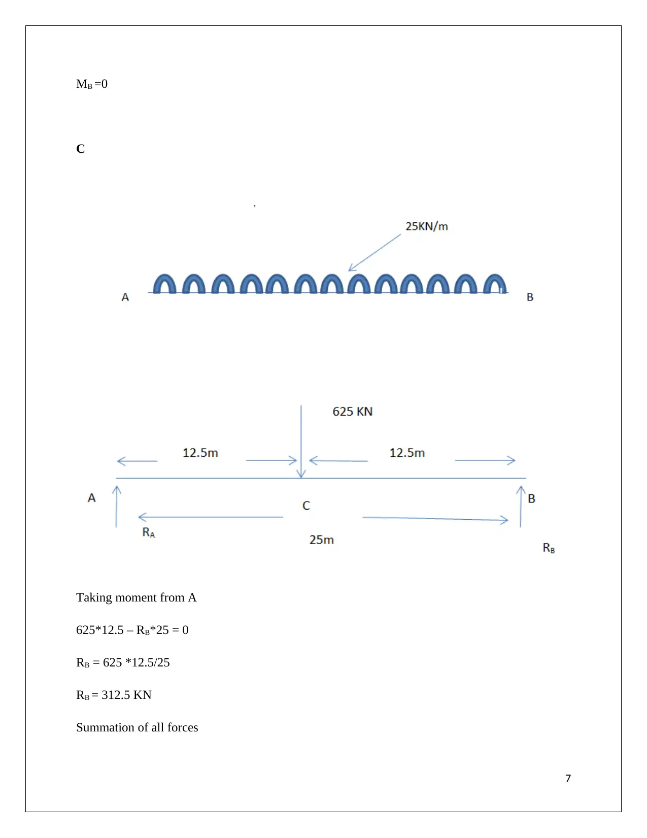
Taking moment from A
625*12.5 – RB*25 = 0
RB = 625 *12.5/25
RB = 312.5 KN
Summation of all forces
7
C
Taking moment from A
625*12.5 – RB*25 = 0
RB = 625 *12.5/25
RB = 312.5 KN
Summation of all forces
7
Paraphrase This Document
Need a fresh take? Get an instant paraphrase of this document with our AI Paraphraser
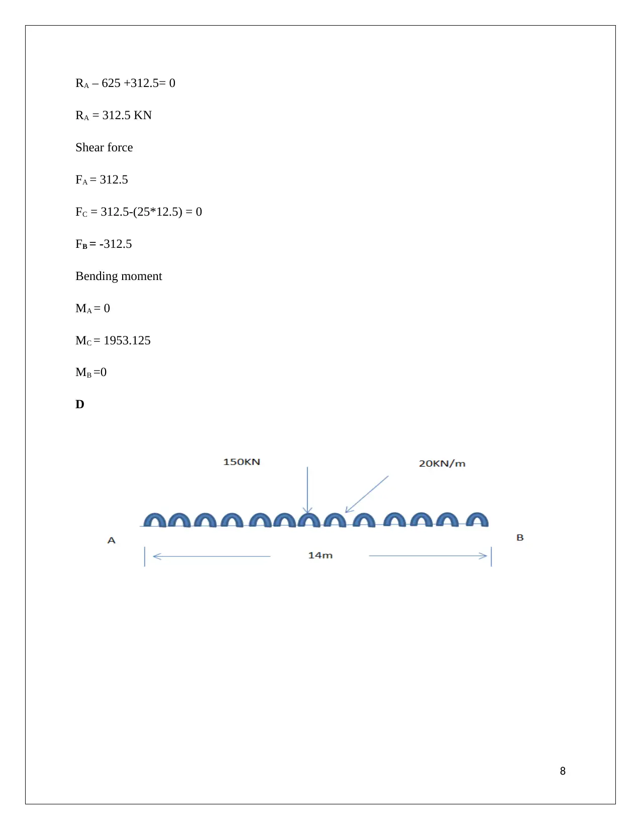
RA – 625 +312.5= 0
RA = 312.5 KN
Shear force
FA = 312.5
FC = 312.5-(25*12.5) = 0
FB = -312.5
Bending moment
MA = 0
MC = 1953.125
MB =0
D
8
RA = 312.5 KN
Shear force
FA = 312.5
FC = 312.5-(25*12.5) = 0
FB = -312.5
Bending moment
MA = 0
MC = 1953.125
MB =0
D
8
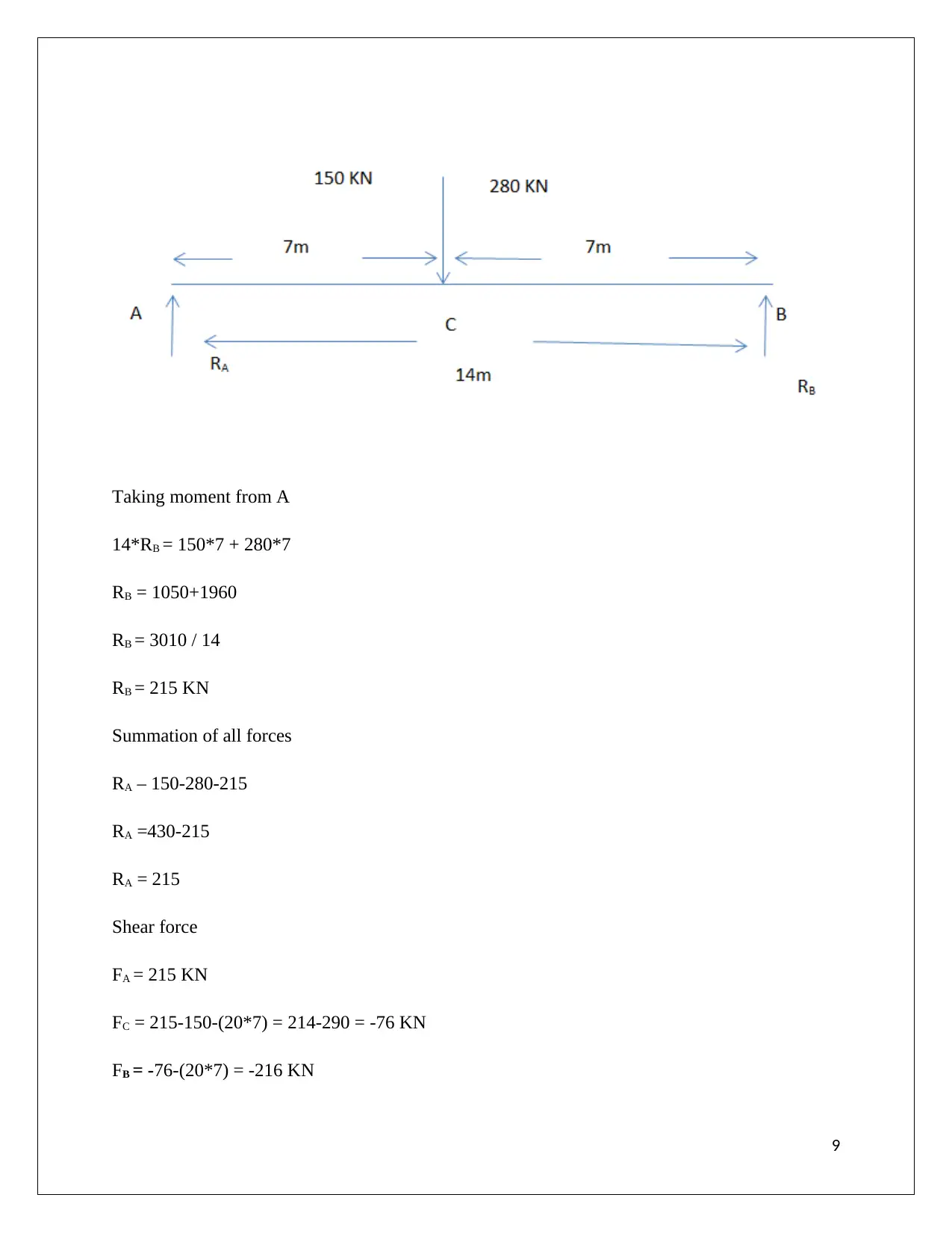
Taking moment from A
14*RB = 150*7 + 280*7
RB = 1050+1960
RB = 3010 / 14
RB = 215 KN
Summation of all forces
RA – 150-280-215
RA =430-215
RA = 215
Shear force
FA = 215 KN
FC = 215-150-(20*7) = 214-290 = -76 KN
FB = -76-(20*7) = -216 KN
9
14*RB = 150*7 + 280*7
RB = 1050+1960
RB = 3010 / 14
RB = 215 KN
Summation of all forces
RA – 150-280-215
RA =430-215
RA = 215
Shear force
FA = 215 KN
FC = 215-150-(20*7) = 214-290 = -76 KN
FB = -76-(20*7) = -216 KN
9
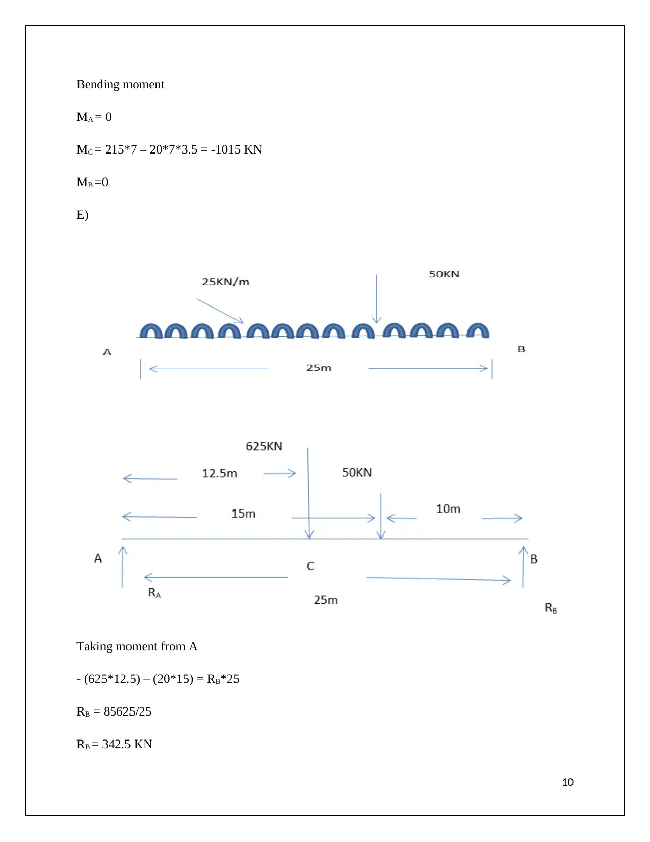
Bending moment
MA = 0
MC = 215*7 – 20*7*3.5 = -1015 KN
MB =0
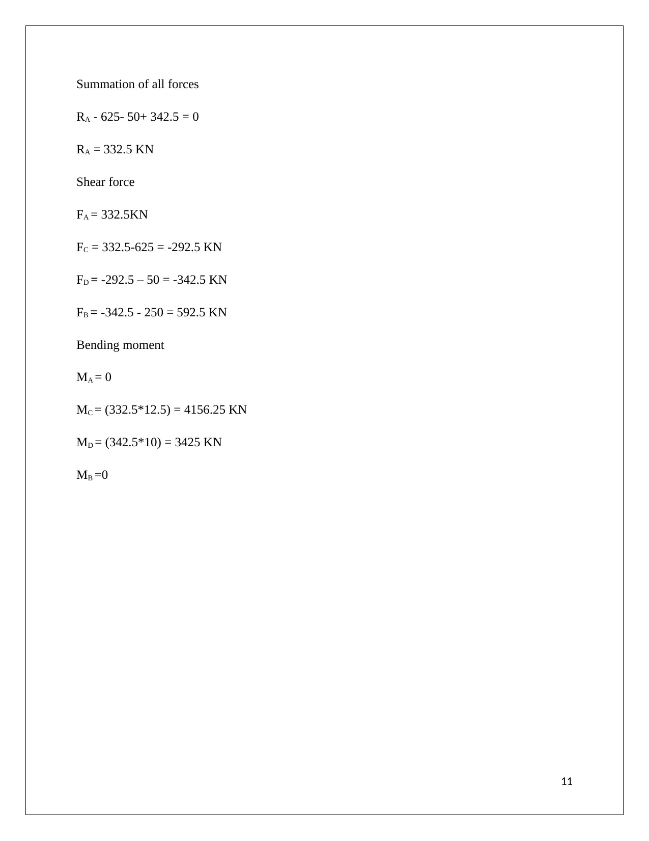
E)
Taking moment from A
- (625*12.5) – (20*15) = RB*25
RB = 85625/25
RB = 342.5 KN
10
MA = 0
MC = 215*7 – 20*7*3.5 = -1015 KN
MB =0
E)
Taking moment from A
- (625*12.5) – (20*15) = RB*25
RB = 85625/25
RB = 342.5 KN
10
Secure Best Marks with AI Grader
Need help grading? Try our AI Grader for instant feedback on your assignments.
Summation of all forces
RA - 625- 50+ 342.5 = 0
RA = 332.5 KN
Shear force
FA = 332.5KN
FC = 332.5-625 = -292.5 KN
FD = -292.5 – 50 = -342.5 KN
FB = -342.5 - 250 = 592.5 KN
Bending moment
MA = 0
MC = (332.5*12.5) = 4156.25 KN
MD = (342.5*10) = 3425 KN
MB =0
11
RA - 625- 50+ 342.5 = 0
RA = 332.5 KN
Shear force
FA = 332.5KN
FC = 332.5-625 = -292.5 KN
FD = -292.5 – 50 = -342.5 KN
FB = -342.5 - 250 = 592.5 KN
Bending moment
MA = 0
MC = (332.5*12.5) = 4156.25 KN
MD = (342.5*10) = 3425 KN
MB =0
11
Task 1 (B)
Statutory requirements are needed consider vigilantly during structural design so that potential
risks and issues can be minimized as far as possible. The first requirement is planning permission
that implies that legitimate steps have been undertaken especially in construction management.
On the contrary, shear stress and bend moment are essential components of structural design
within construction sites that reduce the risk of failure as far as possible
(Connect.bim360.autodesk.com, 2019). In construction, the permission from ministry, local
government and building regulatory are important to make sure risk of failure can be minimized
eventually.
Task 1 (C)
Dead Loads for common Residential construction
Construction option Load
Roof construction 15psf
Floor construction 10psf2
Wall construction 6Psf
Foundation construction 75psf
Table 1: Dead Loads for common Residential construction
Live loads for residential construction
Application Uniform load Concentrated load
Roof 15 psf 250 lbs
Attic 10 psf 250 lbs
Floors 20 psf 250 lbs
Decks 40 psf 300 lbs
Balconies 60 psf 300 lbs
Stairs 40 psf 300 lbs
Guards and handrails 20 psf 300 lbs
Table 2: Live loads for residential construction
Minimum imposed loads
12
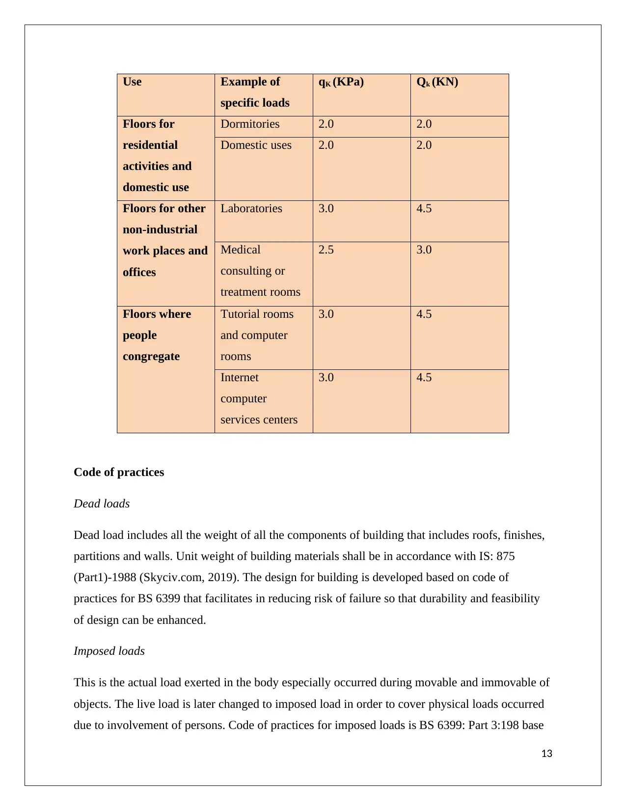
Use Example of
specific loads
qK (KPa) Qk (KN)
Floors for
residential
activities and
domestic use
Dormitories 2.0 2.0
Domestic uses 2.0 2.0
Floors for other
non-industrial
work places and
offices
Laboratories 3.0 4.5
Medical
consulting or
treatment rooms
2.5 3.0
Floors where
people
congregate
Tutorial rooms
and computer
rooms
3.0 4.5
Internet
computer
services centers
3.0 4.5
Code of practices
Dead loads
Dead load includes all the weight of all the components of building that includes roofs, finishes,
partitions and walls. Unit weight of building materials shall be in accordance with IS: 875
(Part1)-1988 (Skyciv.com, 2019). The design for building is developed based on code of
practices for BS 6399 that facilitates in reducing risk of failure so that durability and feasibility
of design can be enhanced.
Imposed loads
This is the actual load exerted in the body especially occurred during movable and immovable of
objects. The live load is later changed to imposed load in order to cover physical loads occurred
due to involvement of persons. Code of practices for imposed loads is BS 6399: Part 3:198 base
13
Paraphrase This Document
Need a fresh take? Get an instant paraphrase of this document with our AI Paraphraser
on British standards so that contribution of all loads can be include in the design that increase the
feasibility of developed design.
Task 1 (D)
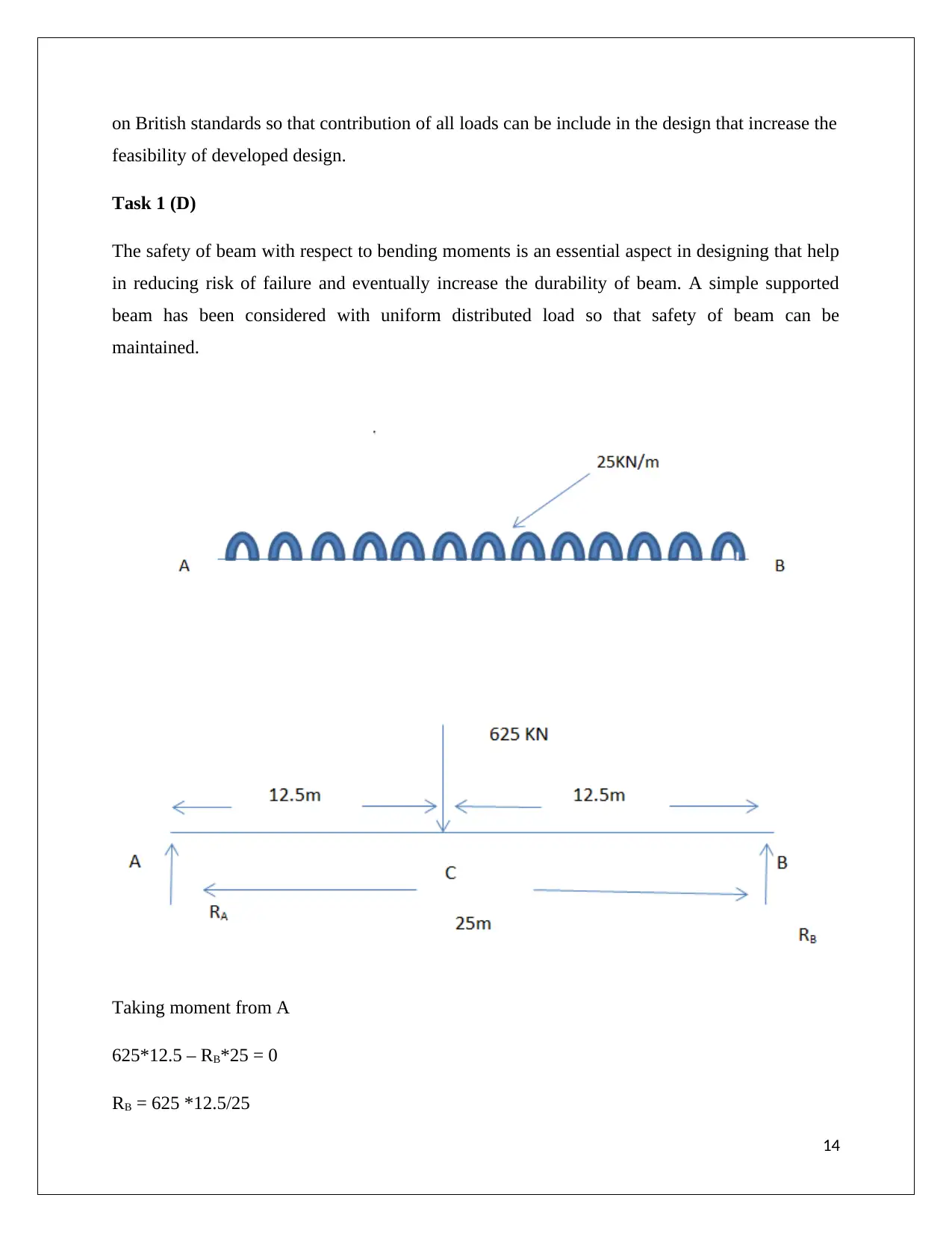
The safety of beam with respect to bending moments is an essential aspect in designing that help
in reducing risk of failure and eventually increase the durability of beam. A simple supported
beam has been considered with uniform distributed load so that safety of beam can be
maintained.
Taking moment from A
625*12.5 – RB*25 = 0
RB = 625 *12.5/25
14
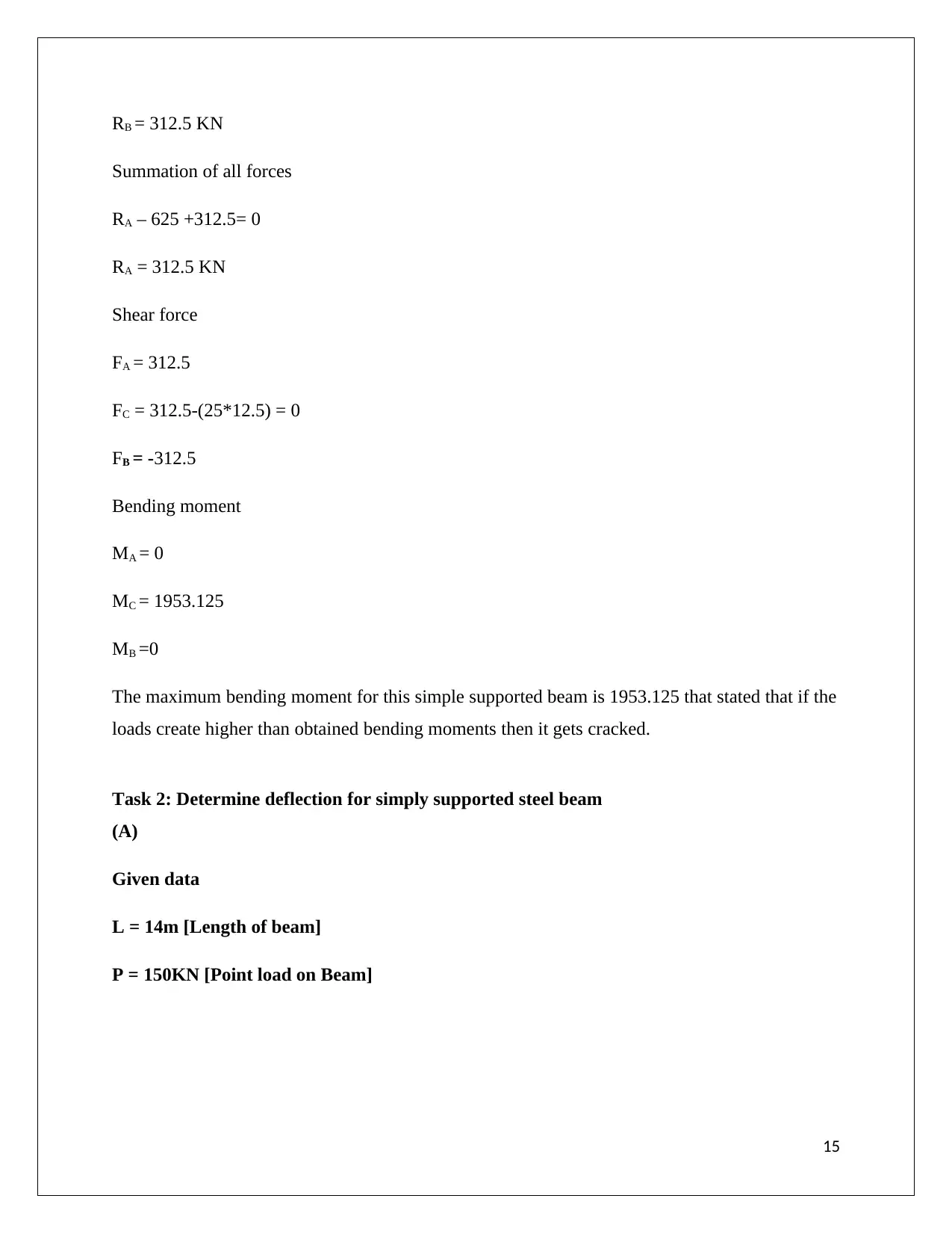
RB = 312.5 KN
Summation of all forces
RA – 625 +312.5= 0
RA = 312.5 KN
Shear force
FA = 312.5
FC = 312.5-(25*12.5) = 0
FB = -312.5
Bending moment
MA = 0
MC = 1953.125
MB =0
The maximum bending moment for this simple supported beam is 1953.125 that stated that if the
loads create higher than obtained bending moments then it gets cracked.
Task 2: Determine deflection for simply supported steel beam
(A)
Given data
L = 14m [Length of beam]
P = 150KN [Point load on Beam]
15
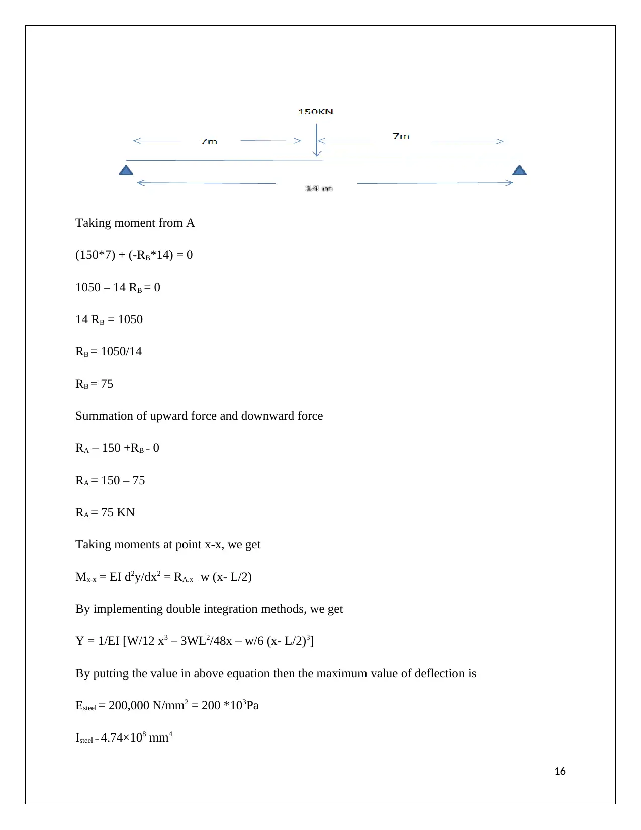
Taking moment from A
(150*7) + (-RB*14) = 0
1050 – 14 RB = 0
14 RB = 1050
RB = 1050/14
RB = 75
Summation of upward force and downward force
RA – 150 +RB = 0
RA = 150 – 75
RA = 75 KN
Taking moments at point x-x, we get
Mx-x = EI d2y/dx2 = RA.x – w (x- L/2)
By implementing double integration methods, we get
Y = 1/EI [W/12 x3 – 3WL2/48x – w/6 (x- L/2)3]
By putting the value in above equation then the maximum value of deflection is
Esteel = 200,000 N/mm2 = 200 *103Pa
Isteel = 4.74×108 mm4
16
Secure Best Marks with AI Grader
Need help grading? Try our AI Grader for instant feedback on your assignments.
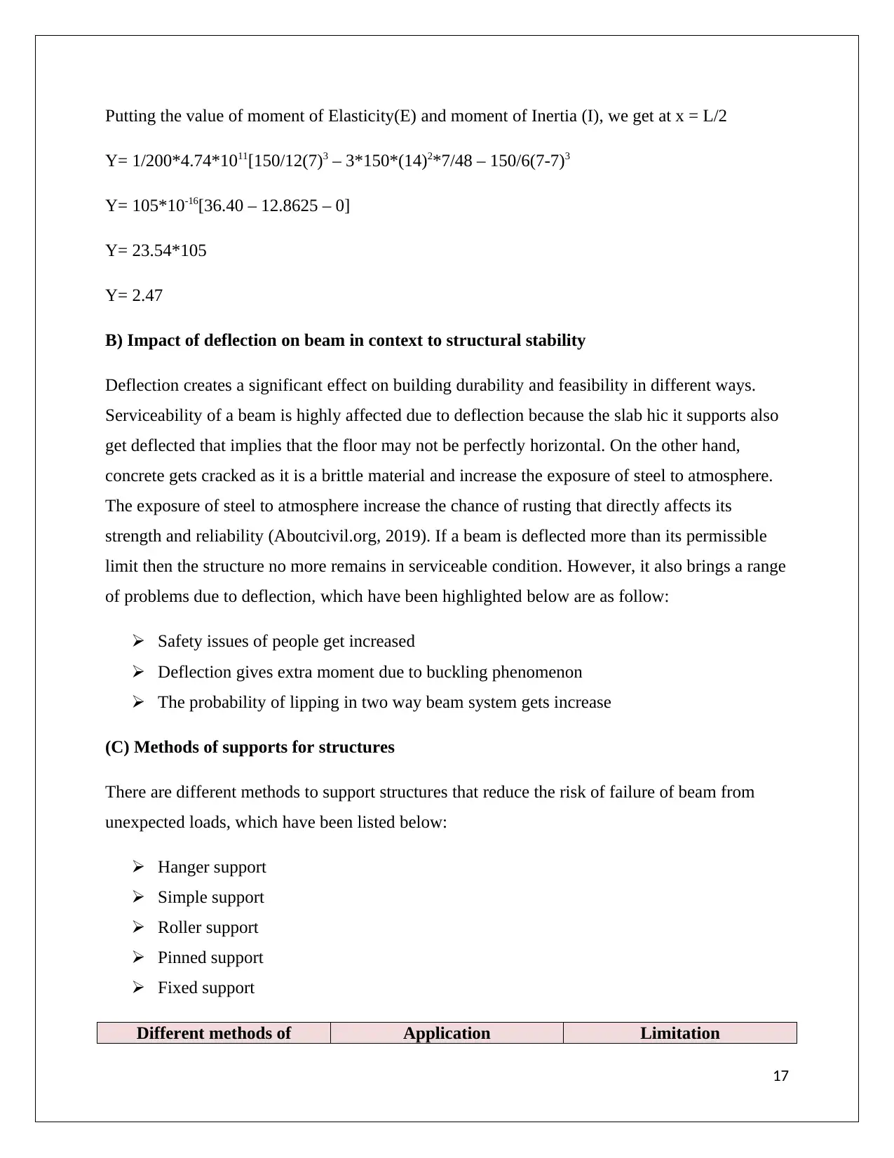
Putting the value of moment of Elasticity(E) and moment of Inertia (I), we get at x = L/2
Y= 1/200*4.74*1011[150/12(7)3 – 3*150*(14)2*7/48 – 150/6(7-7)3
Y= 105*10-16[36.40 – 12.8625 – 0]
Y= 23.54*105
Y= 2.47
B) Impact of deflection on beam in context to structural stability
Deflection creates a significant effect on building durability and feasibility in different ways.
Serviceability of a beam is highly affected due to deflection because the slab hic it supports also
get deflected that implies that the floor may not be perfectly horizontal. On the other hand,
concrete gets cracked as it is a brittle material and increase the exposure of steel to atmosphere.
The exposure of steel to atmosphere increase the chance of rusting that directly affects its
strength and reliability (Aboutcivil.org, 2019). If a beam is deflected more than its permissible
limit then the structure no more remains in serviceable condition. However, it also brings a range
of problems due to deflection, which have been highlighted below are as follow:
Safety issues of people get increased
Deflection gives extra moment due to buckling phenomenon
The probability of lipping in two way beam system gets increase
(C) Methods of supports for structures
There are different methods to support structures that reduce the risk of failure of beam from
unexpected loads, which have been listed below:
Hanger support
Simple support
Roller support
Pinned support
Fixed support
Different methods of Application Limitation
17
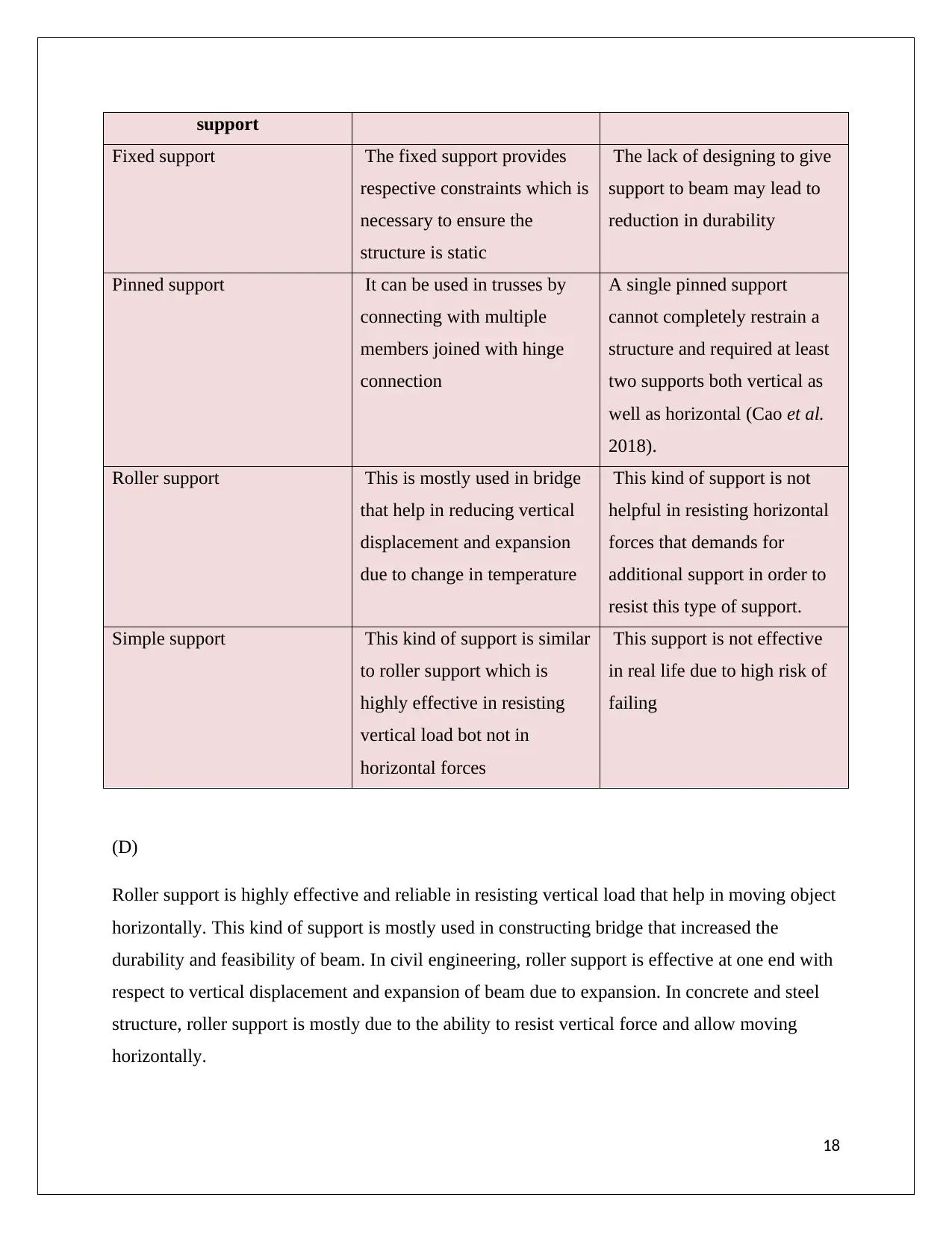
support
Fixed support The fixed support provides
respective constraints which is
necessary to ensure the
structure is static
The lack of designing to give
support to beam may lead to
reduction in durability
Pinned support It can be used in trusses by
connecting with multiple
members joined with hinge
connection
A single pinned support
cannot completely restrain a
structure and required at least
two supports both vertical as
well as horizontal (Cao et al.
2018).
Roller support This is mostly used in bridge
that help in reducing vertical
displacement and expansion
due to change in temperature
This kind of support is not
helpful in resisting horizontal
forces that demands for
additional support in order to
resist this type of support.
Simple support This kind of support is similar
to roller support which is
highly effective in resisting
vertical load bot not in
horizontal forces
This support is not effective
in real life due to high risk of
failing
(D)
Roller support is highly effective and reliable in resisting vertical load that help in moving object
horizontally. This kind of support is mostly used in constructing bridge that increased the
durability and feasibility of beam. In civil engineering, roller support is effective at one end with
respect to vertical displacement and expansion of beam due to expansion. In concrete and steel
structure, roller support is mostly due to the ability to resist vertical force and allow moving
horizontally.
18
Task 3
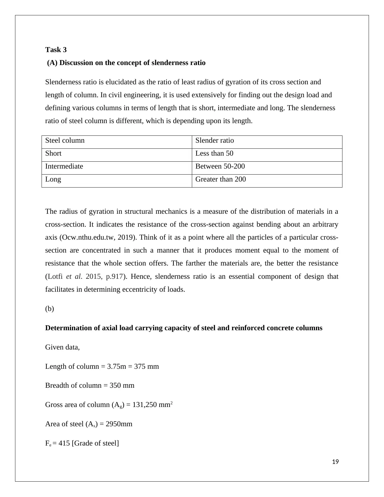
(A) Discussion on the concept of slenderness ratio
Slenderness ratio is elucidated as the ratio of least radius of gyration of its cross section and
length of column. In civil engineering, it is used extensively for finding out the design load and
defining various columns in terms of length that is short, intermediate and long. The slenderness
ratio of steel column is different, which is depending upon its length.
Steel column Slender ratio
Short Less than 50
Intermediate Between 50-200
Long Greater than 200
The radius of gyration in structural mechanics is a measure of the distribution of materials in a
cross-section. It indicates the resistance of the cross-section against bending about an arbitrary
axis (Ocw.nthu.edu.tw, 2019). Think of it as a point where all the particles of a particular cross-
section are concentrated in such a manner that it produces moment equal to the moment of
resistance that the whole section offers. The farther the materials are, the better the resistance
(Lotfi et al. 2015, p.917). Hence, slenderness ratio is an essential component of design that
facilitates in determining eccentricity of loads.
(b)
Determination of axial load carrying capacity of steel and reinforced concrete columns
Given data,
Length of column = 3.75m = 375 mm
Breadth of column = 350 mm
Gross area of column (Ag) = 131,250 mm2
Area of steel (As) = 2950mm
Fe = 415 [Grade of steel]
19
Paraphrase This Document
Need a fresh take? Get an instant paraphrase of this document with our AI Paraphraser
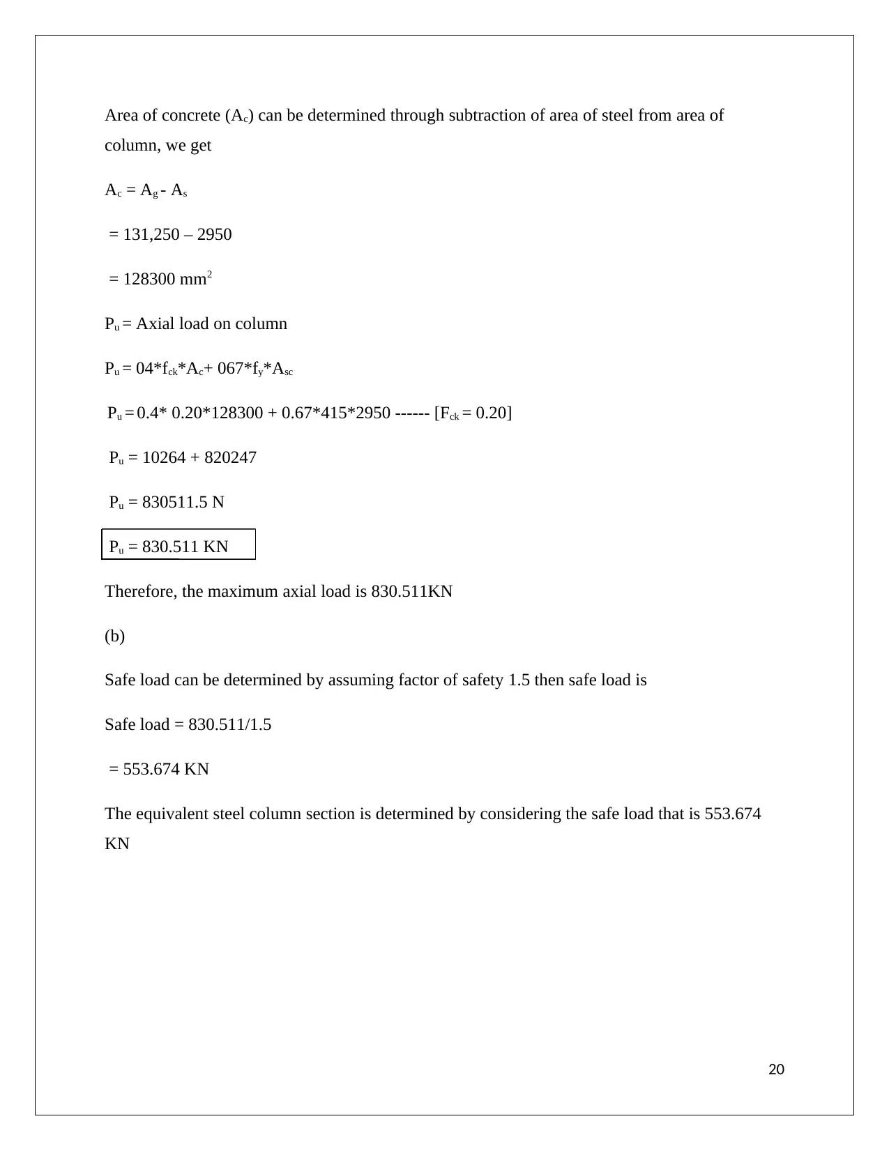
Area of concrete (Ac) can be determined through subtraction of area of steel from area of
column, we get
Ac = Ag - As
= 131,250 – 2950
= 128300 mm2
Pu = Axial load on column
Pu = 04*fck*Ac+ 067*fy*Asc
Pu = 0.4* 0.20*128300 + 0.67*415*2950 ------ [Fck = 0.20]
Pu = 10264 + 820247
Pu = 830511.5 N
Pu = 830.511 KN
Therefore, the maximum axial load is 830.511KN
(b)
Safe load can be determined by assuming factor of safety 1.5 then safe load is
Safe load = 830.511/1.5
= 553.674 KN
The equivalent steel column section is determined by considering the safe load that is 553.674
KN
20
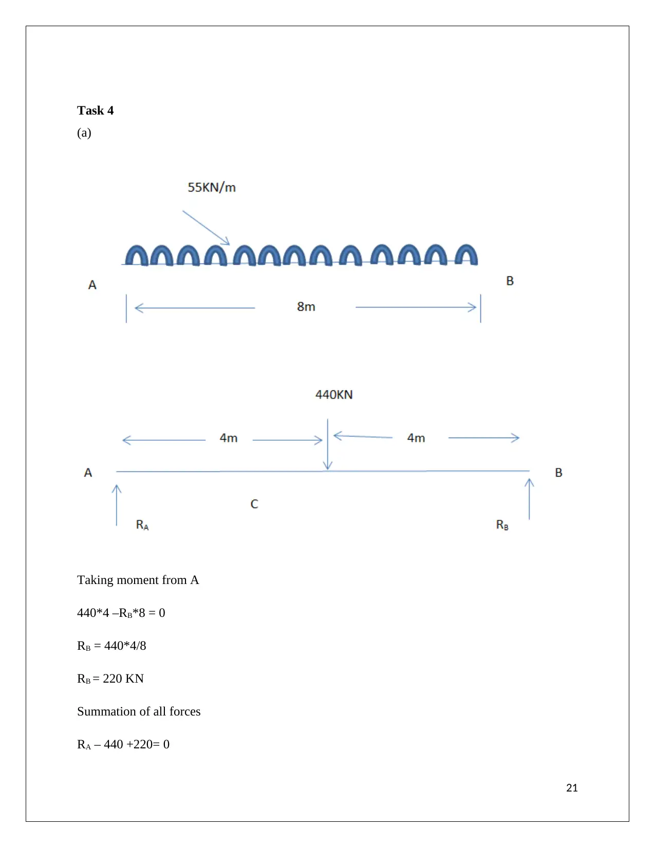
Task 4
(a)
Taking moment from A
440*4 –RB*8 = 0
RB = 440*4/8
RB = 220 KN
Summation of all forces
RA – 440 +220= 0
21
(a)
Taking moment from A
440*4 –RB*8 = 0
RB = 440*4/8
RB = 220 KN
Summation of all forces
RA – 440 +220= 0
21
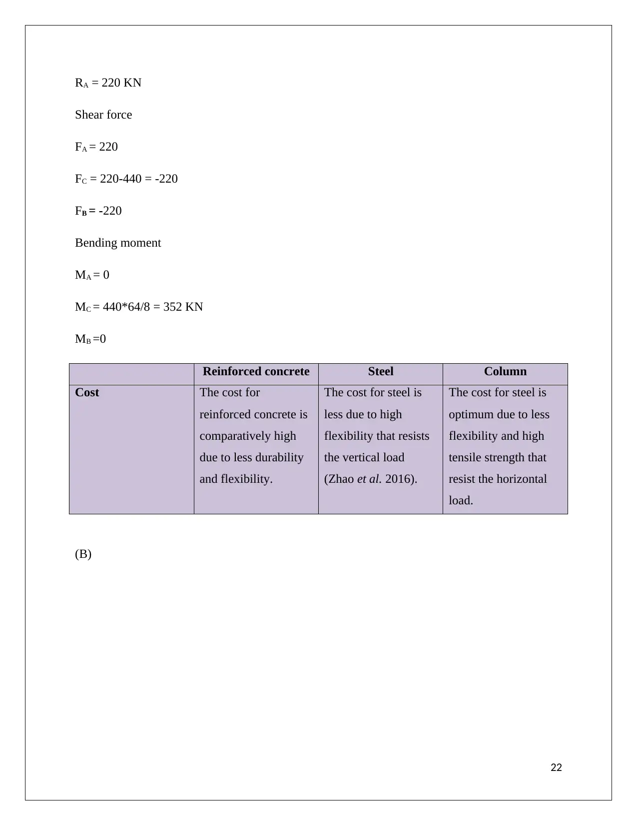
RA = 220 KN
Shear force
FA = 220
FC = 220-440 = -220
FB = -220
Bending moment
MA = 0
MC = 440*64/8 = 352 KN
MB =0
Reinforced concrete Steel Column
Cost The cost for
reinforced concrete is
comparatively high
due to less durability
and flexibility.
The cost for steel is
less due to high
flexibility that resists
the vertical load
(Zhao et al. 2016).
The cost for steel is
optimum due to less
flexibility and high
tensile strength that
resist the horizontal
load.
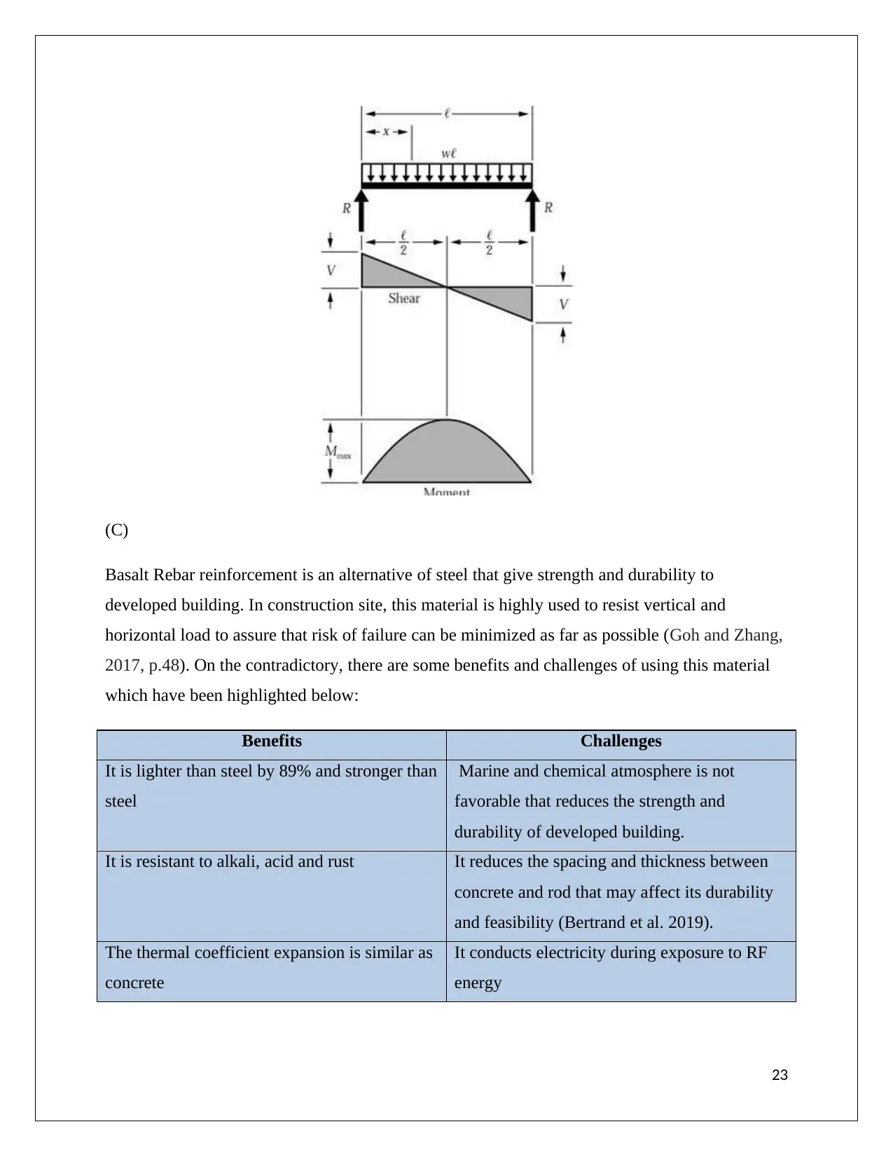
(B)
22
Secure Best Marks with AI Grader
Need help grading? Try our AI Grader for instant feedback on your assignments.
(C)
Basalt Rebar reinforcement is an alternative of steel that give strength and durability to
developed building. In construction site, this material is highly used to resist vertical and
horizontal load to assure that risk of failure can be minimized as far as possible (Goh and Zhang,
2017, p.48). On the contradictory, there are some benefits and challenges of using this material
which have been highlighted below:
Benefits Challenges
It is lighter than steel by 89% and stronger than
steel
Marine and chemical atmosphere is not
favorable that reduces the strength and
durability of developed building.
It is resistant to alkali, acid and rust It reduces the spacing and thickness between
concrete and rod that may affect its durability
and feasibility (Bertrand et al. 2019).
The thermal coefficient expansion is similar as
concrete
It conducts electricity during exposure to RF
energy
23
(D)
Building Information Modeling (BIM) is one of the essential and important aspects of
construction that help in developed an effective building (Fournier et al. 2019, p.4). It is used
for several purposes in production accurate structural design information, which have been listed
below:
Better Communication and Collaboration
Model based cost estimate
Safety of construction site get increased
Reduce risk of failure through clash detection
Potential risk can be mitigated easily
Increase prefabrication and productivity
24
Reference list
Aboutcivil.org (2019), Bending Moment, Available at: https://www.aboutcivil.org/simply-
supported-UDL-beam-formulas-bending-moment-equations.html [Accessed on 22 July 2019]
Bertrand, D., Tardif, N., Bourrier, F., Barré, J.B. and Grange, S., 2019. A novel identification
method for obtaining bending moment–curvature relations of wood stems based on digital image
correlation and SDOF analysis. European Journal of Environmental and Civil Engineering,
pp.1-14.
Cao, Y., Wu, Y.F. and Jiang, C., 2018. Stress-strain relationship of FRP confined concrete
columns under combined axial load and bending moment. Composites Part B: Engineering, 134,
pp.207-217.
Connect.bim360.autodesk.com (2019), Benefits of construction, Available at:
https://connect.bim360.autodesk.com/benefits-of-bim-in-construction [Accessed on 22 July
2019]
Fournier, E., Grihon, S., Bes, C. and Klein, T., 2019. Prediction of Preliminary Maximum Wing
Bending Moments under Discrete Gust. Journal of Aircraft, pp.1-4.
Goh, S.H. and Zhang, L., 2017. Estimation of peak acceleration and bending moment for pile-
raft systems embedded in soft clay subjected to far-field seismic excitation. Journal of
Geotechnical and Geoenvironmental Engineering, 143(11), p.04017082.
Lotfi, M., Farid, A.A. and Soleimanimehr, H., 2015. The effect of chip breaker geometry on chip
shape, bending moment, and cutting force: FE analysis and experimental study. The
International Journal of Advanced Manufacturing Technology, 78(5-8), pp.917-925.
Ocw.nthu.edu.tw (2019), Bending Moment, Available at:
http://ocw.nthu.edu.tw/ocw/upload/8/253/Chapter_4-98.pdf [Accessed on 22 July 2019]
Skyciv.com (2019), Structural analysis, Available at: https://skyciv.com/education/types-of-
supports-in-structural-analysis/ [Accessed on 22 July 2019]
25
Paraphrase This Document
Need a fresh take? Get an instant paraphrase of this document with our AI Paraphraser

Zhao, O., Gardner, L. and Young, B., 2016. Buckling of ferritic stainless steel members under
combined axial compression and bending. Journal of Constructional Steel Research, 117, pp.35-
48.
26
combined axial compression and bending. Journal of Constructional Steel Research, 117, pp.35-
48.
26
1 out of 26
Related Documents
Your All-in-One AI-Powered Toolkit for Academic Success.
+13062052269
info@desklib.com
Available 24*7 on WhatsApp / Email
![[object Object]](/_next/static/media/star-bottom.7253800d.svg)
Unlock your academic potential
© 2024 | Zucol Services PVT LTD | All rights reserved.


