Data Representation and Digital Logic: Boolean Algebra Assignment

Verified

Added on  2019/11/19

|5
|437
|541
Homework Assignment
AI Summary
This assignment solution covers Boolean algebra, focusing on data representation and digital logic concepts. It includes the conversion of a decimal number to single-precision IEEE 754 format, and the representation of a 5-bit word using signed magnitude, one's complement, and two's complement methods. The assignment further delves into representing the hours of a clock in a 5-bit binary format, creating a timing diagram for a 12-hour clock period, and designing a logic circuit using basic logic gates (AND, OR, NOT) to control a door based on the clock time. The solution also includes the proof of a Boolean algebra expression using algebraic manipulation.
Document Page
Running head: BOOLEAN ALGEBRA
Boolean algebra
Name of the student
Name of the University
Student Id
Subject code (ITC544)
Assignment 1: Data representation and digital logic
Author note
tabler-icon-diamond-filled.svg

Paraphrase This Document

Need a fresh take? Get an instant paraphrase of this document with our AI Paraphraser
Document Page
Page 1 of 5BOOLEAN ALGEBRA
Answer 1:
a)
Single precision IEEE 754 format- 0 01111110 10100000000000000000000
The first MSB is the sign, the middle portion is the exponent and the last portion is the
mantissa.
Decimal conversion- 8.125 * 10^-1
b)
5-bit word- 0 1010
Signed magnitude- +10 (Most significant bit-0 [positive] rest 4 bits are magnitude)
One’s complement- 10101 (all the 0’s are replaced by 1 and vice-versa)
Two’s complement- 10110 (1 is added to the one’s complement)
Answer 2:
a)
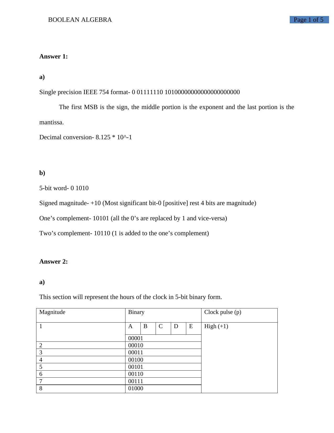
This section will represent the hours of the clock in 5-bit binary form.
Magnitude Binary Clock pulse (p)
1 A B C D E High (+1)
00001
2 00010
3 00011
4 00100
5 00101
6 00110
7 00111
8 01000
Document Page
Page 2 of 5BOOLEAN ALGEBRA
9 01001
10 01010
11 01011
12 01100
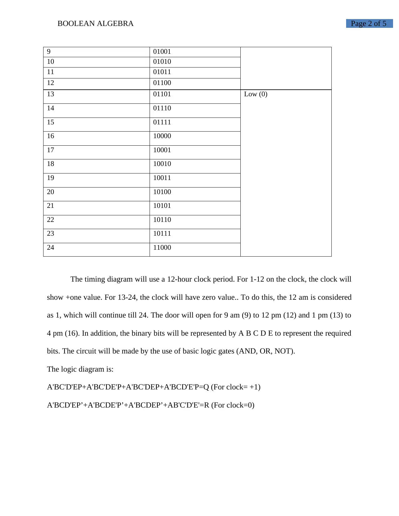
13 01101 Low (0)
14 01110
15 01111
16 10000
17 10001
18 10010
19 10011
20 10100
21 10101
22 10110
23 10111
24 11000
The timing diagram will use a 12-hour clock period. For 1-12 on the clock, the clock will
show +one value. For 13-24, the clock will have zero value.. To do this, the 12 am is considered
as 1, which will continue till 24. The door will open for 9 am (9) to 12 pm (12) and 1 pm (13) to
4 pm (16). In addition, the binary bits will be represented by A B C D E to represent the required
bits. The circuit will be made by the use of basic logic gates (AND, OR, NOT).
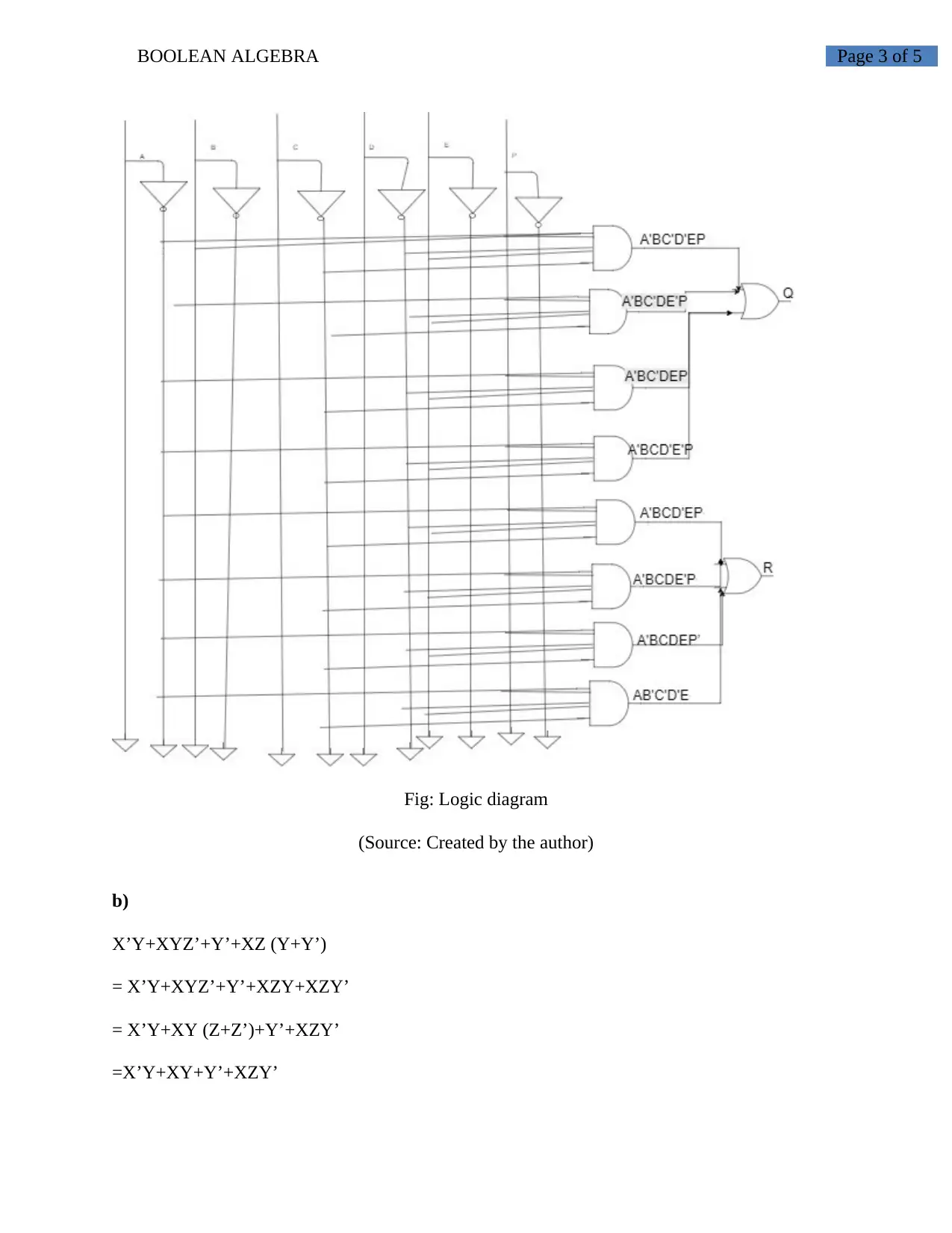
The logic diagram is:
A'BC'D'EP+A'BC'DE'P+A'BC'DEP+A'BCD'E'P=Q (For clock= +1)
A'BCD'EP’+A'BCDE'P’+A'BCDEP’+AB'C'D'E'=R (For clock=0)
Document Page
Page 3 of 5BOOLEAN ALGEBRA
Fig: Logic diagram
(Source: Created by the author)
b)
X’Y+XYZ’+Y’+XZ (Y+Y’)
= X’Y+XYZ’+Y’+XZY+XZY’
= X’Y+XY (Z+Z’)+Y’+XZY’
=X’Y+XY+Y’+XZY’
tabler-icon-diamond-filled.svg

Paraphrase This Document

Need a fresh take? Get an instant paraphrase of this document with our AI Paraphraser
Document Page
Page 4 of 5BOOLEAN ALGEBRA
=Y+Y’+XZY’
=1+XZY’
=1 (PROVED)
chevron_up_icon
1 out of 5
circle_padding
hide_on_mobile
zoom_out_icon
[object Object]