Electronics 16 Assignment Solution - PLC Module - University Name
VerifiedAdded on 2022/08/11
|18
|2614
|451
Homework Assignment
AI Summary
This document presents a comprehensive solution to an electronics assignment, covering various aspects of digital logic and programmable logic controllers (PLCs). The assignment includes problems on Boolean expressions, truth tables, and logic circuit design using NAND gates. It also involves hexadecimal and binary number conversions, including 2's complement and BCD representations. Furthermore, the solution addresses the disadvantages of relays compared to PLCs and explores PLC input and output interfaces, including optocoupler and relay output module circuit analysis with calculations of current and voltage drops. The assignment demonstrates a solid understanding of digital electronics, circuit analysis, and PLC fundamentals.

Running head: ELECTRONICS
ELECTRONICS
Name of the Student:
Name of the University:
Author’s Note:
ELECTRONICS
Name of the Student:
Name of the University:
Author’s Note:
Paraphrase This Document
Need a fresh take? Get an instant paraphrase of this document with our AI Paraphraser
1ELECTRONICS
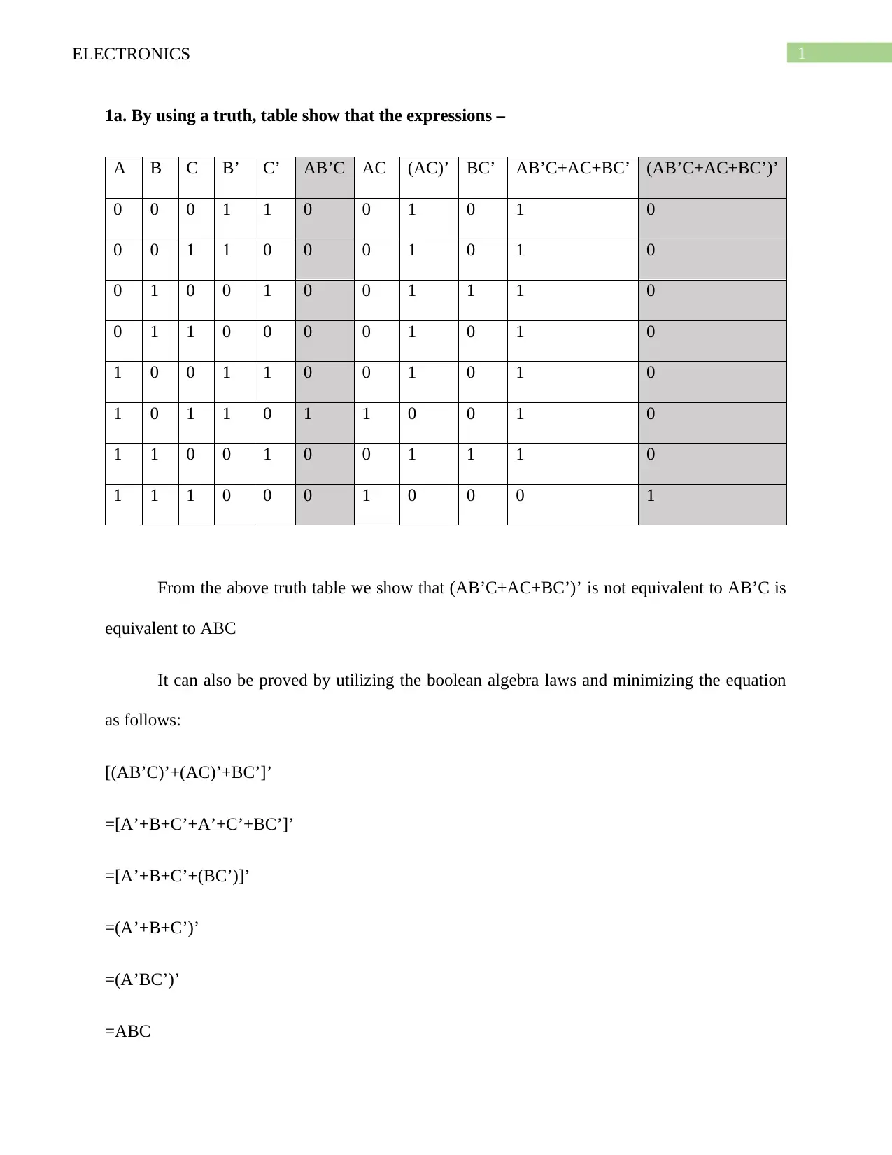
1a. By using a truth, table show that the expressions –
A B C B’ C’ AB’C AC (AC)’ BC’ AB’C+AC+BC’ (AB’C+AC+BC’)’
0 0 0 1 1 0 0 1 0 1 0
0 0 1 1 0 0 0 1 0 1 0
0 1 0 0 1 0 0 1 1 1 0
0 1 1 0 0 0 0 1 0 1 0
1 0 0 1 1 0 0 1 0 1 0
1 0 1 1 0 1 1 0 0 1 0
1 1 0 0 1 0 0 1 1 1 0
1 1 1 0 0 0 1 0 0 0 1
From the above truth table we show that (AB’C+AC+BC’)’ is not equivalent to AB’C is
equivalent to ABC
It can also be proved by utilizing the boolean algebra laws and minimizing the equation
as follows:
[(AB’C)’+(AC)’+BC’]’
=[A’+B+C’+A’+C’+BC’]’
=[A’+B+C’+(BC’)]’
=(A’+B+C’)’
=(A’BC’)’
=ABC
2ELECTRONICS
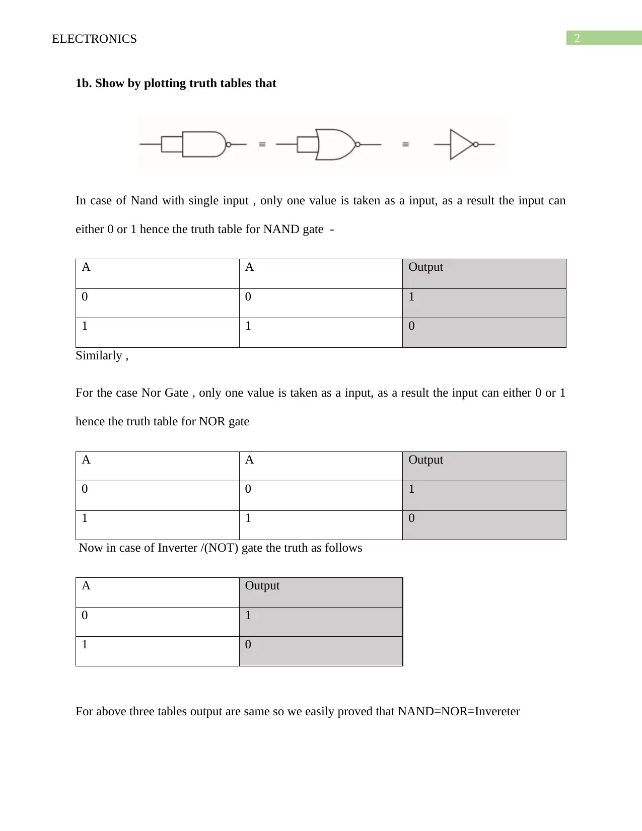
1b. Show by plotting truth tables that
In case of Nand with single input , only one value is taken as a input, as a result the input can
either 0 or 1 hence the truth table for NAND gate -
A A Output
0 0 1
1 1 0
Similarly ,
For the case Nor Gate , only one value is taken as a input, as a result the input can either 0 or 1
hence the truth table for NOR gate
A A Output
0 0 1
1 1 0
Now in case of Inverter /(NOT) gate the truth as follows
A Output
0 1
1 0
For above three tables output are same so we easily proved that NAND=NOR=Invereter
⊘ This is a preview!⊘
Do you want full access?
Subscribe today to unlock all pages.

Trusted by 1+ million students worldwide
3ELECTRONICS
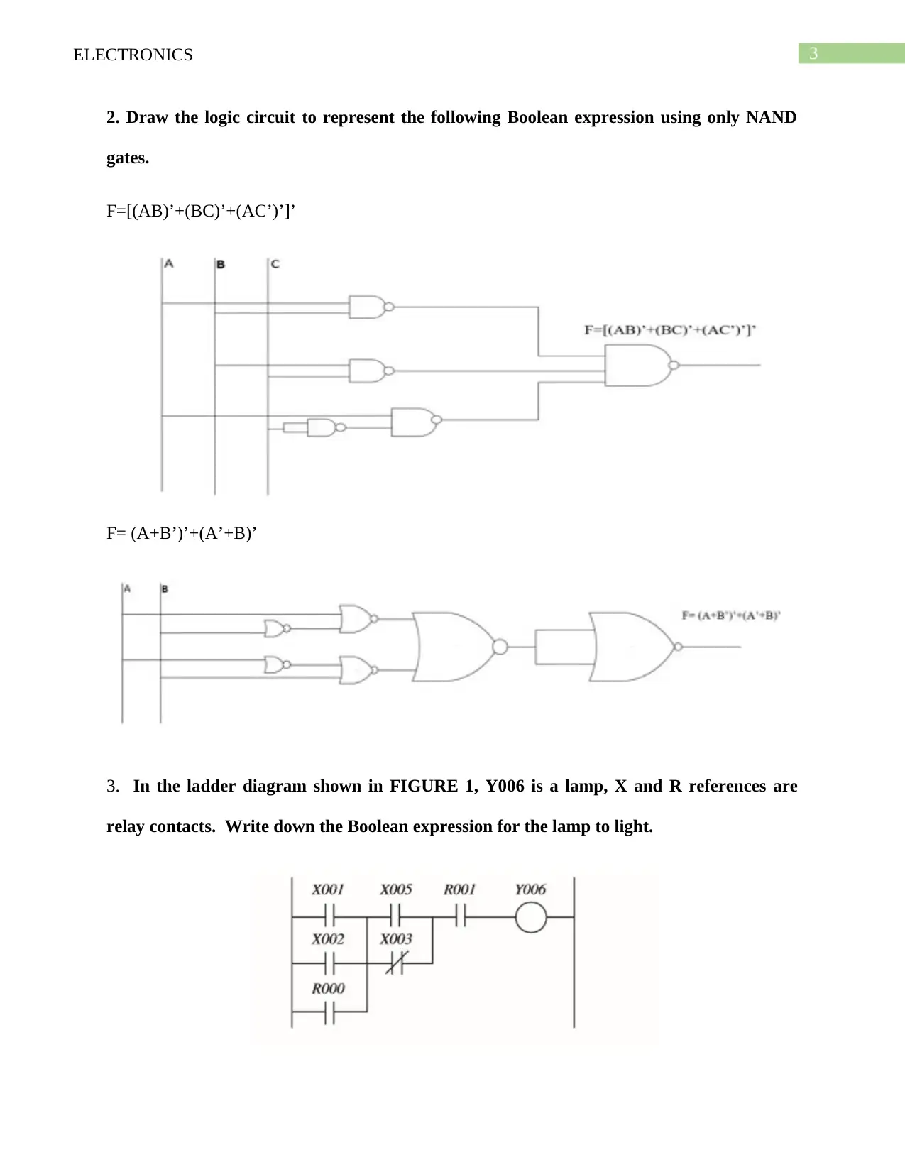
2. Draw the logic circuit to represent the following Boolean expression using only NAND
gates.
F=[(AB)’+(BC)’+(AC’)’]’
F= (A+B’)’+(A’+B)’
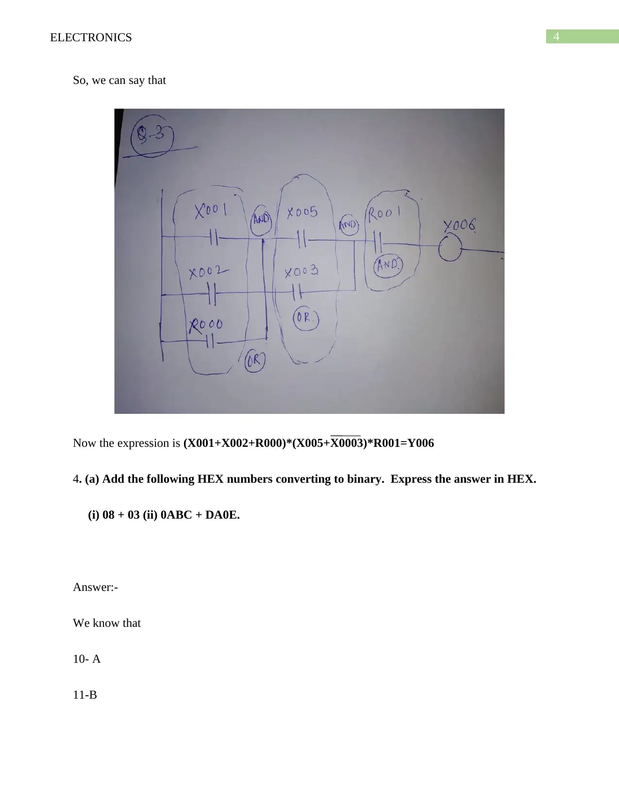
3. In the ladder diagram shown in FIGURE 1, Y006 is a lamp, X and R references are
relay contacts. Write down the Boolean expression for the lamp to light.
2. Draw the logic circuit to represent the following Boolean expression using only NAND
gates.
F=[(AB)’+(BC)’+(AC’)’]’
F= (A+B’)’+(A’+B)’
3. In the ladder diagram shown in FIGURE 1, Y006 is a lamp, X and R references are
relay contacts. Write down the Boolean expression for the lamp to light.
Paraphrase This Document
Need a fresh take? Get an instant paraphrase of this document with our AI Paraphraser
4ELECTRONICS
So, we can say that
Now the expression is (X001+X002+R000)*(X005+X0003)*R001=Y006
4. (a) Add the following HEX numbers converting to binary. Express the answer in HEX.
(i) 08 + 03 (ii) 0ABC + DA0E.
Answer:-
We know that
10- A
11-B
So, we can say that
Now the expression is (X001+X002+R000)*(X005+X0003)*R001=Y006
4. (a) Add the following HEX numbers converting to binary. Express the answer in HEX.
(i) 08 + 03 (ii) 0ABC + DA0E.
Answer:-
We know that
10- A
11-B
5ELECTRONICS
12-C
13-D
14-E
15-F
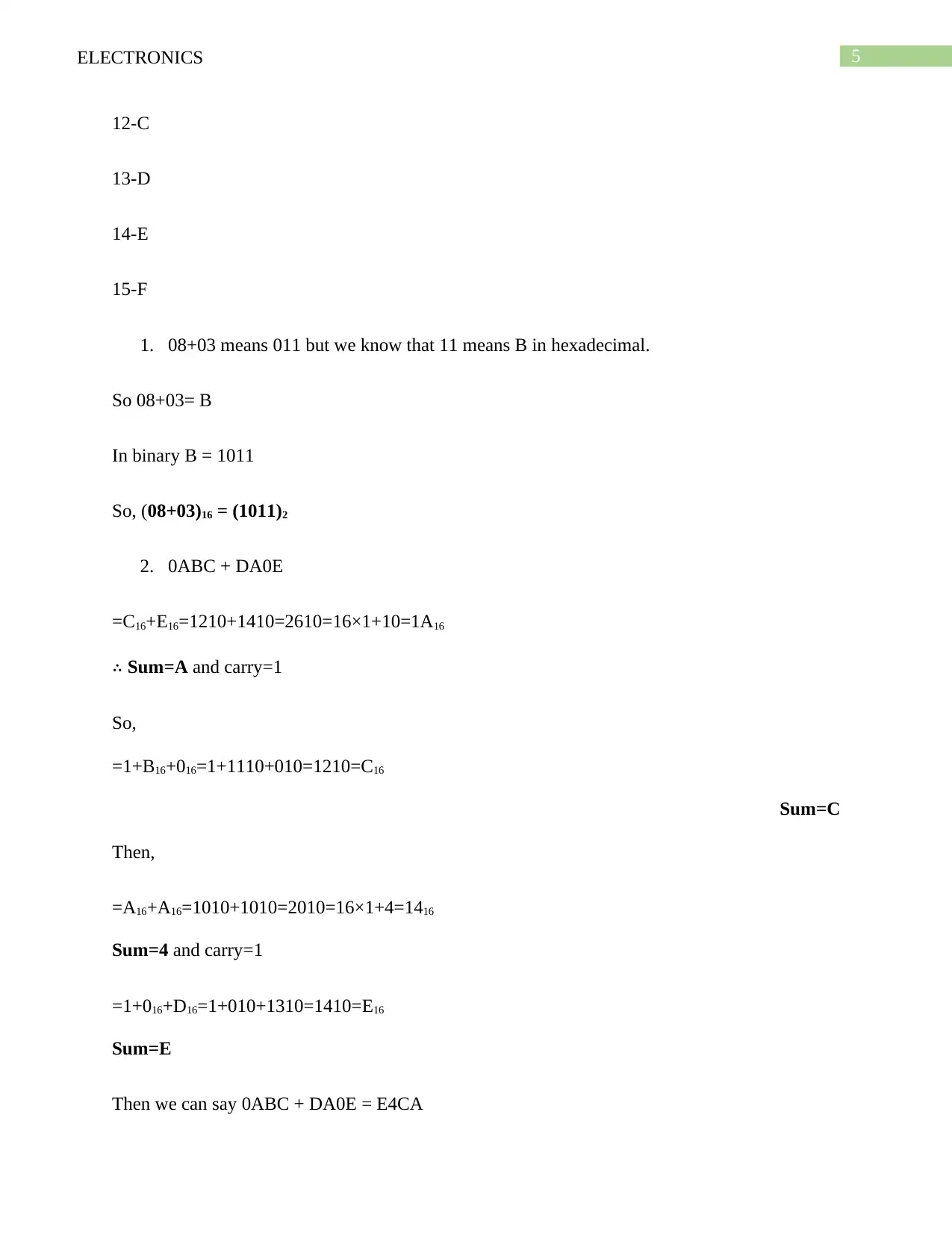
1. 08+03 means 011 but we know that 11 means B in hexadecimal.
So 08+03= B
In binary B = 1011
So, (08+03)16 = (1011)2
2. 0ABC + DA0E
=C16+E16=1210+1410=2610=16×1+10=1A16
∴ Sum=A and carry=1
So,
=1+B16+016=1+1110+010=1210=C16
Sum=C
Then,
=A16+A16=1010+1010=2010=16×1+4=1416
Sum=4 and carry=1
=1+016+D16=1+010+1310=1410=E16
Sum=E
Then we can say 0ABC + DA0E = E4CA
⊘ This is a preview!⊘
Do you want full access?
Subscribe today to unlock all pages.

Trusted by 1+ million students worldwide
6ELECTRONICS
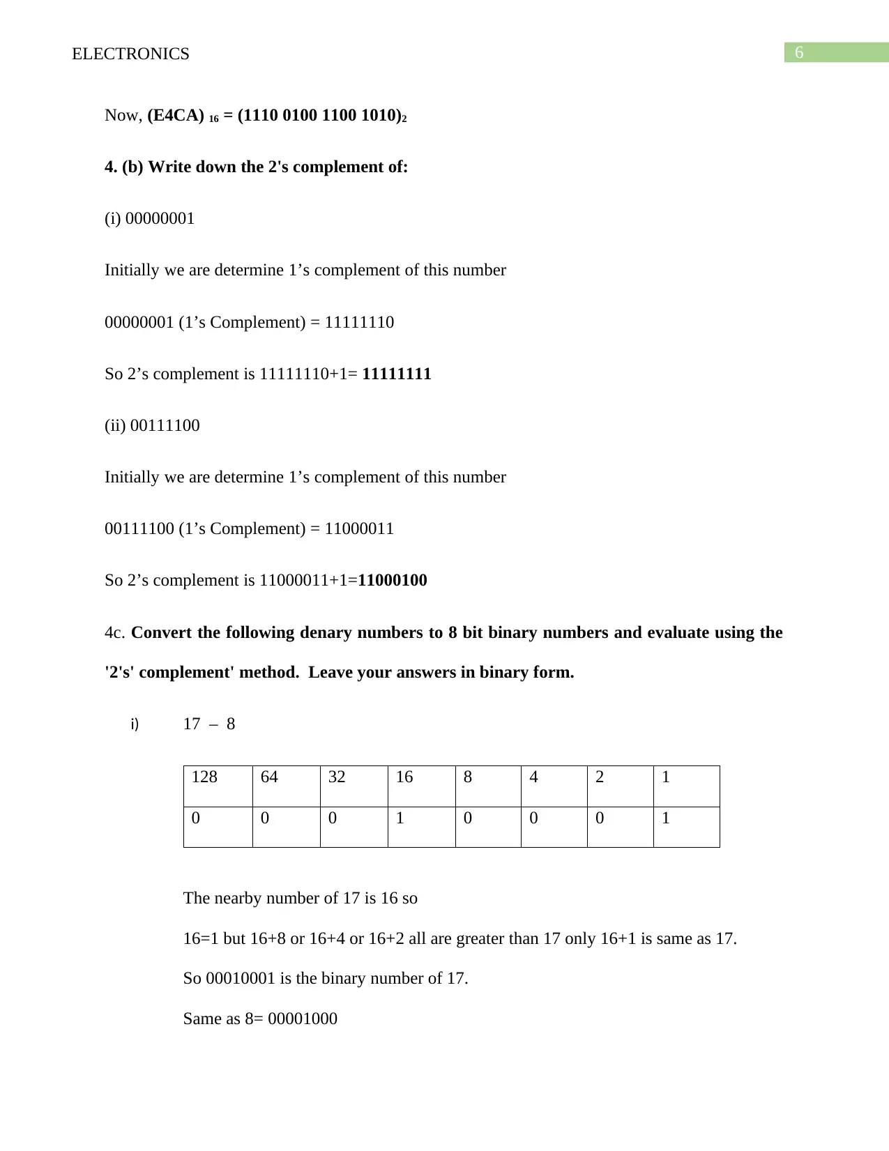
Now, (E4CA) 16 = (1110 0100 1100 1010)2
4. (b) Write down the 2's complement of:
(i) 00000001
Initially we are determine 1’s complement of this number
00000001 (1’s Complement) = 11111110
So 2’s complement is 11111110+1= 11111111
(ii) 00111100
Initially we are determine 1’s complement of this number
00111100 (1’s Complement) = 11000011
So 2’s complement is 11000011+1=11000100
4c. Convert the following denary numbers to 8 bit binary numbers and evaluate using the
'2's' complement' method. Leave your answers in binary form.
i) 17 – 8
128 64 32 16 8 4 2 1
0 0 0 1 0 0 0 1
The nearby number of 17 is 16 so
16=1 but 16+8 or 16+4 or 16+2 all are greater than 17 only 16+1 is same as 17.
So 00010001 is the binary number of 17.
Same as 8= 00001000
Paraphrase This Document
Need a fresh take? Get an instant paraphrase of this document with our AI Paraphraser
7ELECTRONICS
128 64 32 16 8 4 2 1
0 0 0 0 1 0 0 0
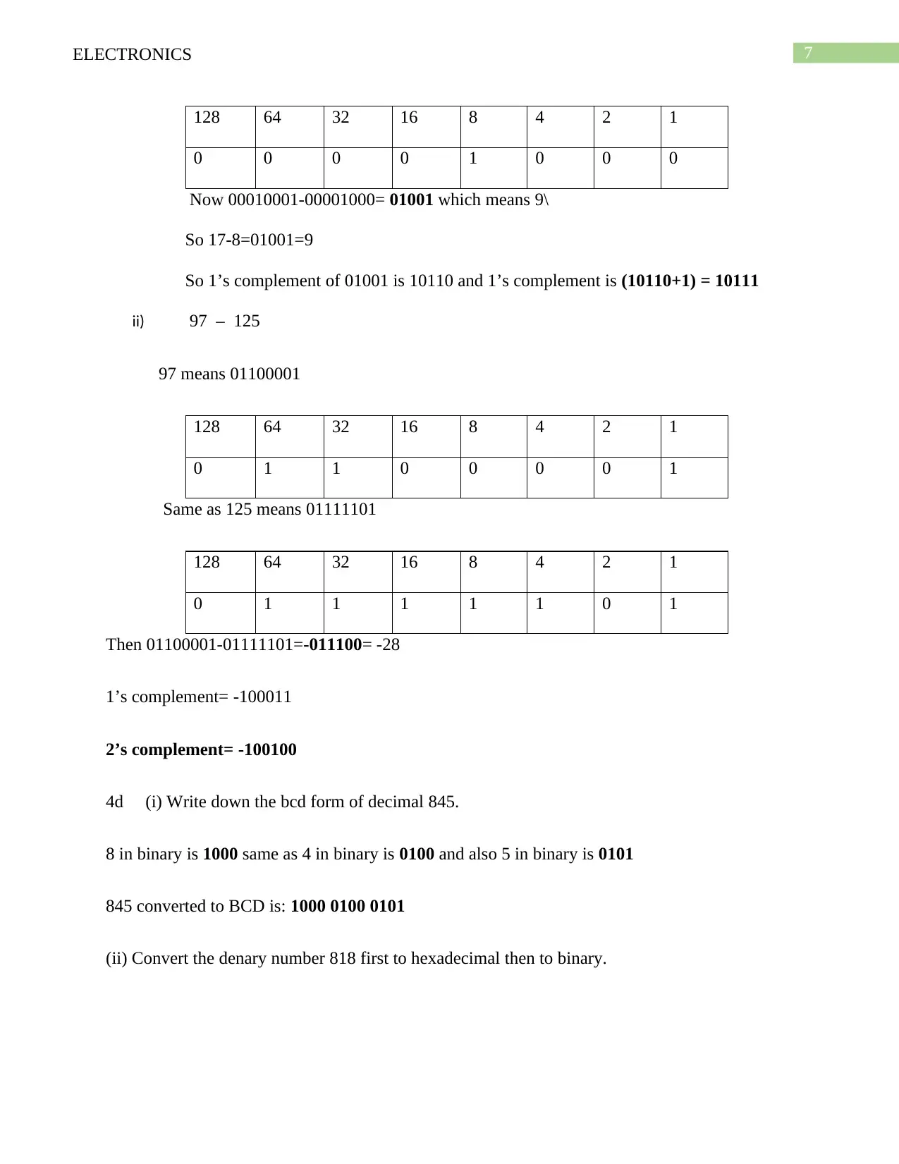
Now 00010001-00001000= 01001 which means 9\
So 17-8=01001=9
So 1’s complement of 01001 is 10110 and 1’s complement is (10110+1) = 10111
ii) 97 – 125
97 means 01100001
128 64 32 16 8 4 2 1
0 1 1 0 0 0 0 1
Same as 125 means 01111101
128 64 32 16 8 4 2 1
0 1 1 1 1 1 0 1
Then 01100001-01111101=-011100= -28
1’s complement= -100011
2’s complement= -100100
4d (i) Write down the bcd form of decimal 845.
8 in binary is 1000 same as 4 in binary is 0100 and also 5 in binary is 0101
845 converted to BCD is: 1000 0100 0101
(ii) Convert the denary number 818 first to hexadecimal then to binary.
128 64 32 16 8 4 2 1
0 0 0 0 1 0 0 0
Now 00010001-00001000= 01001 which means 9\
So 17-8=01001=9
So 1’s complement of 01001 is 10110 and 1’s complement is (10110+1) = 10111
ii) 97 – 125
97 means 01100001
128 64 32 16 8 4 2 1
0 1 1 0 0 0 0 1
Same as 125 means 01111101
128 64 32 16 8 4 2 1
0 1 1 1 1 1 0 1
Then 01100001-01111101=-011100= -28
1’s complement= -100011
2’s complement= -100100
4d (i) Write down the bcd form of decimal 845.
8 in binary is 1000 same as 4 in binary is 0100 and also 5 in binary is 0101
845 converted to BCD is: 1000 0100 0101
(ii) Convert the denary number 818 first to hexadecimal then to binary.
8ELECTRONICS
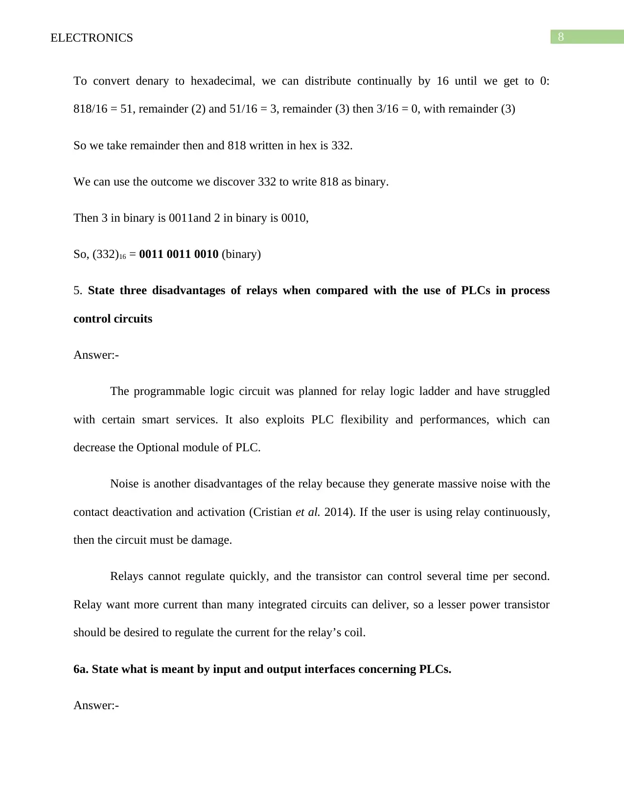
To convert denary to hexadecimal, we can distribute continually by 16 until we get to 0:
818/16 = 51, remainder (2) and 51/16 = 3, remainder (3) then 3/16 = 0, with remainder (3)
So we take remainder then and 818 written in hex is 332.
We can use the outcome we discover 332 to write 818 as binary.
Then 3 in binary is 0011and 2 in binary is 0010,
So, (332)16 = 0011 0011 0010 (binary)
5. State three disadvantages of relays when compared with the use of PLCs in process
control circuits
Answer:-
The programmable logic circuit was planned for relay logic ladder and have struggled
with certain smart services. It also exploits PLC flexibility and performances, which can
decrease the Optional module of PLC.
Noise is another disadvantages of the relay because they generate massive noise with the
contact deactivation and activation (Cristian et al. 2014). If the user is using relay continuously,
then the circuit must be damage.
Relays cannot regulate quickly, and the transistor can control several time per second.
Relay want more current than many integrated circuits can deliver, so a lesser power transistor
should be desired to regulate the current for the relay’s coil.
6a. State what is meant by input and output interfaces concerning PLCs.
Answer:-
⊘ This is a preview!⊘
Do you want full access?
Subscribe today to unlock all pages.

Trusted by 1+ million students worldwide
9ELECTRONICS
PLC has become a vital part of the manufacturing environment. As a technical expert
involved with the procedures regulated by PLCs, it is essential to recognize their fundamental
capabilities and functionalities (Swathika et al. 2016). A PLC is a model of a real-time structure;
subsequently, output results should be formed in response to input situations within a restricted
time, else the unintended process will result. Input modules of PLC deliver the electrical
connection between the internal process and field device. They fluctuate in types and voltages of
signals formed such as on, offer an adaptable energy.
More definitely, a PLC would be used for the computerization of industrialized
electromechanical procedures, such as regulator of equipment on factory assembly positions,
amusement outings, or food processing (Martinov, Kozak and Nezhmetdinov 2017). They are
considered for several preparations of analogue and digital outputs and inputs with prolonged
temperature ratio, insusceptibility to electrical noise, and resistance to impact and vibration. A
PLC will contain some significant sections like CPU and I/O interface.
The I/O system is actually connected to main device and delivers the interface between
the controllable device and CPU. Subsequently, the CPU develops the input records it will then
create any desirable output variations after implementing the user program (Süß, et al. 2016).
There are some s primary stages in the process of all PLCs like Program Scan, Input Scan,
Housekeeping and Output Scan. These stages repetitively take place in a recapping loop.
The usual logic circuit has an extensive range of Input/output modules available to
accommodate every type of output devices and sensors. For instance, discrete input elements can
be used to identify object existence or events with tools like as photoelectric sensors or
proximity, pushbuttons and switches. Separate output units can regulate “ON/OFF” loads like
lights, motors and solenoid valves. The analogue system can receive signals from process
Paraphrase This Document
Need a fresh take? Get an instant paraphrase of this document with our AI Paraphraser
10ELECTRONICS
composition like as flow, pressure, level transmitters and temperature. The output signal
command loads that require a fluctuating control signal, like analogue flow valves or panel
meters. Many PLCs also deal with particular modules like as motion control or Input/Output, and
Ethernet or serial communications.
6b. State briefly what the function of interfaces is concerning the different types of process
signal.
Answer:-
The I/O interface links the processor to the external world and is consequently an
essential part of the processing system. When the processing unit puts the locations of a marginal
onto the address bus, the I/O interface interprets the area. It recognizes the exclusive computer
bordering with which an information transfer process is to be implemented (Kondratenko,
Korobko and Kozlov 2017). The significant functions or requirement implemented into some
categories like regulation timing, bus arbitrations, data transformations, CPU communication etc.
The Input-Output module receives commands from the mainframe, usually sent as
indications on the control bus. Therefore, an I/O module must identify one exclusive location for
every peripheral it regulates. The output and input sections are where the computer accepts data
from outward devices and connects the evidence to external devices (Han et al. 2014). The
communications interface is applied to transmit and receive documents on communication
networks from the logic circuit. It is disturbed with such arrangements as synchronization, data
acquisition, device verification between connection management and user applications.
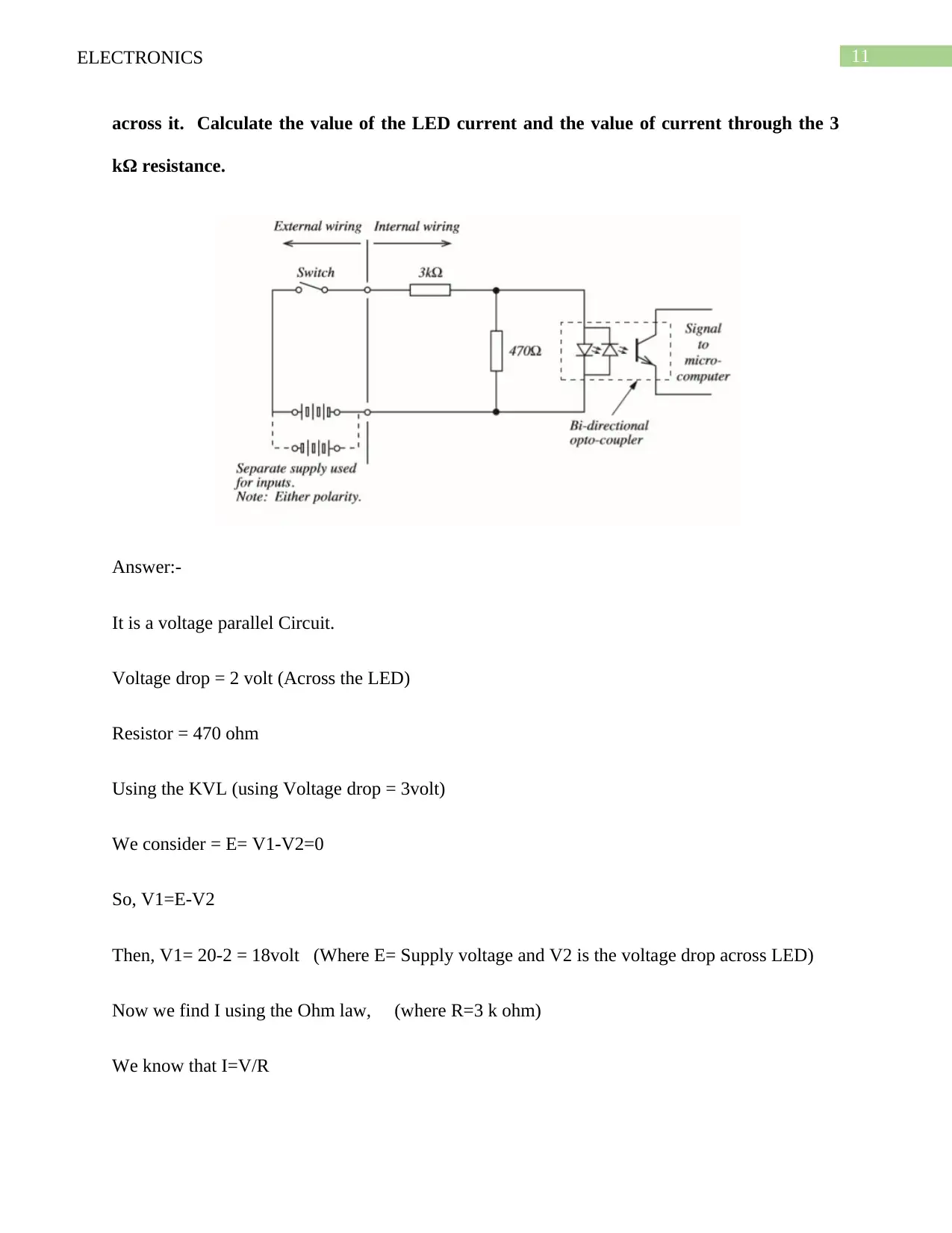
6c. The diagram of FIGURE 2 shows a bi-directional optocoupler input interface circuit.
When a supply voltage of 20 V is applied, the LED carries a current and 2 V is dropped
11ELECTRONICS
across it. Calculate the value of the LED current and the value of current through the 3
kΩ resistance.
Answer:-
It is a voltage parallel Circuit.
Voltage drop = 2 volt (Across the LED)
Resistor = 470 ohm
Using the KVL (using Voltage drop = 3volt)
We consider = E= V1-V2=0
So, V1=E-V2
Then, V1= 20-2 = 18volt (Where E= Supply voltage and V2 is the voltage drop across LED)
Now we find I using the Ohm law, (where R=3 k ohm)
We know that I=V/R
⊘ This is a preview!⊘
Do you want full access?
Subscribe today to unlock all pages.

Trusted by 1+ million students worldwide
1 out of 18
Related Documents
Your All-in-One AI-Powered Toolkit for Academic Success.
+13062052269
info@desklib.com
Available 24*7 on WhatsApp / Email
![[object Object]](/_next/static/media/star-bottom.7253800d.svg)
Unlock your academic potential
Copyright © 2020–2025 A2Z Services. All Rights Reserved. Developed and managed by ZUCOL.


