Detailed Literature Review and Analysis of Automotive Braking Systems
VerifiedAdded on 2024/05/30

1
Paraphrase This Document

Literature Review.......................................................................................................................3
Methodology............................................................................................................................20
Analysis....................................................................................................................................35
Conclusion................................................................................................................................45
2
In the literature review part, there’s the discussion of the different type of Braking System.
The development of the braking system for the different automobiles is analysed in the
literature review part. The braking system used to be different for the different purposes.
According to the necessity the development of the braking system used to be accomplished.
There is the development of the different type of automobiles as the time goes on. According
to that Braking System used to develop. The development of the braking system also depends
on the wheel of the particular automobile. If the particular automobile is having the wheel of
iron then in the starting phase wooden block Braking gets developed. There is the
development of Braking System on the basis of rubber tyre also. The Braking System for the
train also gets developed. In this way, it can be said that the braking system also depends on
the type of the particular automobile. As the time passes the development in the technology
and the innovation in the braking system also attained. Different manufacturers, engineers
and designers proposed the different type of Braking System. In such type of Braking
System, the development used to take place according to the time.
A brake is a mechanical device that can inhibit the motion of the moving object or the
system. The brake is particularly used in the vehicle, axle or the wheel to slow down that
particular object. The method that is used in the stopping of the vehicle, axle and the wheel is
done with the help of the friction.
The kinetic energy of the particular object that is moving is converting into the heat. The
friction between the two surfaces is generated and the conversion gets accomplished. In this
way, the braking system gets accomplished (Byun, 2017). Rotating axle of the wheel are the
areas at which brakes are applied. The variation in the application on the brake can be seen
like the surface of the fluid is the target for which brakes can be applied.
In the 18th century, it was tested to slow the momentum of the wheel or the vehicle was
accomplished. It is very hard to decide the inventor of the braking system due to the presence
of the different form of the brakes (Zhao, et. al., 2013). The innovation in the braking system
is the output due to the regular development of the braking system.
The proper control of the human on the motor vehicle was the goal that was decided at the
time of developing and testing the braking system (Saravanan, 2015). The evolution of the
3
⊘ This is a preview!⊘
Do you want full access?
Subscribe today to unlock all pages.

Trusted by 1+ million students worldwide
were developed. Then after the braking system gets developed as the time passes.
Wooden Block Brakes
The wooden blocks that are present in this braking system are responsible for the
brake implementation for the stopping the vehicle. In such type of brakes only there is
one lever present that is responsible for stopping the motion of the wheel of the
vehicle.
This method was very successful in the steel-rimmed wheels. This method was
used in horse-drawn. The normal speed that can be stopped with the help of such type
of brake is 10-20 mph.
In the late 1890 Michelin brothers introduced rubber tires such type of brake lose
its market position (Keppy, 2018). This type of brake was not useful in the rubber
tires that’s why lose its market position and at the same time rubber tires gain the
popular in the market.
Drum Brakes
Mechanical drum brakes were the brakes that are known as the foundation of the
braking system that is used in the modern times. This braking system was developed
in 1902 by Louis Renault. This person belongs to France. Cable wrapped drum
anchored brake was used in such type of the braking system that helped in the
development of the braking system further (Keppy, 2018). Gottlieb Daimler created
the concept of drum brakes.
After that Louis Renault developed the drum brakes that became standard for the
car braking system. The drum brake is also called as internal expanding shoe system
and has the shape of cylindrical drum type.
The main advantages of such type of the brake were production and the purchase
cost of such type of brakes was easier. This type of brakes can also be used with the
disc brakes (Keppy, 2018). The main limitations in such type of brakes were it
produces excessive heating that may cause heavy braking and this can cause
distortion.
4
Paraphrase This Document
may increase. Excessive heating can also cause brake fluid to vaporize is another
drawback that was considered.
Maintenance is quite complex as it takes much time. After that the in the year of
1950, there are using the drum brakes wears, brakes mandatory physical change until
the outline of self- regulating drum brakes.
In the year of 1953, the Jaguar fielded cars that are armed with the disc brakes at
the Le Mans, in that the larger share due to their larger braking over the drum-arm
rivals. In the United States, the Jeep CJ-5 was the final automobile to; get obverse
drum brakes when it was phased out in 1984.
Internal shoe brakes
After that, there was the development of the internal shoe brake. After the
invention of this type of the brake, all braking system is installed outside the vehicles.
This type of brake is having two type of shoe (Monopoli & Giordano, 2012). The
outer surface of the shoes is having the frictional material. This is accomplished so
that there will not be any wearing that used to occur at the time of the application of
the brake.
The shoes are pivoted at the one end that makes is having the contact on the other
end of the cam. In this way, the structuring of such type of braking system is done. At
the time of the application of brake, the torque is produced that results in the slowing
of the speed of the drum.
The spring is present in this braking system which is held off to the position of the
shoe. This enclose of this braking system is the drum. This is the type of enclosure
that used to protect the mechanism from the dust, moisture and water (Kümmel, et.
al., 2018). This is the type of the brake that is used in the cars and the trucks.
The left-hand side shoe is known as the primary shoe in which the drum used to
rotate in the anti-clockwise direction. The right-hand shoe of this brake is known as
the secondary shoe. This is the type of shoe that is also called as trailing shoe while
the primary shoe of this type of brake is known as leading shoe.
5
type of a break. Another advantage of this type of brake is simple construction. There
is a small number of parts present in such type of brakes (Röhling, 2016).
The small actuating force in such type of brake can produce large braking torques
that help in the slowing the speed of the vehicle instantly.
The dust particle and the moisture are unable to enter in such type of brake.
Talking on the terms of the reliability of this type of brake such it is quite fair that is
helping in the increasing of the ability of such type of break in the market.
It is the type of braking system that can be available at the reasonable cost.
The heat dissipating capacity of this type of brake is very less. This is resulting in
the heating of the braking system (Röhling, 2016). This is the big disadvantage of this
type of braking that can’t be ignored at any cost.
Hydraulic brake system
With the application of the hydraulics, the brake can be applied. This is the
braking system that used to works on the four wheel brake system. This type of
braking system was developed in 1918. Malcolm Loughead provides the concept of
this type of brake.
The force is transfer in the shoe of the break with the help of the Lockheed. In this
process, the use of cylinder and tubes are also used (Röhling, 2016). This process is
done when the driver presses the pedal of the brake.
This is the type of braking system that used to require very less effort for the
application of the brakes. In 1921 this braking system that was first fitted in the
Duesenberg car.
In the starting phase of application of this type of brake in the cars, there was the
problem of the leakage of the fluid. This problem was solved by the Maxwell Motor
Corporation. This company used to produce the rubber cup seals for such brakes (Lv,
et. al., 2014). This helps in eradication of the problem of the leakage.
6
⊘ This is a preview!⊘
Do you want full access?
Subscribe today to unlock all pages.

Trusted by 1+ million students worldwide
was the main user of this type of brake that used this braking system. This car used to
provide the facility of upgrading the braking system at $75 more than the total cost of
the car. Chrysler cars are the type of the brake that used this type of brake from 1924
to 1962.
After this many other cars were equipped with this type of the brake. Dodge,
Plymouth REO, Franklin Graham DeSoto, and Chrysler’s were many of the car
manufacturing companies that used this type of braking system for their cars (Wang,
et. al., 2013).
Ford and the General motors were the main player in the automobile sector that
doesn’t use this type of brake. They were stuck on mechanical brakes. The General
motor used four-wheel mechanical brakes from the mid 30’s in the twenty century. In
1938 ford and the general motors both started to use the hydraulic braking system.
The hydraulic braking system works over the Pascal law and refers to the drum
brakes, then this arrangement contains the hydraulic trundle cylinders, brakes shoes,
brake drum and the brake shoes.
At the time when the brake lever is practical the two bent brake shoes that have
the friction substantial lining are involuntary by the hydraulic helm cylinders in
contradiction of the internal surface of the revolving brake drum.
There are different types of advantages that can be seen for the hydraulic brakes.
There are 4 different cylinders present in such type of brakes. In all cylinders, the total
braking effort is equal (Midgley, et. al., 2013). There is no load of braking on the
particular one cylinder. This is the advantage of this type of Braking System which is
not present in another type of brakes that are discussed above.
There are very fewer chances of wear of the brake. The reason behind this is
because of the load on all 4 cylinders at the time of braking.
The system construction of this type of brake is also very simple. There is the
presence of less number of mechanical linkages as compared to the conventional type
of brake System.
7
Paraphrase This Document
return obtaining the high output force can be the result. This helps to repair of such
type of brakes. Therefore it can be said that there is a mechanical advantage in such
type of brake.
There can be different disadvantages and the limitation of this Braking System
also. They can be the situation in which can leakage can be possible in this type of
Braking System (Park & Choi, 2013). The liquids used to be slight but it can cause a
great effect on the Braking System.
The hydraulic brakes can be suitable for the application of intermittent brake
which is a disadvantage for such type of Braking System.
The actuation speed in such type of brake is slow as compared to the pneumatic
brake. Because of such type of limitations, there is the need that arrived at the past
time to use a different type of brakes that can overcome the different limitation
(Ezawa, K., & Raksincharoensak, 2014).
Fluids used in this brake are messy; Fluids might leak from hot areas and cause
spark out. Serious injuries may cause due to their burst. Highly corrosive in nature.
Regular change of filters and seals are required.
Disc Brake
The disc brake was invented in the year 1898. The other above discussed Brake
was used before that disc brake in the car and other automobiles. This Brake gained
popularity after many years of invention.
Elmer Ambrose Sperry was the automobile designer that used to design cars and
other Automotive. This man designed disc brake first time for the electric car. In the
starting series, the technology used in such type of disc brake is limited to slow down
the speed of a bicycle.
In such type of brakes, a calliper is present that used to pinches a disk or rotor. In
the starting time, nobody used to patent this idea (Singh & Sharma, 2014). After a
decade English engineer patent this idea in 1902.
8
horrible sound. The copper lining used to move against the metal disc that results in
the generation of such type of horrible sound from this type of Brake. This problem
was solved by the English designer Herbert Frodo.
The lining of the pad was done with the asbestos that used to long last for any
time. This results in no sound creation at the time of application of the brake.
Till 1980 this type of freak but not used by most of the cars. The acceptance of
this type of brake was widely accepted in Europe.
When the vehicle capabilities and the speed capabilities started increasing then
there is the situation of acceptance of this type of Brake in the vehicles (Riaz & Khan,
2016). In Europe, this type of Brake was started used by the vehicle manufacturer
from 1950.
Disc brakes were firstly used in the Hydraulic function. Crosley Motors were the
first manufacturers of the automobile that started to install and fit disc brake as a
braking system. These brakes were made by the auto specialist manufacturing
company for Croxley Motors.
Twin disc was used in the starting fit of the disc brake in the vehicles. This type of
brake used to rub against the cast iron interiors. This helps in the creation of the
friction those results in slowing down of the speed of the motor vehicle.
The application of this type of brake instantly slows down the speed of the
vehicle. This type of brake used to produce friction more than a drum brake. Bendix
started to provide the standard design of the disc brake in the vehicle (Entezami, et.
al., 2012. This is standard design was a four-wheel disc brake that provides a high-
quality performance in slowing down the speed of the vehicle for which it has been
fitted.
V8 lark model was fitted with disc brake was having the tremendous capacity to
stop or slow down the vehicle at the time of application of the Brake.
As the time passes on there used to be the innovation and development in the
automotive industry. Therefore engine cc used to become hire in the car. There used
9
⊘ This is a preview!⊘
Do you want full access?
Subscribe today to unlock all pages.

Trusted by 1+ million students worldwide
the drum brake in slowing down such high speed automotive at the time of brake
application (Patra & Datta, 2012). This results in the implementation of disc brake in
the automotive. In this way, disc brake used to gain popularity.
From the 1960 many automotive manufacturers used to install a disc braking
system in the automobiles and vehicles. The replace of the drum brakes started
accomplishing in the scenario of the automotive industry worldwide.
The acceptance of the disc brake was quite popular in the Germany and Japan.
Germany’s Mercedes Benz and Japan’s Toyota started disc brake installation in their
automobiles.
Other manufacturers of automobiles that started use of disc braking system in the
automobile Nissan, Renault, and Volvo. In this way, these type of brake became
feasible for the installation in automobiles (Coetzee, 2015). This type of brakes is
having the great advantages.
There are the different types of advantages that can be seen in the use of disc
brake. With the help of disc brake, easy inspection can be accomplished. The
particular individual that is the owner of the particular car not have to remove the
wheel for looking up the disc brake. The supporting power of such type of beak is
also good as compared to the drum brake. In the drum brake to supporting power is
not as much that is present in the disc brake.
Such type of brake is a self-adjusting brake. This results in the great acceptance of
such type of brake in the automotive industry. There is a choice of a conversion kit
that is present for the particular individual who can change over the drum brake. The
particular individual can install disc brake in the car (Crippa & Tupputi, 2014). This
situation helps the particular individual in attaining more efficient Braking System.
The disc brake used to accomplish ok slowing down the speed of the wheel of the
automobile in a very efficient manner as compared to all above braking system that is
mentioned.
10
Paraphrase This Document
system in their car. If the particular individual chooses the car having the front wheel
installed with disc brake and rear wheel with drum brake is also a good choice. In this
situation, the particular individual has the choice to replace the drum brake in for the
time.
The overall safety can be provided to the persons that are sitting in the particular
car because of installation of the disc braking system in the car. There is very less
effort required in stopping the vehicle that is having the disc brake as compared to
another type of brake.
The generation of the heat by disc brake is less as compared to the drum brake that
is an advantage of disc brake over the drum brake. The maintenance of the disc brake
is easy as compared to the other brakes that are mentioned above.
That disc brake used to be cool down faster as compared to drum brake. The brake
drum can be cut in the situation if the wear brake shoe is not replaced in the proper
time (Riese, et. al., 2017). Therefore it is very necessary to replace it in the case of a
drum brake.
The same problem is not in the disc brake. The case of a skid in the disc brake is
very negligible. The case of skilled is more in a drum brake, hydraulic brake.
Therefore this case is an advantage for the disc brake.
In the hard braking condition disc brake is the safety brake. In the hard braking
condition the locking of the rear wheel is the situation in the drum brake which is not
present in the disc brake.
The presence of brake pad wear indicator is an advantage for the disc brake which
is not present in the drum brake.
There are more skills required in using the disc brake. In the drum brake that
much skill is not required which is required in the disc brake. This is the reason
behind of not using the disc brake by many individuals as compared to the drum
brake. Therefore some of the individuals used to prepare drum brake instead of disc
brake (Zhang, et. al., 2012).
11
an accident. In the situation, the brake will not work properly those results in the
accident for the particular person that is driving a car or a vehicle.
The Assembly of the disc brake is having a more moving part as compared to the
drum brake.
Structuring of the disc brake is quite complex as compared to the drum brake. The
great efforts are required in the maintenance of such type of brake. The change of
brake pads is also time-consuming as compared to the same situation in a drum brake.
The disc Rotor should be checked that it is contaminating or not. If there is the
situation in which the contamination of the oil is occurring then cleaning of the
surface is required. This is the maintenance that can be accomplished by the particular
individual for Disk Brake (Park & Choi, 2013).
It should also be checked that scare, wrap or crack occurs to the disc brake. In
such situation like cracking the only option with the particular individual used to
remain is the replacing of the Braking System.
The calliper mounting like pins, bushes and bolts should be checked. If there is an
investment that is required should be accomplished so that brake can work efficiently.
Anti-Lock Brake System (ABS)
Anti-Lock brake system or anti-skid brake system replaced the big problem that
used to occur at the time of braking. This Brake removes the problem of locking of
the Brake at the time of application of Brake.
In the previous Braking System, there was a situation in which Brake used to get a lock that
stops the whole functioning of the automobile. It is a safety feature that is implemented in the
Braking System (Shoukry, et. al., 2013).
This safety feature used to analyse the speed and for that analyses that when the
accomplishment of the locking occurs at the time of Braking.
There are some of the tools are required to develops the ABS braking system in
the vehicles. This literature review contains the details about the costing of the ABS
12
⊘ This is a preview!⊘
Do you want full access?
Subscribe today to unlock all pages.

Trusted by 1+ million students worldwide
system.
Refers to the ABS system, then it is working over the cadence and threshold
braking. This is the techniques which work as the driver is applied the brakes and then
releases it before the locking up the wheels and then applies for the bras and releases
it again before locking.
Refers to the applying and releasing the brakes into the wheel is complete the
pulse that is working to stops this from the locking and stops skidding of the vehicle.
There is need to practice more over this braking system to protect the vehicle from
skidding.
In the anti-lock Brake, there is the speed sensor present that used to analyse the
speed as well as the situation of accomplishment of the lock of Brake. In the previous
Braking System there used to be the situation in which pressure of the Brake was on
the single wheel (Shoukry, et. al., 2013).
Button with the application of this to the Braking System the reduction of the
pressure on the single wheel used to be accomplished. This helps in the prevention of
car from going into the state of spin.
This type of Braking System helps the driver to control the car in an effective
manner. This provides the facility to the driver by which driving can be done by the
driver efficiently.
Gabriel Voisin was the French engineer who introduced the Anti-Lock Braking
System. Anti-Lock Braking System was introduced in the year 1929. Anti-Lock
Braking System was first used in the aeroplanes.
Anti-Lock Braking System was developed by Bosch and Mercedes Benz in the
year 1936. Mercedes Benz improved this braking system in such a way that they
made it electronic brake system for their automobiles (Bhandari, et. al., 2012).
The practical mechanism of the Anti-lock Braking System was developed by
Dunlop and Road research laboratory. This mechanism provides the steps to produce
in the installation of this Braking System for the automobile.
13
Paraphrase This Document
braking. This is the techniques which work as the driver is applied the brakes and then
releases it before the locking up the wheels and then applies the brake and releases it
again before locking.
Working of the ABS braking system with an example, while vehicle running over
the road and there is an obstacle comes and the driver applies the sudden brakes then
the wheels of the vehicle is locked and not possible to control the vehicle over that
time. But in that situation is there is ABS braking system over the vehicle, then at that
time the ABS will prevent from locking the vehicle and this will avoid the skidding
(Bhandari, et. al., 2012).
The computer is used to reads each signal from the speed sensors of the wheel. As
the controller reads the signals, which provides the details about the rapid decreases in
the speed of the wheel, it sends signals to the valve and makes the valve close.
As the wheel starts again and accelerates, again sends the signal to the controller
and this time the valve opens and increase the pressure to the brake pad. In the year of
1958, a royal Enfield super meteor motorbike used the anti-locked brakes (Bhandari,
et. al., 2012). The experiment was done in the Road research laboratory.
In 1971, the first truck submission Antislittamento arrangement developed by the
Fiat vehicle industrial and that was connected in the fiat truck model the name of the
model is 691N1. In 1976, WABCO stared the progress of the anti-locking braking
system for the profitable vehicles to stop locking over the slippery roads.
This type of Braking System was fitted with disc brake firstly in 1966. The anti-
lock brake was installed with a disc in Jensen off sports sedan.
In the starting, the Ford installed anti-skid to the Brake. This is the alternative of
the anti-lock brake. Ford implemented this type of strategy for the installation of anti-
skid brake in their automobile for creating a difference in the market that can provide
this company with a competitive advantage. However, this type of Brake was very
expensive that results in the low use of this alternative (Riaz & Khan, 2016).
14
for the rear wheels. In the situation the slowing down of the speed of the rear wheels
being used to be accomplished.
The presence of wheel sensor in such type of Brake provides the information to
the transistorized computer that is present behind the glove box. In this way, the
safety is be accomplished to the present braking system that is already installed in the
automobile.
After nearly 40 years Mercedes Benz and Bosch developed and provide the
updated version of Anti-lock Brake in their automotive. This type of brake was
completely electronic in nature.
This type of Brake was 4 wheel brake system. This type of Brake is having a
multi-channel system that is the innovative feature of this type of Brake.
After this application of Brake in the respective companies, other companies to
start to use anti-lock brake system with their braking systems in the automobiles. This
was a great change in the automobile industry that all the major Giants present in the
automobile industry used to implement this technology (Riaz & Khan, 2016).
The safety feature of this type of Braking System provides the company with an
opportunity to optimise this version of the anti-lock brake was quite feasible that
helped the different companies to implement such type of braking system in their
automobiles.
Mercedes Benz used to implement the different features in this type of Brake. In
2006 Mercedes Benz launched Brake Dystonic Plus system for the Braking System
that is a featured Anti-Lock brake that can be implemented in the Braking System.
In the present time, all the car manufacturers of the world generally used to
implement Anti-Lock brake in the air Braking System.
Stopping on ice: - this is the type of brake that prevents lockups of the wheel and
skidding of the wheel. The same functioning of this type of braking system also works
in the slippery condition. This type of braking system is proven the safest Braking
System (Riaz & Khan, 2016).
15
⊘ This is a preview!⊘
Do you want full access?
Subscribe today to unlock all pages.

Trusted by 1+ million students worldwide
to the people that are sitting in the car. The driver has full control of the car and
Braking System that is provided by the Anti-Lock brake system.
There are the different components present in the anti-braking system that are as follows: -
Speed sensor: this is the system that is used for acceleration and deceleration of the wheel.
This contains toothed wheel, an electromagnetic coil or the magnet and Hall Effect sensor
that is for the generated signal. As the wheel is rotated, it induces the magnetic field around
the sensor (Zhao, et. al., 2013). The fluctuation in the magnetic field generates the voltage.
The voltage sends to the controller and according to change in the voltage the controls
understand the acceleration and deceleration of the speed.
Valves:
All the brake line has the valves. Generally, the valve system works over the three positions.
1. The valve remains open, and the pressure passed from the master cylinder into the
brakes.
2. This case the valves block the line and then divide the brake from the master
cylinder. This is used to secure to a pressure rise of the brake. This position Brakes
works, when the driver applied the hard brakes.
3. The pressure is released by the valve.
The problem arises when the valve is clogged and it is not opening with the normal timing.
At the time when the valve is an inoperable condition, it prevents the vehicle from the
modulating the valve and controlling the pressure to the brakes.
Pump:
This is the tool that is used to restore the pressure to the hydraulic brakes at the time when the
valves release the pressure. At the time of the slipping, the controller sends the signals to
release the valve.
Controller
16
Paraphrase This Document
system that us to monitor all the wheels of the vehicles. This is used to monitor the pressure
that is on the wheels. In the condition of slipping of the wheel then the controller sends the
signal to releases the valve (Saravanan, 2015).
The working of the ABS system is describing below:
The controller is used to reads each signal from the speed sensors of the wheel.
As the controller reads the signals, which provides the details about the rapid
decreases in the speed of the wheel, it sends signals to the valve and makes the valve
close.
As the wheel starts again and accelerates, again sends the signal to the controller
and this time the valve opens and increase the pressure to the brake pad (Riese, et. al.,
2017).
The costing of each component of the ABS braking system is listed below: -
Refers to the Speed sensor of ABS then the cost of the sensor is around $ 122 to $
354.
Refer to the cost of the valves then it is around $100 to $200.
The cost of the controller is around $200 to $600.
The cost of the pump is around $ 300.
The different advantages of the ABS braking can be understood as: -
Traction control: - there is the situation in which the infrastructure of the abs
provides good traction control system. This is helping the overall Braking System.
This is the technology that provides to each of the wheels of the car. The
manufacturer also gets and eases of installing this type of brake feature in their
factory.
Reduce friction on the wheel: - the anti-lock brake system used to reduce the
friction On the Wheel. This results in increasing the efficiency of the tyre. Stop in less
distance: - the automobile can be stopped within the less distance by slowing down
17
is the good feature that this type of braking system is having.
Steering control and such type of braking system are quite effective in nature as
compared to another type of Braking System. The steering can be scared very
smoothly at the time of braking in the anti-lock brake system. This is the unique
feature that this is present in this type of Braking System.
A driver that is not having experience can also drive effectively and easily a
vehicle that is installed with the Anti-Lock brake system. In another type of brake
system, it is necessary that driver should be experienced while operating a car.
The insurance companies used to provide good discounts to the car owners that
install anti-lock brake system in their car. The accidental situation in such type of car
is very less (Riese, et. al., 2017). The reason behind this is the safety that can be
provided by Anti-Lock brake system to the driver and the persons that are sitting in
the car.
Such types of automobiles that are having the anti-lock brake system in their
Braking System are having good resale value as compared to another type of Braking
System.
There can be a different limitation and disadvantages of this type of Braking System. The
initial cost of this type of Braking System is high. There used to be the maintenance issue that
use to arise because this type of braking system is controlled by the engine control unit. There
is the situation in Anti-Lock brake system covers more distance in stopping the vehicle.
4 wheel Brake
With the increase mint in the speeds of the manufactured automobiles the manufacturer’s
think of the braking system and the Brake that can slow down and stops the car instantly. The
thinking behind this approach was to provide a safety to the driver and the persons sitting in
the particular automobile (Saravanan, 2015).
The earliest innovation was recorded in 1903 for 4 wheel brake system. The brakes are
having the load on all of the 4 wheels that help in the application of the brake easily.
18
⊘ This is a preview!⊘
Do you want full access?
Subscribe today to unlock all pages.

Trusted by 1+ million students worldwide

present Automobiles is used in great amount.
19
Paraphrase This Document
In the methodology part, there is a discussion about the specification and the working of the
different type of Brakes. The different type of Brakes used to work on the different
principles. In the following of the particular principal is accomplished the important function
of the particular Brake. Step-by-step Braking System in the particular vehicle is analysed for
the Braking System. The different uses of the braking system are also analysed under the
section. Different type of brakes is having a different type of efficiency. The efficiency of the
particular Brake is depended upon the friction and the normal Lord between the two surfaces
that is the automobile and the road surface. After that, there is the analysis that which type of
Braking System is having great efficiency. After that, there is the discussion of different
formulas for the different type of Braking System. The analysis is been accomplished in an
informative way. This provides a deep insight of the topic that is being discussed in this
research project. The relevant data is involved that makes the whole project informative in
nature. The purpose of the research is being accomplished that helps in the creation of the
significance of the report. In this way, the methodology part is accomplished in an effective
manner. Methodology part is having the main type of brakes that is drum brake, hydraulic
brake, Disc Brake and Anti-Lock brake system are analysed in an informative way.
20
Drum brake
There are the different types of parts that make up the drum brake system: -
Braking plate: - This is the type of plate which is attached to the axles leave. This is the
structure that provides a solid base for the different components that are present in the drum
brake.
Brake drum: - This is the type of drug that is bolted with a wheel hub and spin. Sometimes
this drum is made up of cast iron. The reason behind making this drum of cast iron is that the
cast iron is resistant to heat and wear. In this way, the assembling of the drum brake is
accomplished. The brake drum is the component on which the force is applied for stopping
for slowing down the automobile (Shaik & Srinivas, 2012).
Wheel cylinder: - wheel cylinder is having two types of Pistons. The Pistons are attached to
operate the brake shoe to which it is connected. The cylinder used to apply the pressure on
the Piston. After this, brake shoe is pushed by the pistol. This process is done for slowing
down and stopping the car. There is the need for 1 cylinder per wheel.
Brake shoe: - it is pushed in such a way that creates friction. The force is applied into the
drum. This is done to stop the vehicle. There is the risk of slide offshore brake when there is a
pressure created from the cylinder. These brakes are secured to the backing. Shoe brake is
having a lining that is made of the metallic compound. This lining is having the contact with
the drum. This is the type of lining wear away with the use. The drum Braking System
consists of two shoes. The two shoes are called primary issue and the secondary shoe
respectively. The primary shoe is closer to the front part of the vehicle. On the other hand,
secondary shoe is closer to the rear part (Shaik & Srinivas, 2012).
Automatic adjust: - decide Justin used to keep the brake shoe with a distance that is
consistent away from the drum that is present in the Braking System.
Return spring: - return spring used to pull the brake shoe back away from the drum which is
present in this Braking System. This process is accomplished when the driver left off the
brake pedal.
21
⊘ This is a preview!⊘
Do you want full access?
Subscribe today to unlock all pages.

Trusted by 1+ million students worldwide
instantaneously in such situation. The Piston which is present in this Braking System
pressurises the hydraulic fluid that is present in the brake lines. This then pressurises the
wheel cylinder. After this, the shoe is pushed into the drum. If the particular driver used to
press the pedal harder than the pressure that will be created in the brake lines will be more. If
the particular driver presses the petals after then the pressure will be created (Rehman, et. al.,
2012). In this way this type of Braking System usual works. The distance is small when the
shoe moves. The returning of the spring results in the pulling back it from the drum. This
usually accomplished when the driver left of the pedal. In this way, full functioning of the
drum brake is accomplished.
There is the possibility of the situation in which wear and tear of the drum brake used to be
accomplished. Therefore it is very necessary to keep on servicing the art of women that will
help no wear and Tear of the drum brake possible (Rehman, et. al., 2012).
22
Paraphrase This Document
The hydraulic brakes used to work on the principle of the Pascal. The Pascal law states that
the pressure on the fluid used to be equal in all direction in the space. On the basis of this
principle, the construction of the hydraulic brakes for the car and other automobiles is
designed. On the basis of this principle, the pressure is being applied to the fluid that used to
travel in all the directions in equal proportion. Because of this reason with the help of
hydraulic brakes the braking can be applied on all the four wheels.
The hydraulic Braking System consists of different type of components. The hydraulic
Braking System consists of the brake pedal, pushrod, and assembly of Master cylinder that
used to contain Preston. The hydraulic braking system is also having brake calliper assembly.
This brake calliper assembly consists of hollow aluminium piston or Chrome plated Steel
system. In this type of Braking System, there is the presence of reinforced hydraulic lines.
The brake fluid is also present in this type of Braking System which is having Ether based
brake fluid (Ho & Ahn, 2012).
With the help of Master cylinder, the conversion of the force that is exerted on the brake
pedal is converted into the hydraulic pressure. This pressure is applied to the brake for
slowing down at stopping the car. This is the type of component that is the heart of the
hydraulic Braking System (Jegadeeshwaran & Sugumaran, 2013). The push rod used to be
moved in the master cylinder when there is a situation of pressing that used to be occurring
on the pedal of the brake that is accomplished by the driver that is driving a car. There is the
presence of primary and the secondary piston in the master cylinder. These are mounted on
the push Rod.
There is the presence of brake circuit in such type of Braking System. The pressure that is
created in the hydraulic Braking System displaces the fluid through the circuit that is made in
this Braking System. The fluid that is used in disc braking system is incompressible in nature
(Ho & Ahn, 2012). Therefore the functioning of this fluid is to form a linkage between piston
of the master cylinder, cylinder and calliper.
There used to be the situation in which the leakage can be possible of the fluid that is used in
the Braking System. In this situation, one of the systems that are Piston valve will move
forward until the Piston 1 contacts to the Piston 2. There will be a mechanical transfer of the
23
situation will not work properly but the automobile will be stopped.
The brake shoe is made of steel sheets. These Steel sheets are welded together to form a
brake shoe. The frictional material used to be attached to this type of brake shoe. The
attachment is accomplished with the help of adhesive or with riveting. The brake shoe is
having a crescent cheap web. This web is having the holes and slot. These are present for the
return of the spring. There is the presence of two shoes that are primary and secondary
(Ajibola, et. al., 2014). Primary is located towards the front of the vehicle. The secondary
shoe is located towards Rear part of the vehicle. The lining of the primary shoe is positioned
differently as compared to the secondary shoe.
There is the presence of brake drum and this type of Braking System. This brake drum is
made up of the cast iron. The brake drum is positioned nearly to the brake shoe. This shoe
disc brake drum does not touch the brake shoe. The lining of this type of shoe piston is
against the inner surface of the drum. This type of brake drum is accurately balanced
(Ajibola, et. al., 2014). This type of brake drum is sufficiently resulting. These brake drum
does not have the problem of wear and tear. These high heat conductor and light in weight.
The role of the brake fluid is to transfer the force into the pressure. The reason for this type of
situation is because of the property of the fluid. The fluid used in this type of braking system
is incompressible in nature. The fluid used today is glycol Ether based fluid. The boiling
point of such type of fluid should be very high. This type of fluid should not vaporizers in the
lines. The viscosity of the brake fluid should be constant (Jegadeeshwaran & Sugumaran,
2013). The corrosion should not be created because of brake fluid. The brake fluid must
maintain a low level of compressibility. This should be maintained even in the variation of
temperature.
Brake lines are the connections that made between the master cylinder and the wheel
cylinder. The brake lines are tin plated Steel tubing. There is the presence of flexible hose
that is made up of an alternate layer of rubber and the fabric sheets. The fabric seats are found
over Each Other. These are connected with the steering front.
When the particular driver press the brake pedal the pressure is exerted by pushrod on the
piston. The piston is present in the master cylinder. This precious used to cause fluid from the
brake fluid reservoir to flow in the pressure chamber. This results in the increase of the
24
⊘ This is a preview!⊘
Do you want full access?
Subscribe today to unlock all pages.

Trusted by 1+ million students worldwide
through the means of hydraulic lines reaches towards the calliper. This fluid used to act on
the calliper Piston that is two or 1 in number (Jegadeeshwaran & Sugumaran, 2013). After
this process, the calliper Piston used to apply the force on the brake pads. The brake pads
flow against the Rotor. This is spinning Rotor. The friction used to be created between the
pad and the spinning rotor. This results in the creation of braking torque. In this way slowing
down of the automobile and vital used to be accomplished. Then the particular automobile
and vehicle get stop.
25
Paraphrase This Document
The disc brake is having the different components that can be understood as follows: -
Rotors: - these are made up of the cast iron or steel. These are the circular disc that is bolted
to the wheel hub. There is the use of carbon ceramic in the material of the rotors in the high-
end cars. With the help of rotors, a better heat dissipation can be accomplished. This can be
drilled for this specific work.
Brake pads: - it is the component that used to be pushed into the rotor. It consists of the
metal portion. The shoe is connected with the lining. This used to create the friction that
results in slowing down of the car. The presence of lining used to contact with the Rotor. This
rotor wears away with the use. The lining is made up of the different materials (Hanna &
Schroth, 2012). On the basis of their material lining can be categorised into three different
categories that are organic, send a metallic and ceramic. This will impact on the length of the
brake. On the basis of the different type of material the impact of sound that is created with
the application of brake can be compared. Declining also impacts the way of bringing in the
car to a halt.
Piston: - cylinders are connected to the brake. The brake pad can we moved into the rotor
when the particular driver presses the pedal of the brake. You can be the presence of 1 Piston
or more than 1 Piston. In the braking system that is having 1 piston that particular system
used to move both of the pistons. Another braking system that is having that two Pistons used
to move and push the brake pads every side of the rotor. There can be the situation in which
4, 6, 8 Number of persons according to the cost and complexity. It is the choice of the
manufacturer that decides the number of Pistol for the particular car. According to that the
cost of the car is decided.
Calliper: - it is the housing that used to be fit over the rotor. The calliper used to hold the
brake pad and the Preston. Calliper used to create the ducting for brake fluid. There can be
two type of the calliper that is present in the disc Braking System. One of the types is floating
or Sliding Calliper. The floating calliper is having the Piston on being one side (Hanna &
Schroth, 2012). This calliper used to float over the rotor. When the particular driver that is
driving a car used to press the brake then the Piston presses the brake pads. This process used
to accomplish on the one side of the rotor. This results in the slide over on the pad on that
26
with the rotor. The Other type of the calliper is fixed calliper. The type of calliper is having
Piston on both sides. When particular driver used to apply the brake then the fixed calliper
used to apply brake pressure. This results in the clamp of the rotor. Floating calliper is used in
most of the cars. These are the type of calliper that is suitable for the daily driving purposes.
Sensors: - there is the presence of sensors in some of the vehicle. These sensors are
embedded in the brake pads. The sensors used to provide the information to the driver when
the pads are worn out.
The particular driver used to process the pedal this type of brake response instantly. When the
driver presses the pedal piston that is present in brake master cylinder used to create a
pressure on the fluid that is present in the brake lining (Holme, et. al., 2012). After the Piston
used to push the pad into the rotor. The same situation used to arise in the disc brake also
which use to arise in the hydraulic brake. The harder the driver presses the pedal faster the
slowing down of the car accomplish. The redirect back process used to be accomplished into
the calliper as soon as the particular driver used to leave off the brake pad.
There can be a situation in which wear and Tear off the disc braking used to take place. This
used to be accomplished in normal driving also (Holme, et. al., 2012). The brake pad needs to
be a replacement for such type of situation. This is used to accomplish for eradicating critical
situation.
27
⊘ This is a preview!⊘
Do you want full access?
Subscribe today to unlock all pages.

Trusted by 1+ million students worldwide
Speed sensor
The work of the speed sensor is to analyse the speed of each wheel that are present in the
automobile. The acceleration and the Di acceleration of the automobile wheels are analysed
with the help of a sensor. There is the presence of exciter in speed sensor that helps in the
functioning of the speed sensor.
Valve
The function of the valve is to regulate the air pressure at the time of braking with the Anti-
Lock Braking System. Each of the brake lines consists of a valve. This valve is controlled by
interlock brake. The pressure from the master cylinder is transferred to the break with the
help of valve. In the second position the valve used to remain closed and pressure from the
master cylinder constraint (Shoukry, et. al., 2013).
The third step is the repetitive step until the particular car comes to the position of halt.
Resistance is felt by the particular person that is sitting in the car when brakes are applied is
because of the valve. In this situation, the brake valve used to control the pressure that is
being transferred from the master cylinder to the brake.
Electronic control Unit (ECU)
This unit receives the signals from the speed sensor. After receiving the signal the
amplification of the signal is being processed. The signal is filtered thereafter. The brake
pressure is analysed by this unit according to the data that is received from the speed sensor.
Hydraulic Control Unit (HCU)
The signal from the electronic control unit is received by the hydraulic control unit. The
brakes are applied or release at the time of locking by the hydraulic control unit. This process
is accomplished when the hydraulic control unit receives the signals.
The working and functioning of Anti-Lock brake system: -
At the time of braking if the situation of wheel lock used to be arising then it can be analysed
with the Anti-Lock Braking System. In this situation, the ECU alerts the hydraulic control
28
Paraphrase This Document
The allowing of the wheel velocity for the increase can also be accomplished. At the same
time wheel slip to be decreased. The restricting of the wheel slip is being accomplished to the
certain angle (Yim, et. al., 2012). This is done when the ESU only applies the brake pressure.
The slippage between the surface of the road and the tire used to be accomplished when the
braking action is performed (Shoukry, et. al., 2013). In the situation, the speed of the vehicle
is also different from the tire. The brake pressure is controlled by the hydraulic control unit.
This is accomplished on the basis of the input data get from the sensor. In this way, the speed
of the wheel can be controlled. The process goes on continuous in the next Braking System.
The classification of the Anti-Lock Braking System is done on the basis of the type of sensors
and the brakes that are used in the brake system. The brake is also differentiated on the basis
of a number of channels. The number of individually controlled valves and the speed sensors
or brakes can be different.
4 channel 4 sensors Anti-Lock brake system
There is the speed sensor for the entire four wheels that are present in the car. The presence
of four-speed sensor is there for all four wheels. All such qualities are making this type of
anti-lock brake system effective in nature. There is the presence of individual wall for each of
the wheel. The wheels can be individually monitored that particular wheel is getting the
maximum braking force.
3 channel 3 sensors Anti-Lock brake system
This is the type of anti-lock brake system that used to be found in the truck. The valve and the
speed sensors are installed for each front wheel. The other valve and sensor used to be
installed for both rear wheels.
3 channel 3 sensors Anti-Lock brake system
In this type of anti-lock brake system, there is the 1 valve and one sensor for each front wheel
of the automobile. The remaining 1 volt and 1 sensor used to be fit for the rear wheel (Yim,
et. al., 2012).
The anti-lock brake system is the unique feature that provides safety to the brake system that
is fit in the automobile.
29
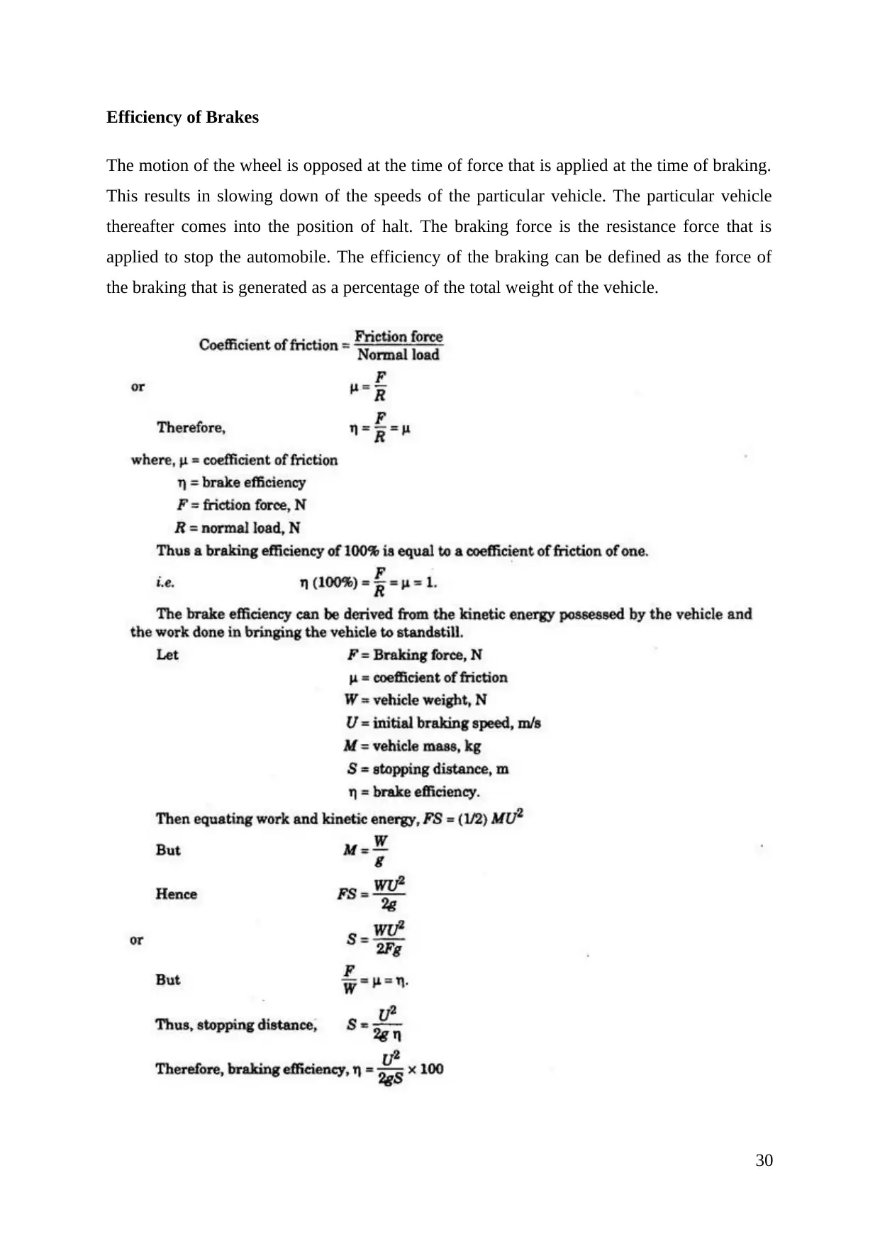
The motion of the wheel is opposed at the time of force that is applied at the time of braking.
This results in slowing down of the speeds of the particular vehicle. The particular vehicle
thereafter comes into the position of halt. The braking force is the resistance force that is
applied to stop the automobile. The efficiency of the braking can be defined as the force of
the braking that is generated as a percentage of the total weight of the vehicle.
30
⊘ This is a preview!⊘
Do you want full access?
Subscribe today to unlock all pages.

Trusted by 1+ million students worldwide
(Source: What When How, 2018)
The range of the braking efficiency is always less than 100%. This is because of the road
adhesion that is insufficient. If the particular vehicle is on the down gradient then also the
efficiency of the Braking System will be less than 100%. The braking efficiency of the
particular vehicle is similar to the coefficient of the friction. The coefficient of friction can be
analysed with the help of frictional force between the two rubbing surfaces par normal load
between the particular two surfaces.
Drum Brake
Talking about the efficiency of the drum brake, these brakes are not so efficient as compared
to the other brakes. The reason behind less efficiency of the drum brake is that these brakes
used to overheat quickly. These brakes sometimes lose their stopping power. The overheating
of the drum brake is usually because of the design of the drum brakes (What When How,
2018). The efficiency of the hydraulic brake, the disc brake is usually more than the
efficiency of the drum brake. This is resulting in the use of disc brake more as compared to
drum brake. Drum brakes are non-self-adjusting (Shaik & Srinivas, 2012).
Hydraulic Brake
Heavy trucks use fluid actuated Braking System. These are the hydraulic Braking System.
The fluid that is used in the hydraulic braking system is incompressible in nature. There is the
very less force required from the driver side in the application of the hydraulic brake. The
pressure that is being produced in the master cylinder of the Hydraulic brake is used to same.
The application of the force by calliper on the rotor will be same (Sowjanya & Suresh, 2013).
There can be the situation in which biasing of this type of brake can be accomplished. In this
biasing front wheels gets 80% of the braking force. The Heat that is produced in the time off
friction is tolerated by the hydraulic system. This type of brake is more efficient as compared
to drum brake (What When How, 2018).
Disc Brake
Coming on the efficiency of the disc brake, these brakes are highly efficient. Stopping power
in the disc brake is more as compared to the drum brake. There is the situation of better heat
31
Paraphrase This Document
can be accomplished without removing the wheel. This is the advantage of using disc brake
more in the automobile. The disc brake is completely self-adjusting (Zhang, et. al., 2012).
Because of all such situation efficiency of the disc brakes are more as compared to drum
brake and another break.
Anti-Lock Brake system
The Anti-Lock Braking System is the safety feature that can be implemented to the Braking
System. Talking of the efficiency of the Anti-Lock brake system this system is the most
efficient braking system that can be installed to the automobiles. In the other type of brake
whether it is drum brake, hydraulic brake and disc brake the locking of the brake can be
possible. This can result in the total failure of the Braking System in the critical situation. But
with the implementation of the safety feature of Anti-Lock Braking System in the
automobile, the Locking Up of the brake will not be the situation. In this Braking System,
this is the feature that is making this type of braking system Advanced (Patra & Datta, 2012).
This type of braking system is electronically controlled. This type of braking system is
having an electronic control unit and a Hydraulic control unit. Both units are enhancing the
efficiency of the Anti-Lock Braking System. The signal of the acceleration of the wheel is
received in the electronically controlled unit of disc Braking System. The process of slowing
down and then halt position of the vehicle can be accomplished on the basis of this signal.
The whole process is accomplished without any lock and skid of the brake. In this way, it can
be said that the efficiency of this type of braking system that is installed in the vehicle used to
be highly efficient.
32
Drum Brake
The drum braking system is used in the normal Braking System. This type of braking system
is installed in the rear Wheels of the Ford cars. This type of braking system is also used in the
parking emergency brake (Koike, 2014). In the parking emergency brakes, a series of copper
cables are connected to a foot pedal or hand Lever of the particular Brake.
Hydraulic brake
The power of fluid can be used in a different perspective of Technology. This can be
analysed analysis of The Uses of the hydraulic system. If the pressure is applied to the
particular fluid then it can multiply it into the forces. This can be accomplished with the help
of Pascal Law. The hoist of thousands of Pounds can be accomplished with the help of this
technique (Nian, et. al., 2014). The hydraulic braking system is used in the hydraulic car lift.
The application of the small force on the 1 part of the Jack fluid used to lift a vehicle.
The hydraulic braking system is used in the cars, trucks and other automobiles. This type of
braking system is also used in the aeroplane. For slowing down of the aeroplane on the
runway these Brakes are used. The slowing down of the aeroplane can be accomplished with
the help of transferring the force that is applied to the hydraulic fluid. For compressing the
substance this hydraulic system is used.
Disc Brake
Disc brakes are quite popular. The application of the disc brake in the present time is vast.
Disc brakes are used in motorcycles and scooters. In the present time, all the scooter and
motorcycle are equipped with disc brakes. Disc brakes are also used in the power cycles that
are having the gears. Disc brakes are also used in the heavy vehicle. For stopping and slowing
down the different type of heavy vehicles disc brake are used in a wide range (Koike, 2014).
Disc brakes are also used in the reel and aircraft. Larger disc is used in the rails for the
braking system.
33
⊘ This is a preview!⊘
Do you want full access?
Subscribe today to unlock all pages.

Trusted by 1+ million students worldwide
that can stop the bikes and the vehicle instantly. The use of such type of in such type of
racing is done to avoid accidents.
Anti-Lock Brake System
The use of the Anti-Lock Braking System can be seen from time to time. Gabriel Voisin
developed this type of braking system in the year 1929 but it was developed by Bosch and
Mercedes Benz in 1936. The wide acceptance of this type of Braking System was evidenced
in 1971. This Braking System was applied in Toyota Crown. After that, just type of Braking
System was installed in the trucks of Fiat. In 1976 WABCO started to use such type of
Braking System in their vehicles. Bosch and Mercedes Benz from the starting when is
making system was formed is using and implementing this type of braking system technology
in their cars (Oleksowicz, et. al., 2013).
After that Honda, Ford, BMW all other companies started to use such type of braking system
in their car. In present time the wide acceptance of such type of Braking System is because of
the safety feature that which type of braking system used to provide. This helps in preventing
the accidents. In this way, this braking system is gained its popularity.
34
Paraphrase This Document
In the assessment part, there is the comparison of Brake on the basis of graphical analysis.
This graphical analysis provides the information by which comparison can be done on the
basis of relevant information. This makes the research project valid in nature. From the
research, it can be analysed to that different type of braking systems developed from the past
times. The intersection will be analysed that which will be the most suitable Braking System
for the present time automobiles.
Analysis 1
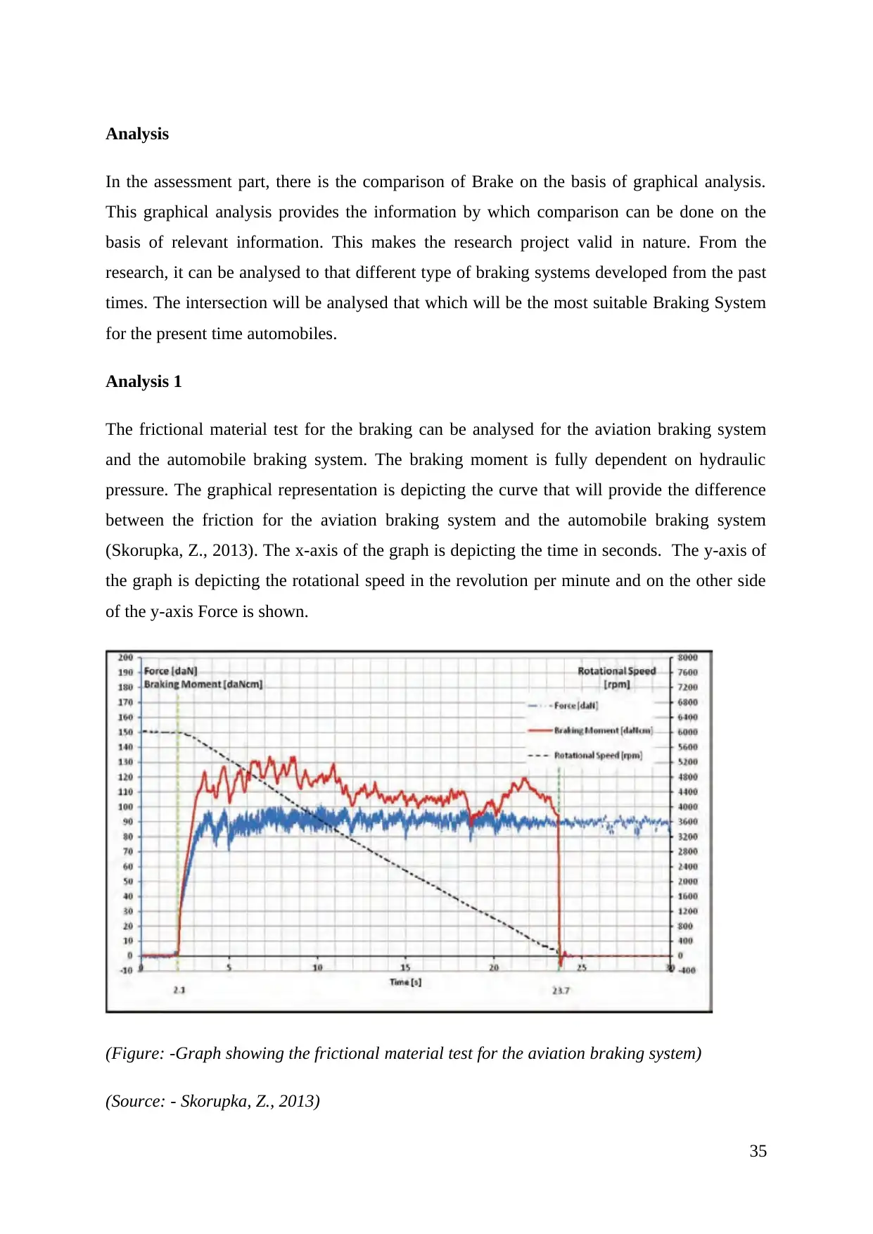
The frictional material test for the braking can be analysed for the aviation braking system
and the automobile braking system. The braking moment is fully dependent on hydraulic
pressure. The graphical representation is depicting the curve that will provide the difference
between the friction for the aviation braking system and the automobile braking system
(Skorupka, Z., 2013). The x-axis of the graph is depicting the time in seconds. The y-axis of
the graph is depicting the rotational speed in the revolution per minute and on the other side
of the y-axis Force is shown.
(Figure: -Graph showing the frictional material test for the aviation braking system)
(Source: - Skorupka, Z., 2013)
35
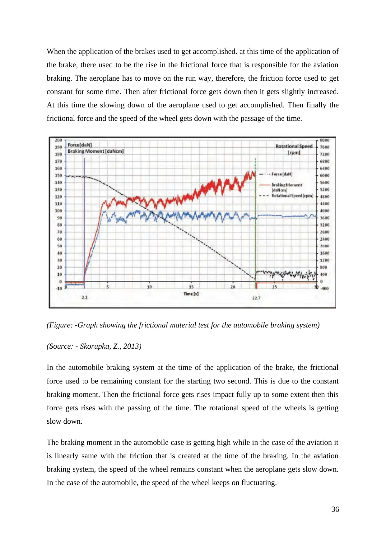
the brake, there used to be the rise in the frictional force that is responsible for the aviation
braking. The aeroplane has to move on the run way, therefore, the friction force used to get
constant for some time. Then after frictional force gets down then it gets slightly increased.
At this time the slowing down of the aeroplane used to get accomplished. Then finally the
frictional force and the speed of the wheel gets down with the passage of the time.
(Figure: -Graph showing the frictional material test for the automobile braking system)
(Source: - Skorupka, Z., 2013)
In the automobile braking system at the time of the application of the brake, the frictional
force used to be remaining constant for the starting two second. This is due to the constant
braking moment. Then the frictional force gets rises impact fully up to some extent then this
force gets rises with the passing of the time. The rotational speed of the wheels is getting
slow down.
The braking moment in the automobile case is getting high while in the case of the aviation it
is linearly same with the friction that is created at the time of the braking. In the aviation
braking system, the speed of the wheel remains constant when the aeroplane gets slow down.
In the case of the automobile, the speed of the wheel keeps on fluctuating.
36
⊘ This is a preview!⊘
Do you want full access?
Subscribe today to unlock all pages.

Trusted by 1+ million students worldwide
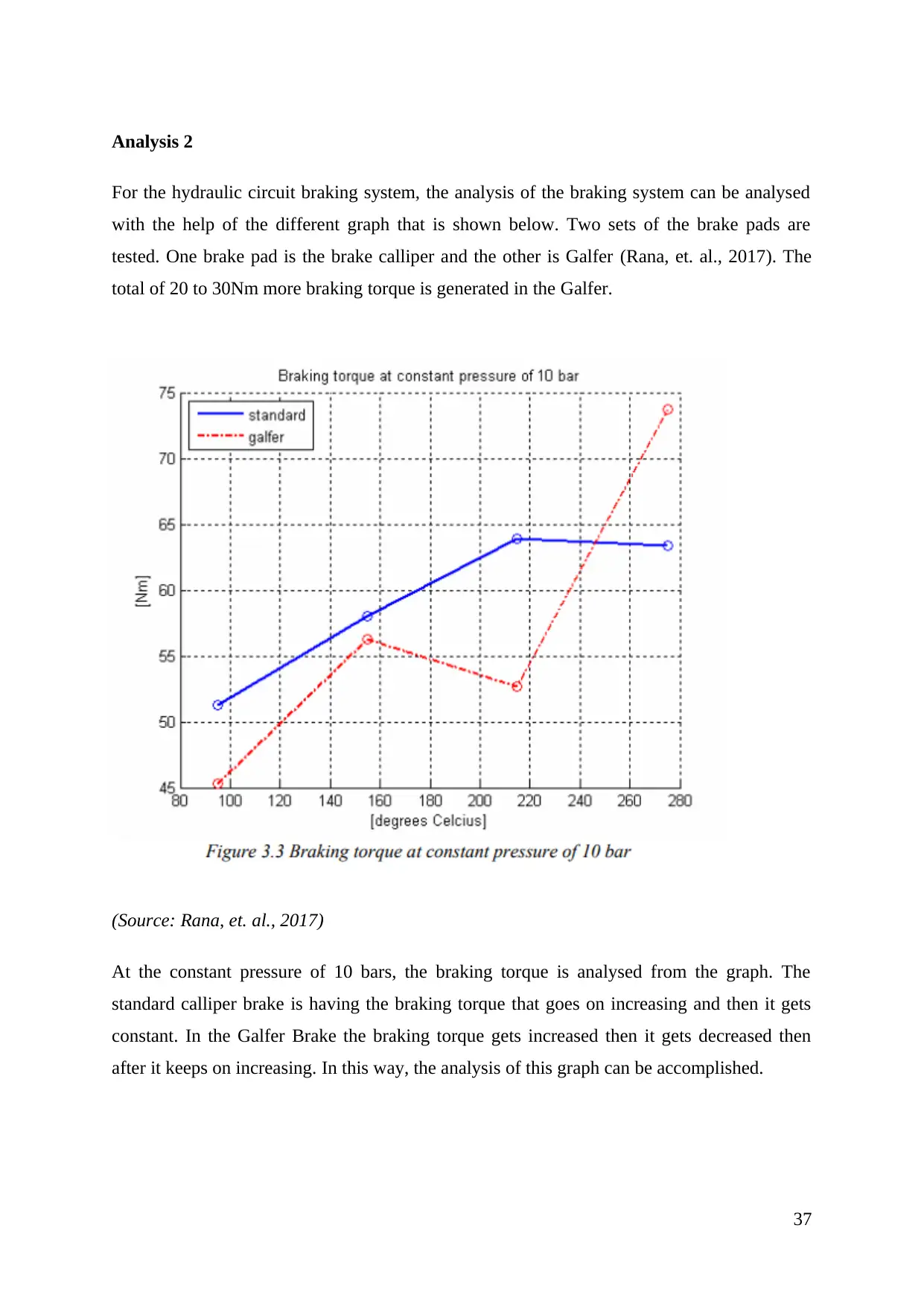
For the hydraulic circuit braking system, the analysis of the braking system can be analysed
with the help of the different graph that is shown below. Two sets of the brake pads are
tested. One brake pad is the brake calliper and the other is Galfer (Rana, et. al., 2017). The
total of 20 to 30Nm more braking torque is generated in the Galfer.
(Source: Rana, et. al., 2017)
At the constant pressure of 10 bars, the braking torque is analysed from the graph. The
standard calliper brake is having the braking torque that goes on increasing and then it gets
constant. In the Galfer Brake the braking torque gets increased then it gets decreased then
after it keeps on increasing. In this way, the analysis of this graph can be accomplished.
37
Paraphrase This Document
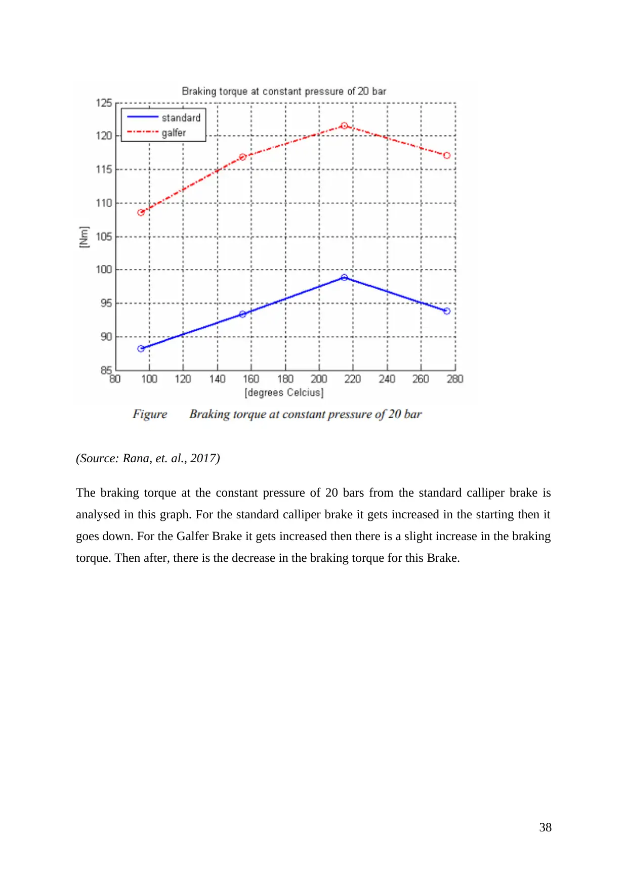
The braking torque at the constant pressure of 20 bars from the standard calliper brake is
analysed in this graph. For the standard calliper brake it gets increased in the starting then it
goes down. For the Galfer Brake it gets increased then there is a slight increase in the braking
torque. Then after, there is the decrease in the braking torque for this Brake.
38
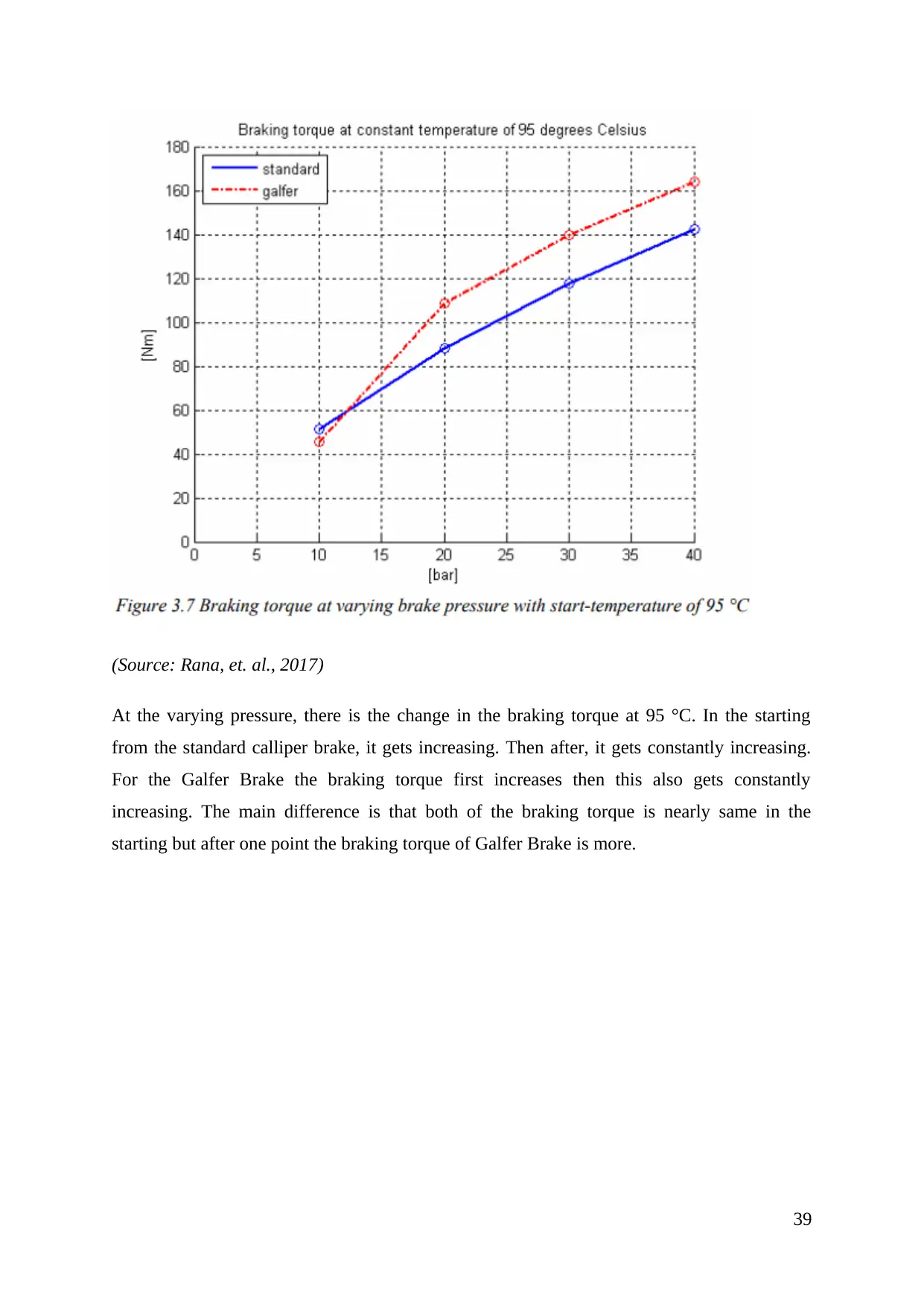
At the varying pressure, there is the change in the braking torque at 95 °C. In the starting
from the standard calliper brake, it gets increasing. Then after, it gets constantly increasing.
For the Galfer Brake the braking torque first increases then this also gets constantly
increasing. The main difference is that both of the braking torque is nearly same in the
starting but after one point the braking torque of Galfer Brake is more.
39
⊘ This is a preview!⊘
Do you want full access?
Subscribe today to unlock all pages.

Trusted by 1+ million students worldwide
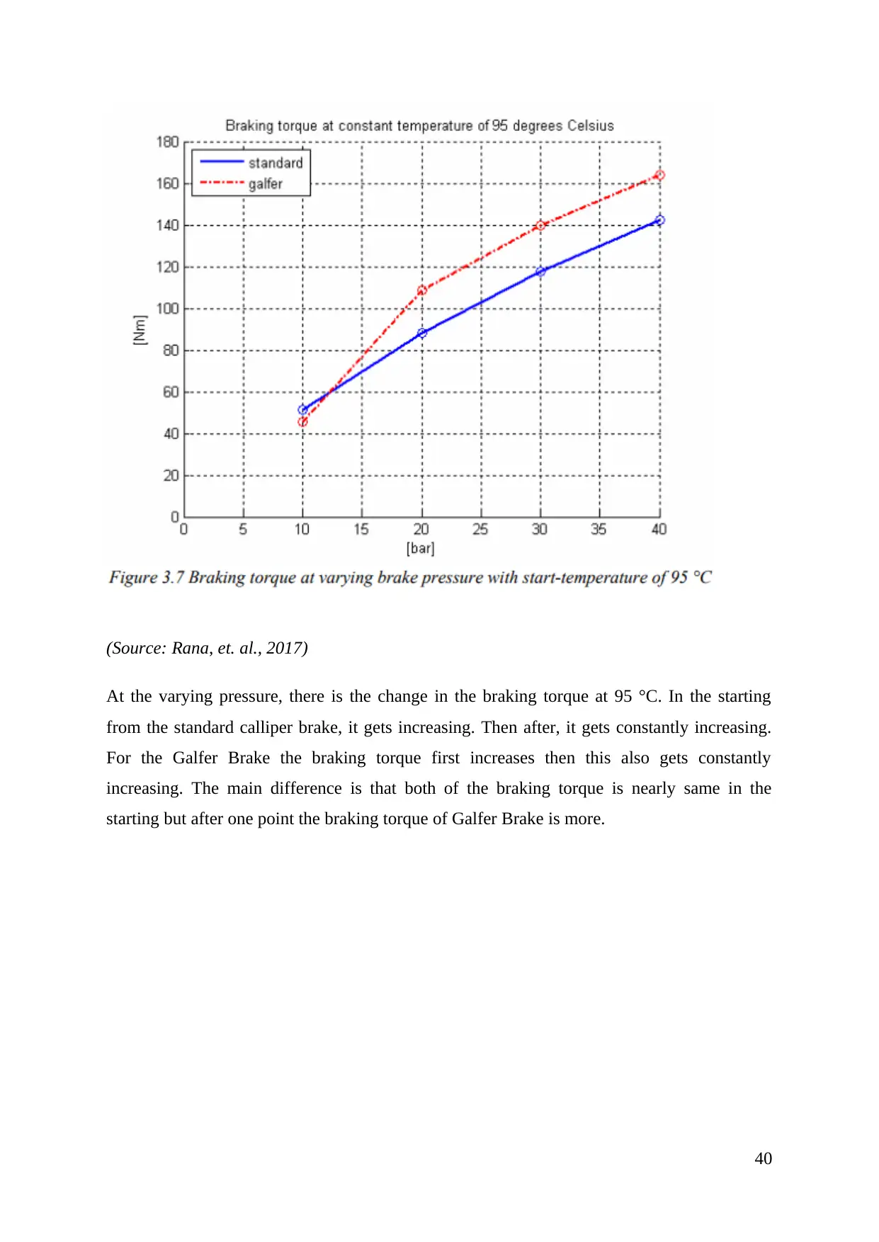
At the varying pressure, there is the change in the braking torque at 95 °C. In the starting
from the standard calliper brake, it gets increasing. Then after, it gets constantly increasing.
For the Galfer Brake the braking torque first increases then this also gets constantly
increasing. The main difference is that both of the braking torque is nearly same in the
starting but after one point the braking torque of Galfer Brake is more.
40
Paraphrase This Document
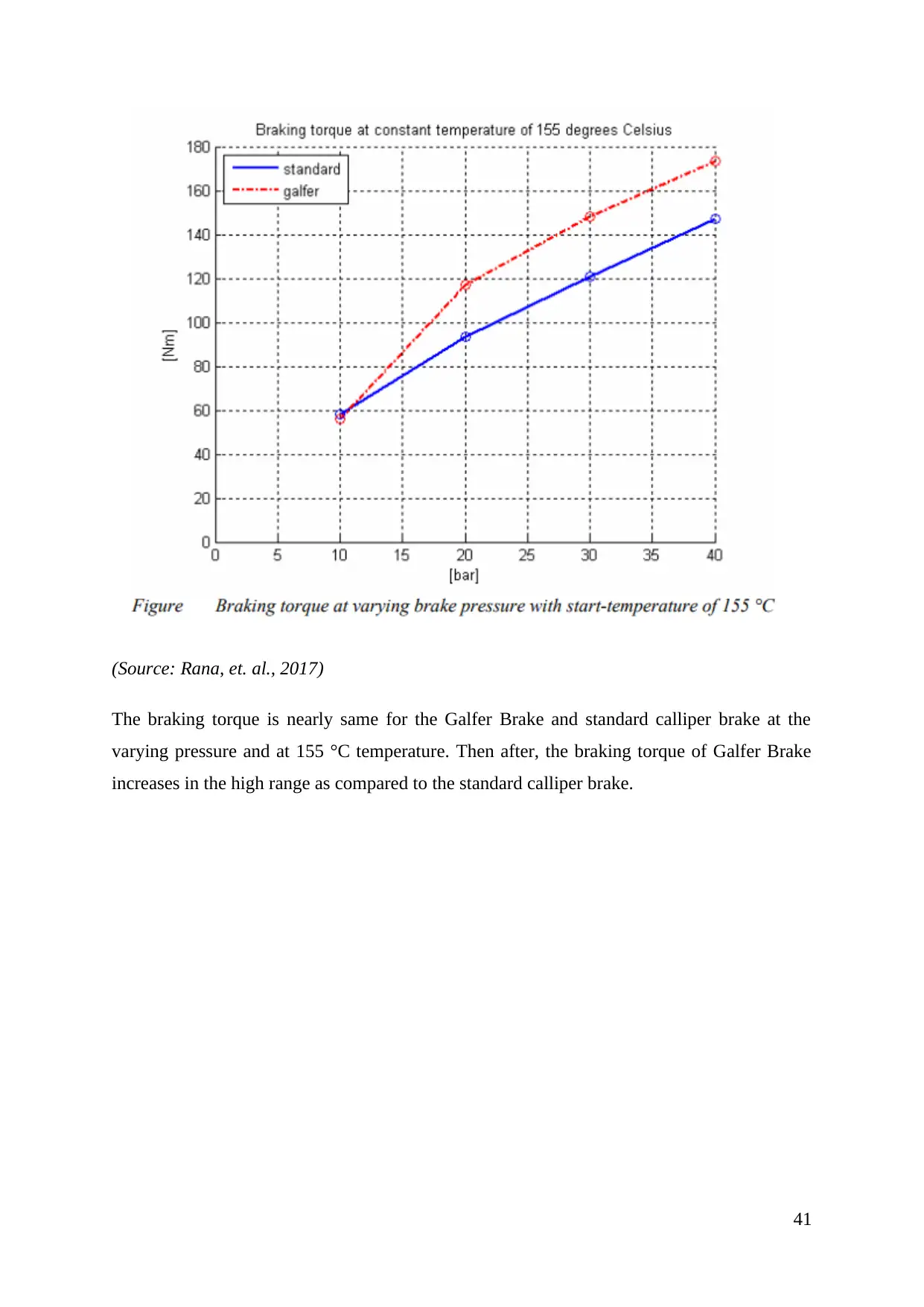
The braking torque is nearly same for the Galfer Brake and standard calliper brake at the
varying pressure and at 155 °C temperature. Then after, the braking torque of Galfer Brake
increases in the high range as compared to the standard calliper brake.
41
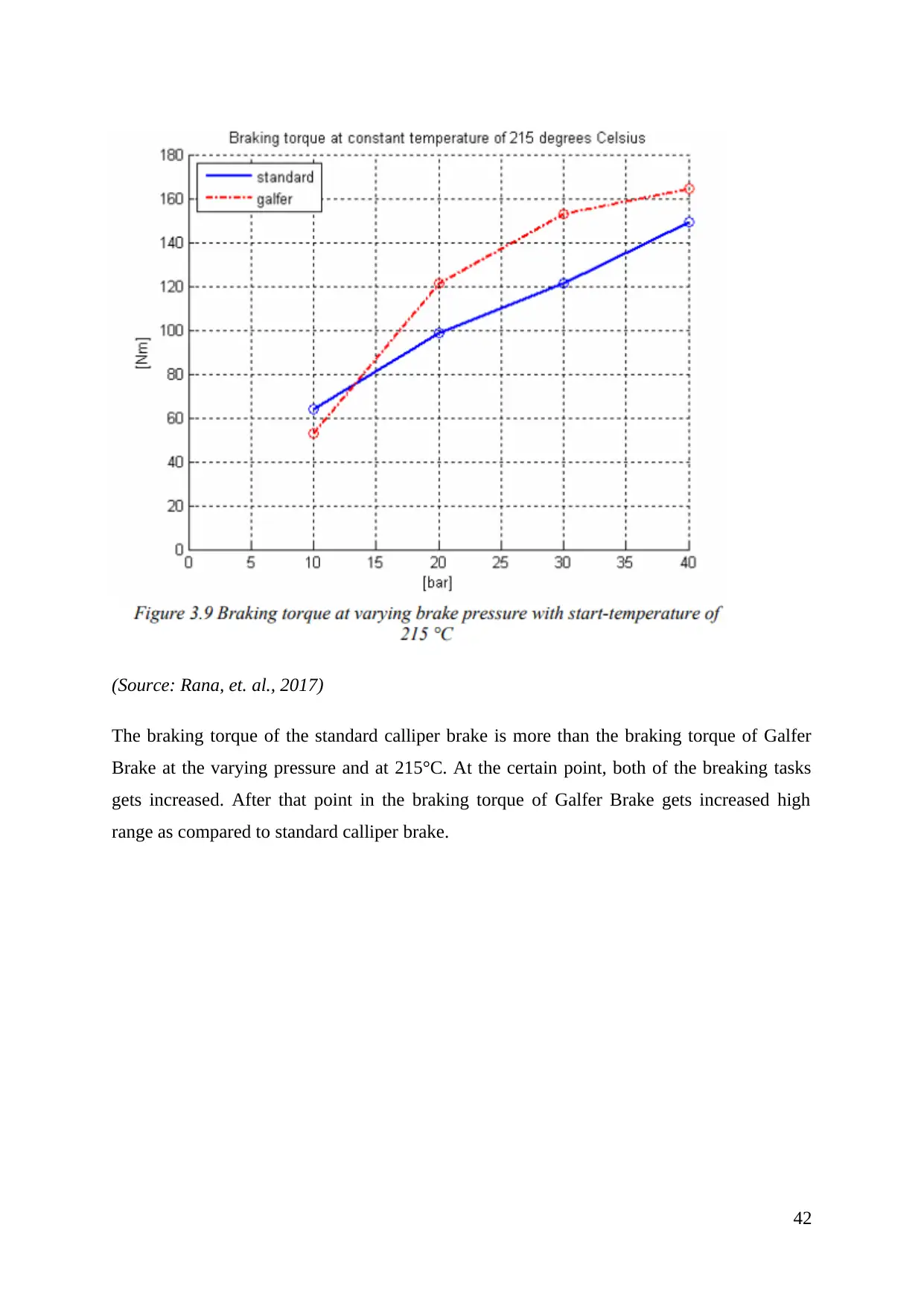
The braking torque of the standard calliper brake is more than the braking torque of Galfer
Brake at the varying pressure and at 215°C. At the certain point, both of the breaking tasks
gets increased. After that point in the braking torque of Galfer Brake gets increased high
range as compared to standard calliper brake.
42
⊘ This is a preview!⊘
Do you want full access?
Subscribe today to unlock all pages.

Trusted by 1+ million students worldwide
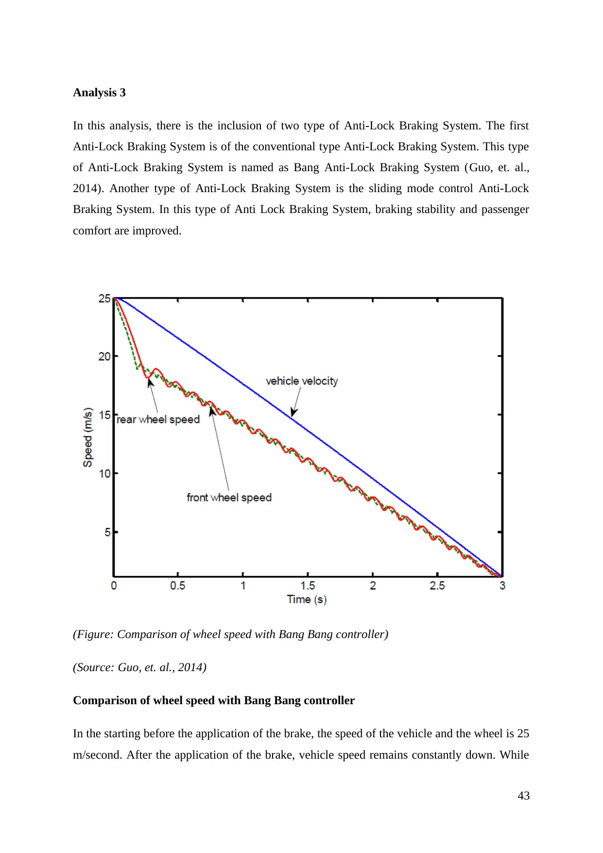
In this analysis, there is the inclusion of two type of Anti-Lock Braking System. The first
Anti-Lock Braking System is of the conventional type Anti-Lock Braking System. This type
of Anti-Lock Braking System is named as Bang Anti-Lock Braking System (Guo, et. al.,
2014). Another type of Anti-Lock Braking System is the sliding mode control Anti-Lock
Braking System. In this type of Anti Lock Braking System, braking stability and passenger
comfort are improved.
(Figure: Comparison of wheel speed with Bang Bang controller)
(Source: Guo, et. al., 2014)
Comparison of wheel speed with Bang Bang controller
In the starting before the application of the brake, the speed of the vehicle and the wheel is 25
m/second. After the application of the brake, vehicle speed remains constantly down. While
43
Paraphrase This Document
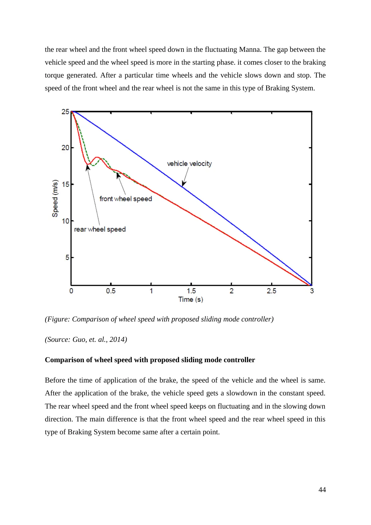
vehicle speed and the wheel speed is more in the starting phase. it comes closer to the braking
torque generated. After a particular time wheels and the vehicle slows down and stop. The
speed of the front wheel and the rear wheel is not the same in this type of Braking System.
(Figure: Comparison of wheel speed with proposed sliding mode controller)
(Source: Guo, et. al., 2014)
Comparison of wheel speed with proposed sliding mode controller
Before the time of application of the brake, the speed of the vehicle and the wheel is same.
After the application of the brake, the vehicle speed gets a slowdown in the constant speed.
The rear wheel speed and the front wheel speed keeps on fluctuating and in the slowing down
direction. The main difference is that the front wheel speed and the rear wheel speed in this
type of Braking System become same after a certain point.
44
The direction stability can be maintained at the time of Anti-Lock Braking System. This is
the feature that provides the ease to the driver in the critical situation. The stability can be
enhanced because of the control of steering at the time of braking. In this way, the safety
feature which is effective in nature is the output of this type of Braking System. The brake
fluid pressure can be changed automatically in this type of Braking System. This used to be
accomplished at every wheel of the vehicle. This helps in maintaining the brake performance
for which the Anti-Lock Braking System is installed in the vehicles. The unwanted
turbulence shockwaves can be absorbed. Modulating the pulses is also perform them. This is
the feature that provides the permission of turning of the wheel even in maximum brake
pressure. In this way finally, it can be concluded that this type of braking system is having
more efficiency as compared to all type of brake.
45
⊘ This is a preview!⊘
Do you want full access?
Subscribe today to unlock all pages.

Trusted by 1+ million students worldwide
1. Ajibola, O. O., Adewuyi, B. O., & Oloruntoba, D. T. (2014). Wear behaviour of
sand cast eutectic Al-Si alloy in hydraulic brake fluid. International Journal of
Innovation and Applied Studies, 6(3), 420.
2. Bhandari, R., Patil, S., & Singh, R. K. (2012). Surface prediction and control
algorithms for anti-lock brake system. Transportation research part C: emerging
technologies, 21(1), 181-195.
3. Byun, H. S. (2017). U.S. Patent No. 9,815,468. Washington, DC: U.S. Patent and
Trademark Office.
4. Coetzee, R. (2015). Custom design comes to life: trailers. Transport World
Africa, 13(2), 14-15.
5. Crippa, C., & Tupputi, A. (2014). U.S. Patent No. 8,794,397. Washington, DC:
U.S. Patent and Trademark Office.
6. Entezami, M., Hillmansen, S., Weston, P. and Papaelias, M.P., 2012. Fault
detection and diagnosis within a wind turbine mechanical braking system using
condition monitoring. Renewable energy, 47, pp.175-182.
7. EZAWA, K., & RAKSINCHAROENSAK, P. (2014, August). 2B12 Hazard-
anticipatory collision avoidance braking assistance sytem based on pedestrian motion
prediction (The 12th International Conference on Motion and Vibration Control).
In The Proceedings of the Symposium on the Motion and Vibration Control
2014.12 (pp. _2B12-1_). The Japan Society of Mechanical Engineers.
8. Guo, J., Jian, X., & Lin, G. (2014). Performance evaluation of an anti-lock
braking system for electric vehicles with a fuzzy sliding mode
controller. Energies, 7(10), 6459-6476.
9. Hanna, M. D., & Schroth, J. G. (2012). U.S. Patent No. 8,245,758. Washington,
DC: U.S. Patent and Trademark Office.
46
Paraphrase This Document
energy-regenerative system. Automation in Construction, 22, 444-458.
11. Holme, J. D., Ferdani, P., & Patel, N. (2012). U.S. Patent No. 8,215,461.
Washington, DC: U.S. Patent and Trademark Office.
12. Jegadeeshwaran, R., & Sugumaran, V. (2013). Comparative study of decision tree
classifier and best first tree classifier for fault diagnosis of automobile hydraulic brake
system using statistical features. Measurement, 46(9), 3247-3260.
13. Keppy, B. (2018). U.S. Patent No. 9,870,651. Washington, DC: U.S. Patent and
Trademark Office.
14. Koike, M. (2014). U.S. Patent No. 8,678,975. Washington, DC: U.S. Patent and
Trademark Office.
15. Kümmel, K., Keil, C., Marschner, H., Piehler, C., & Socolov, S. (2018). U.S.
Patent No. 9,890,823. Washington, DC: U.S. Patent and Trademark Office.
16. Lv, C., Zhang, J., Li, Y., Sun, D., & Yuan, Y. (2014). Hardware-in-the-loop
simulation of pressure-difference-limiting modulation of the hydraulic brake for
regenerative braking control of electric vehicles. Proceedings of the Institution of
Mechanical Engineers, Part D: Journal of Automobile Engineering, 228(6), 649-662.
17. Midgley, W. J. B., Cathcart, H., & Cebon, D. (2013). Modelling of hydraulic
regenerative braking systems for heavy vehicles. Proceedings of the Institution of
Mechanical Engineers, Part D: Journal of Automobile Engineering, 227(7), 1072-
1084.
18. Monopoli, M., & Giordano, D. (2012). U.S. Patent No. 8,286,762. Washington,
DC: U.S. Patent and Trademark Office.
19. Nian, X., Peng, F., & Zhang, H. (2014). Regenerative braking system of electric
vehicle driven by brushless DC motor. IEEE Transactions on Industrial
Electronics, 61(10), 5798-5808.
20. Oleksowicz, S. A., Burnham, K. J., Southgate, A., McCoy, C., Waite, G.,
Hardwick, G., ... & McMurran, R. (2013). Regenerative braking strategies, vehicle
47
dynamics, 51(5), 684-699.
21. Park, S. Y., & Choi, S. H. (2013). U.S. Patent No. 8,430,459. Washington, DC:
U.S. Patent and Trademark Office.
22. Patra, N., & Datta, K. (2012, August). Sliding mode controller for wheel-slip
control of anti-lock braking system. In Advanced Communication Control and
Computing Technologies (ICACCCT), 2012 IEEE International Conference on (pp.
385-391). IEEE.
23. Rana, R. H., Jakhiya, N. H., Savani, A. K., & Bhalodi, A. K. (2017). OPTIMUM
DESIGN OF BRAKING SYSTEM FOR A FORMULA 3 RACE CARS WITH
NUMERIC COMPUTATIONS AND THERMAL ANALYSIS.
24. Rehman, A., Das, S., & Dixit, G. (2012). Analysis of stir die cast Al–SiC
composite brake drums based on coefficient of friction. Tribology International, 51,
36-41.
25. Riaz, S., & Khan, L. (2016, January). Adaptive soft computing strategy for ride
quality improvement with anti-lock braking system. In Applied Sciences and
Technology (IBCAST), 2016 13th International Bhurban Conference on (pp. 280-
285). IEEE.
26. Riese, C., Verhagen, A., Schroeter, S., & Gauterin, F. (2017). Comparison of a
State of the Art Hydraulic Brake System with a Decentralized Hydraulic Brake System
Concept for Electric Vehicles (No. 2017-01-2515). SAE Technical Paper.
27. Röhling, W. (2016). U.S. Patent Application No. 14/541,752.
28. Saravanan, B. Design and Analysis of Disc Brake Rotor. International Journal of
Applied Engineering Research, 10(19), 2015.
29. Shaik, A. F. B., & Srinivas, C. L. (2012). Structural and thermal analysis of disc
brake with and without crossdrilled rotar of race car. International Journal of
Advanced Engineering Research and Studies, 1(4), 39-43.
48
⊘ This is a preview!⊘
Do you want full access?
Subscribe today to unlock all pages.

Trusted by 1+ million students worldwide
invasive spoofing attacks for anti-lock braking systems. In International Workshop on
Cryptographic Hardware and Embedded Systems (pp. 55-72). Springer, Berlin,
Heidelberg.
31. Shoukry, Y., Martin, P., Tabuada, P., & Srivastava, M. (2013, August). Non-
invasive spoofing attacks for anti-lock braking systems. In International Workshop on
Cryptographic Hardware and Embedded Systems (pp. 55-72). Springer, Berlin,
Heidelberg.
32. Singh, A. K., & Sharma, A. K. (2014, November). Parameter identification of
eddy current braking sytem for various applications. In Computational Intelligence on
Power, Energy and Controls with their impact on Humanity (CIPECH), 2014
Innovative Applications of (pp. 191-195). IEEE.
33. Skorupka, Z. (2013). Braking moment comparison and analysis for various brake
designs using results from sample and full scale friction material tests. Journal of
KONES, 20.
34. Sowjanya, K., & Suresh, S. (2013). Structural analysis of disc brake
rotor. International Journal of Computer Trends and Technology (IJCTT), 4(7), 2295-
2298.
35. Wang, Z., Yu, L., Wang, Y., You, C., Ma, L., & Song, J. (2013). Prototype of
distributed electro-hydraulic braking system and its fail-safe control strategy (No.
2013-01-2066). SAE Technical Paper.
36. What When How. (2018). Braking System. [Online] What When How. Available
at: http://what-when-how.com/automobile/braking-system-automobile/. [Accessed
On: 10 May 2018]
37. Yim, S., Jeon, K., & Yi, K. (2012). An investigation into vehicle rollover
prevention by coordinated control of active anti-roll bar and electronic stability
program. International Journal of Control, Automation and Systems, 10(2), 275-287.
38. Zhang, J., Lv, C., Gou, J., & Kong, D. (2012). Cooperative control of regenerative
braking and hydraulic braking of an electrified passenger car. Proceedings of the
49
Paraphrase This Document
Engineering, 226(10), 1289-1302.
39. Zhao, S., Tian, M., Zhang, S., & Li, J. (2013). Regenerative Braking Experiment
Evaluation of Hybrid Electric Vehicle. International Journal of Digital Content
Technology and its Applications, 7(5), 976.
50
Your All-in-One AI-Powered Toolkit for Academic Success.
+13062052269
info@desklib.com
Available 24*7 on WhatsApp / Email
![[object Object]](/_next/static/media/star-bottom.7253800d.svg)
© 2024 | Zucol Services PVT LTD | All rights reserved.


