Conceptual Design of Sydney Harbour Bridge: Stakeholders and Systems
VerifiedAdded on 2023/01/03
|12
|3142
|27
Report
AI Summary
This report offers a detailed examination of the Sydney Harbour Bridge, focusing on its conceptual design, the needs of its stakeholders, and its system requirements. The introduction provides context by comparing it to other notable bridges. The report then delves into the stakeholders' needs, encompassing the expectations of major investors and shareholders. The conceptual design process is outlined, including business needs, system requirements, and system-level synthesis, to provide a comprehensive understanding of the design process. The system requirements section details the guidelines and configurations necessary for the bridge's efficient operation. The report also assesses the learning outcomes, emphasizing the processes and management of the bridge's system life cycle. This includes inspections, maintenance, and the roles of various contractors and specialists involved in ensuring the bridge's longevity and safety. The report concludes with a summary of the bridge's key features, including its dimensions and structural components.
Bridge 1
CONCEPTUAL DESIGN OF BRIDGE
By Name
Course
Instructor
Institution
Location
Date
Table of Contents
1
CONCEPTUAL DESIGN OF BRIDGE
By Name
Course
Instructor
Institution
Location
Date
Table of Contents
1
Paraphrase This Document
Need a fresh take? Get an instant paraphrase of this document with our AI Paraphraser
Bridge 2
INTRODUCTION.....................................................................................................................................3
STAKEHOLDERS’ NEEDS.....................................................................................................................3
CONCEPTUAL DESIGN PROCESS......................................................................................................4
Business needs and requirement...........................................................................................................4
System requirement...............................................................................................................................5
System-level synthesis............................................................................................................................7
System design review.............................................................................................................................8
SYSTEM REQUIREMENT.....................................................................................................................8
LEARNING OUTCOME ASSESSED.....................................................................................................8
CONCLUSION........................................................................................................................................11
REFERENCES........................................................................................................................................12
2
Bridge 3
INTRODUCTION
Sydney Bridge among the few bridges that make the city to be known around the world. It is
made of steel, situated in Sydney and crosses port of Jackson. British firm Dorman Long won
the tender of designing an arch bridge which was completed and opened 10 years later. The
bridge was created to hold 6 traffic lanes: 2 lanes for the trains, 2 footpaths and two lanes for
trams. There was the idea of building the Sydney Bridge as cantilever bridge which was
approved by the NSW Legislative Assembly but the council of legislation disagreed since it was
the realized that funds should be channeled into war effort. After World war one, Bradfield
returned from looking the tenders abroad with the idea of arch bridge design.
The arch bridge design was approved since it was cost-effective and stronger compared to other
proposed solutions. The building of the bridge occurred at the same period of construction of the
underground railway system in Sydney hence the Bridge was conceived to accommodate the
railway traffic also. This report illustrates the conceptual design, stakeholders need, and system
requirement of the Sydney Harbor Bridge. The Hong Kong Bridge consists of 3 artificial inlets,
one submarine tunnel and continued 3 cabled bridges.
STAKEHOLDERS’ NEEDS
This entails the expectations of the major shareholders and investors involved in the construction
and the bridge design. It represents the views of business users, acquirers and other stakeholders
as they relate to opportunity. The building of the bridge was opinionated by the bridge of Hell
Gate in the New York and become the tallest structure worldwide and sixth longest in terms of
spanning. The main stakeholder was British Firm, Midddlesbrough. The original contractor of
the bridge was John Bradfield but Sir Ralph Freeman was the one who was selected by the
company to build the bridge. The project engineer was Gilbert Roberts and Georges Camille was
3
⊘ This is a preview!⊘
Do you want full access?
Subscribe today to unlock all pages.
Trusted by 1+ million students worldwide
Bridge 4
the consulting engineer. The decision to construct the Sydney Bridge was to join the south and
north shore of Sydney harbour. Ferry organizations were not keen on harbour crossing and had a
monopoly of getting people and goods across the harbour. There was more traffic of ferry in the
harbour and royal commission determined that the bridge should be constructed between the two
banks (Avşar, 2011).
The Hong Kong Bridge was built to improve flow of goods, labour and market worldwide. The
bridge was also to minimize traffics and congestions, improve tourisms, reduce carbon
emissions, to improve networks of transport and create employment opportunities. The aim of
building Story Bridge was to reduce traffic congestion at the bridge if Victoria and also to create
job opportunities.
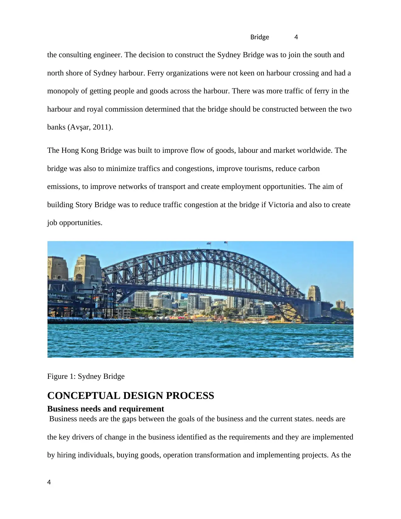
Figure 1: Sydney Bridge
CONCEPTUAL DESIGN PROCESS
Business needs and requirement
Business needs are the gaps between the goals of the business and the current states. needs are
the key drivers of change in the business identified as the requirements and they are implemented
by hiring individuals, buying goods, operation transformation and implementing projects. As the
4
the consulting engineer. The decision to construct the Sydney Bridge was to join the south and
north shore of Sydney harbour. Ferry organizations were not keen on harbour crossing and had a
monopoly of getting people and goods across the harbour. There was more traffic of ferry in the
harbour and royal commission determined that the bridge should be constructed between the two
banks (Avşar, 2011).
The Hong Kong Bridge was built to improve flow of goods, labour and market worldwide. The
bridge was also to minimize traffics and congestions, improve tourisms, reduce carbon
emissions, to improve networks of transport and create employment opportunities. The aim of
building Story Bridge was to reduce traffic congestion at the bridge if Victoria and also to create
job opportunities.
Figure 1: Sydney Bridge
CONCEPTUAL DESIGN PROCESS
Business needs and requirement
Business needs are the gaps between the goals of the business and the current states. needs are
the key drivers of change in the business identified as the requirements and they are implemented
by hiring individuals, buying goods, operation transformation and implementing projects. As the
4
Paraphrase This Document
Need a fresh take? Get an instant paraphrase of this document with our AI Paraphraser
Bridge 5
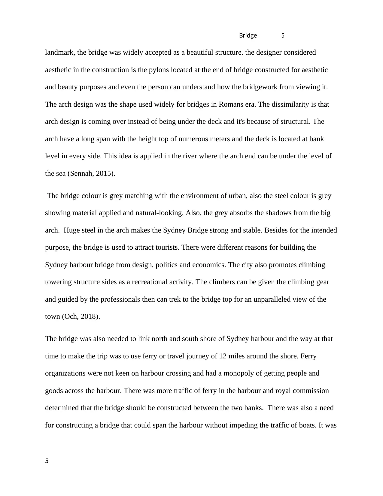
landmark, the bridge was widely accepted as a beautiful structure. the designer considered
aesthetic in the construction is the pylons located at the end of bridge constructed for aesthetic
and beauty purposes and even the person can understand how the bridgework from viewing it.
The arch design was the shape used widely for bridges in Romans era. The dissimilarity is that
arch design is coming over instead of being under the deck and it's because of structural. The
arch have a long span with the height top of numerous meters and the deck is located at bank
level in every side. This idea is applied in the river where the arch end can be under the level of
the sea (Sennah, 2015).
The bridge colour is grey matching with the environment of urban, also the steel colour is grey
showing material applied and natural-looking. Also, the grey absorbs the shadows from the big
arch. Huge steel in the arch makes the Sydney Bridge strong and stable. Besides for the intended
purpose, the bridge is used to attract tourists. There were different reasons for building the
Sydney harbour bridge from design, politics and economics. The city also promotes climbing
towering structure sides as a recreational activity. The climbers can be given the climbing gear
and guided by the professionals then can trek to the bridge top for an unparalleled view of the
town (Och, 2018).
The bridge was also needed to link north and south shore of Sydney harbour and the way at that
time to make the trip was to use ferry or travel journey of 12 miles around the shore. Ferry
organizations were not keen on harbour crossing and had a monopoly of getting people and
goods across the harbour. There was more traffic of ferry in the harbour and royal commission
determined that the bridge should be constructed between the two banks. There was also a need
for constructing a bridge that could span the harbour without impeding the traffic of boats. It was
5
Bridge 6
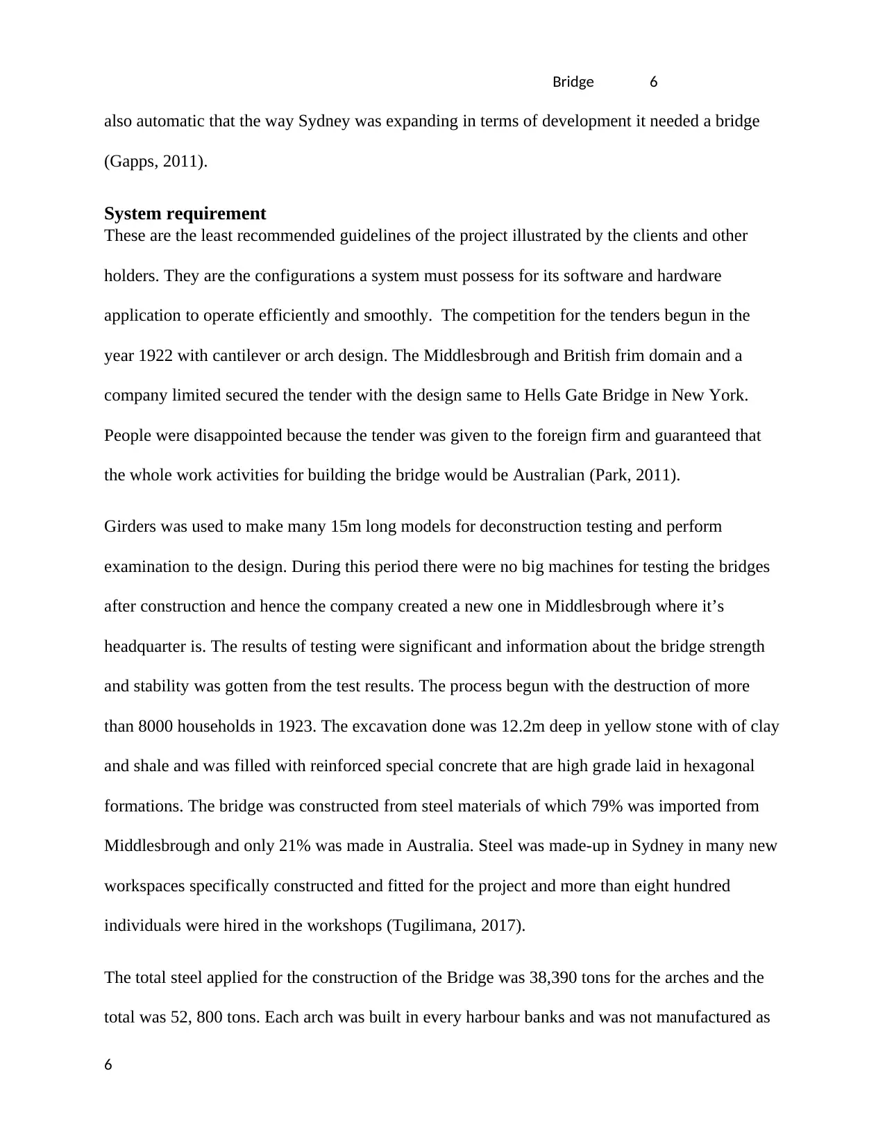
also automatic that the way Sydney was expanding in terms of development it needed a bridge
(Gapps, 2011).
System requirement
These are the least recommended guidelines of the project illustrated by the clients and other
holders. They are the configurations a system must possess for its software and hardware
application to operate efficiently and smoothly. The competition for the tenders begun in the
year 1922 with cantilever or arch design. The Middlesbrough and British frim domain and a
company limited secured the tender with the design same to Hells Gate Bridge in New York.
People were disappointed because the tender was given to the foreign firm and guaranteed that
the whole work activities for building the bridge would be Australian (Park, 2011).
Girders was used to make many 15m long models for deconstruction testing and perform
examination to the design. During this period there were no big machines for testing the bridges
after construction and hence the company created a new one in Middlesbrough where it’s
headquarter is. The results of testing were significant and information about the bridge strength
and stability was gotten from the test results. The process begun with the destruction of more
than 8000 households in 1923. The excavation done was 12.2m deep in yellow stone with of clay
and shale and was filled with reinforced special concrete that are high grade laid in hexagonal
formations. The bridge was constructed from steel materials of which 79% was imported from
Middlesbrough and only 21% was made in Australia. Steel was made-up in Sydney in many new
workspaces specifically constructed and fitted for the project and more than eight hundred
individuals were hired in the workshops (Tugilimana, 2017).
The total steel applied for the construction of the Bridge was 38,390 tons for the arches and the
total was 52, 800 tons. Each arch was built in every harbour banks and was not manufactured as
6
⊘ This is a preview!⊘
Do you want full access?
Subscribe today to unlock all pages.
Trusted by 1+ million students worldwide
Bridge 7
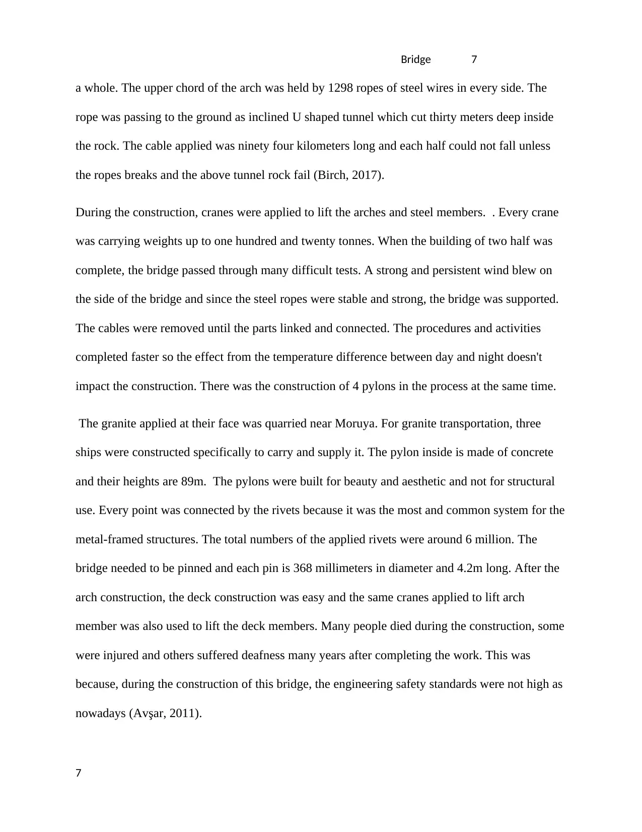
a whole. The upper chord of the arch was held by 1298 ropes of steel wires in every side. The
rope was passing to the ground as inclined U shaped tunnel which cut thirty meters deep inside
the rock. The cable applied was ninety four kilometers long and each half could not fall unless
the ropes breaks and the above tunnel rock fail (Birch, 2017).
During the construction, cranes were applied to lift the arches and steel members. . Every crane
was carrying weights up to one hundred and twenty tonnes. When the building of two half was
complete, the bridge passed through many difficult tests. A strong and persistent wind blew on
the side of the bridge and since the steel ropes were stable and strong, the bridge was supported.
The cables were removed until the parts linked and connected. The procedures and activities
completed faster so the effect from the temperature difference between day and night doesn't
impact the construction. There was the construction of 4 pylons in the process at the same time.
The granite applied at their face was quarried near Moruya. For granite transportation, three
ships were constructed specifically to carry and supply it. The pylon inside is made of concrete
and their heights are 89m. The pylons were built for beauty and aesthetic and not for structural
use. Every point was connected by the rivets because it was the most and common system for the
metal-framed structures. The total numbers of the applied rivets were around 6 million. The
bridge needed to be pinned and each pin is 368 millimeters in diameter and 4.2m long. After the
arch construction, the deck construction was easy and the same cranes applied to lift arch
member was also used to lift the deck members. Many people died during the construction, some
were injured and others suffered deafness many years after completing the work. This was
because, during the construction of this bridge, the engineering safety standards were not high as
nowadays (Avşar, 2011).
7
Paraphrase This Document
Need a fresh take? Get an instant paraphrase of this document with our AI Paraphraser
Bridge 8
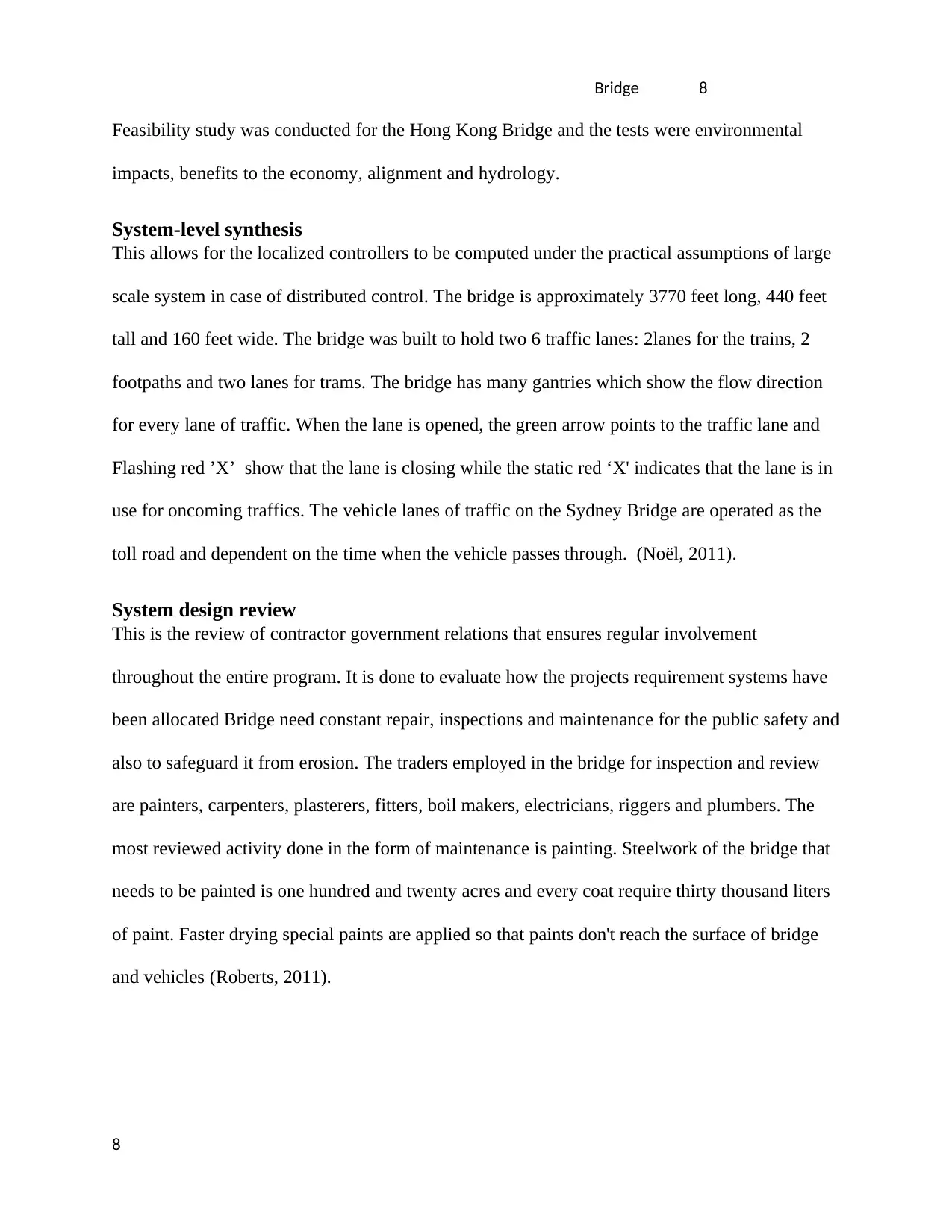
Feasibility study was conducted for the Hong Kong Bridge and the tests were environmental
impacts, benefits to the economy, alignment and hydrology.
System-level synthesis
This allows for the localized controllers to be computed under the practical assumptions of large
scale system in case of distributed control. The bridge is approximately 3770 feet long, 440 feet
tall and 160 feet wide. The bridge was built to hold two 6 traffic lanes: 2lanes for the trains, 2
footpaths and two lanes for trams. The bridge has many gantries which show the flow direction
for every lane of traffic. When the lane is opened, the green arrow points to the traffic lane and
Flashing red ’X’ show that the lane is closing while the static red ‘X' indicates that the lane is in
use for oncoming traffics. The vehicle lanes of traffic on the Sydney Bridge are operated as the
toll road and dependent on the time when the vehicle passes through. (Noël, 2011).
System design review
This is the review of contractor government relations that ensures regular involvement
throughout the entire program. It is done to evaluate how the projects requirement systems have
been allocated Bridge need constant repair, inspections and maintenance for the public safety and
also to safeguard it from erosion. The traders employed in the bridge for inspection and review
are painters, carpenters, plasterers, fitters, boil makers, electricians, riggers and plumbers. The
most reviewed activity done in the form of maintenance is painting. Steelwork of the bridge that
needs to be painted is one hundred and twenty acres and every coat require thirty thousand liters
of paint. Faster drying special paints are applied so that paints don't reach the surface of bridge
and vehicles (Roberts, 2011).
8
Bridge 9
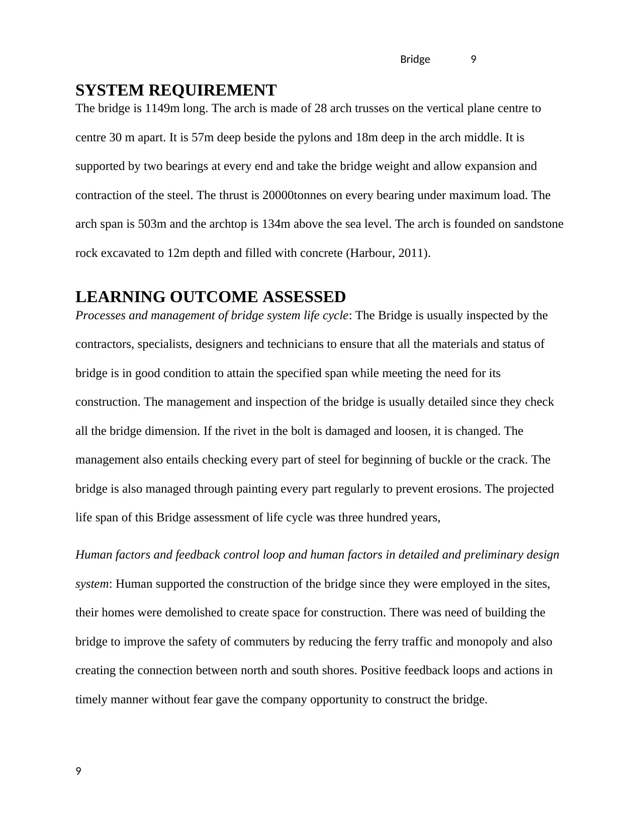
SYSTEM REQUIREMENT
The bridge is 1149m long. The arch is made of 28 arch trusses on the vertical plane centre to
centre 30 m apart. It is 57m deep beside the pylons and 18m deep in the arch middle. It is
supported by two bearings at every end and take the bridge weight and allow expansion and
contraction of the steel. The thrust is 20000tonnes on every bearing under maximum load. The
arch span is 503m and the archtop is 134m above the sea level. The arch is founded on sandstone
rock excavated to 12m depth and filled with concrete (Harbour, 2011).
LEARNING OUTCOME ASSESSED
Processes and management of bridge system life cycle: The Bridge is usually inspected by the
contractors, specialists, designers and technicians to ensure that all the materials and status of
bridge is in good condition to attain the specified span while meeting the need for its
construction. The management and inspection of the bridge is usually detailed since they check
all the bridge dimension. If the rivet in the bolt is damaged and loosen, it is changed. The
management also entails checking every part of steel for beginning of buckle or the crack. The
bridge is also managed through painting every part regularly to prevent erosions. The projected
life span of this Bridge assessment of life cycle was three hundred years,
Human factors and feedback control loop and human factors in detailed and preliminary design
system: Human supported the construction of the bridge since they were employed in the sites,
their homes were demolished to create space for construction. There was need of building the
bridge to improve the safety of commuters by reducing the ferry traffic and monopoly and also
creating the connection between north and south shores. Positive feedback loops and actions in
timely manner without fear gave the company opportunity to construct the bridge.
9
⊘ This is a preview!⊘
Do you want full access?
Subscribe today to unlock all pages.
Trusted by 1+ million students worldwide
Bridge 10
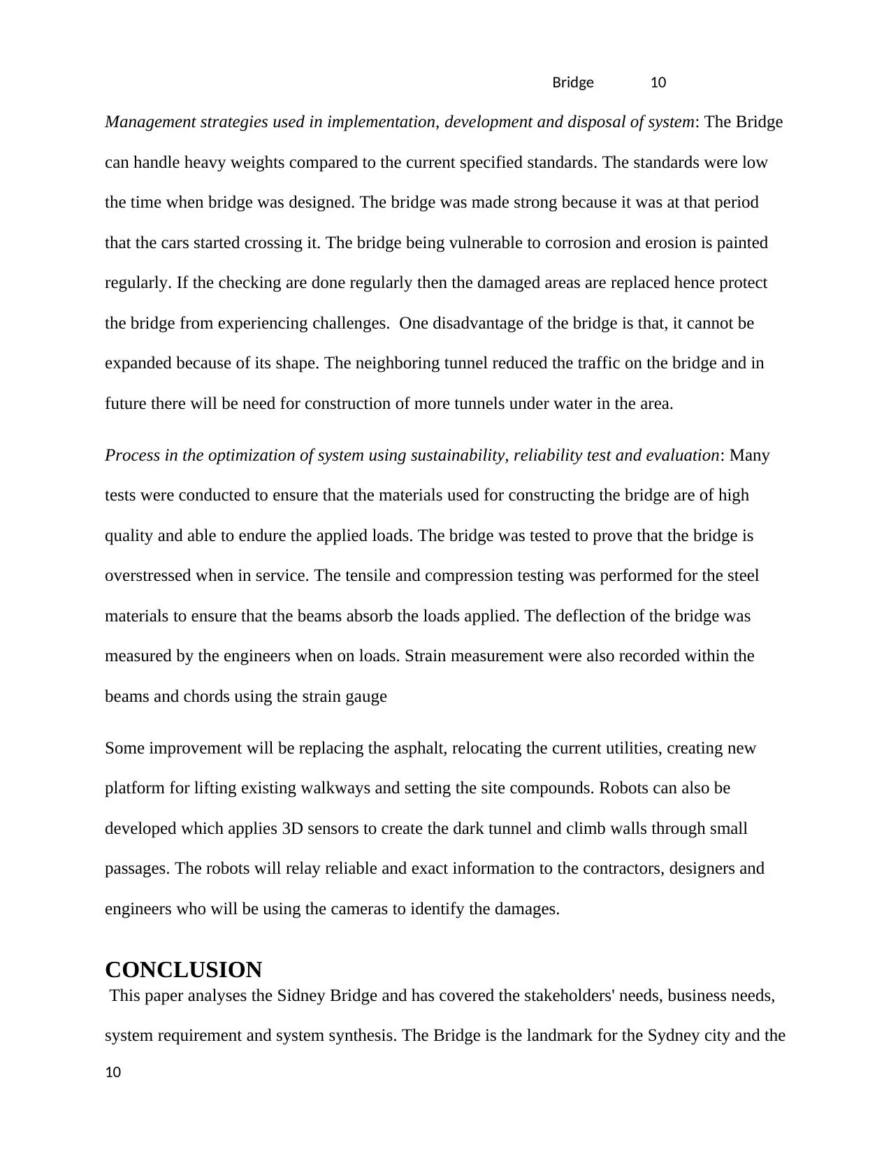
Management strategies used in implementation, development and disposal of system: The Bridge
can handle heavy weights compared to the current specified standards. The standards were low
the time when bridge was designed. The bridge was made strong because it was at that period
that the cars started crossing it. The bridge being vulnerable to corrosion and erosion is painted
regularly. If the checking are done regularly then the damaged areas are replaced hence protect
the bridge from experiencing challenges. One disadvantage of the bridge is that, it cannot be
expanded because of its shape. The neighboring tunnel reduced the traffic on the bridge and in
future there will be need for construction of more tunnels under water in the area.
Process in the optimization of system using sustainability, reliability test and evaluation: Many
tests were conducted to ensure that the materials used for constructing the bridge are of high
quality and able to endure the applied loads. The bridge was tested to prove that the bridge is
overstressed when in service. The tensile and compression testing was performed for the steel
materials to ensure that the beams absorb the loads applied. The deflection of the bridge was
measured by the engineers when on loads. Strain measurement were also recorded within the
beams and chords using the strain gauge
Some improvement will be replacing the asphalt, relocating the current utilities, creating new
platform for lifting existing walkways and setting the site compounds. Robots can also be
developed which applies 3D sensors to create the dark tunnel and climb walls through small
passages. The robots will relay reliable and exact information to the contractors, designers and
engineers who will be using the cameras to identify the damages.
CONCLUSION
This paper analyses the Sidney Bridge and has covered the stakeholders' needs, business needs,
system requirement and system synthesis. The Bridge is the landmark for the Sydney city and the
10
Paraphrase This Document
Need a fresh take? Get an instant paraphrase of this document with our AI Paraphraser
Bridge 11
citizens cannot accept any aesthetical change. The structure is stable and there is no need for
further reinforcement since its structures are still stable. This bridge link the Sydney CBD and
the north shore across the harbour. The southern part of the bridge is situated at Dawes Point in
the rock areas and the northern point is at in the lower north shores..
REFERENCES
Avşar, Ö., 2011. A Conceptual Design of a Cable Stayed Bridge with a Curved Back Span. Advanced
Materials Research, Volume 255-260, pp. 993-997.
Birch, G., 2017. Assessment of human-induced change and biological risk posed by contaminants in
estuarine/harbour sediments: Sydney Harbour/estuary (Australia). Marine Pollution Bulletin, Volume
116, pp. 234-248.
Gapps, S., 2011. Cockatoo Island, Sydney, Australia. Sydney Harbour Federation Trust. Martin Terry,
curator.. The Public Historian, Volume 33, pp. 145-152.
Harbour, J. L., 2011. The three “Ds“ of successful performance measurement: Design, data, and display.
Performance Improvement, Volume 50, pp. 5-12.
11
Bridge 12
Noël, M., 2011. Evaluation of FRP Posttensioned Slab Bridge Strips Using AASHTO-LRFD Bridge Design
Specifications. Journal of Bridge Engineering, Volume 16, pp. 839-846.
Och, D., 2018. Sydney Metro - ground characterisation and TBM selection for the Sydney Harbour
crossing. Geomechanics and Tunnelling, Volume 11, pp. 24-33.
O'Keeffe, A., 2014. The State of the Art of Bridge Information Modelling from Conceptual Design through
to Operation. International Journal of 3-D Information Modeling, Volume 3, pp. 29-39.
Park, P., 2011. Improved Geometric Design of Bridge Asphalt Plug Joints. Journal of Bridge Engineering,
Volume 16, pp. 158-165.
Roberts, L. A., 2011. Performance-Based Design of Drilled Shaft Bridge Foundations. Journal of Bridge
Engineering, Volume 16, pp. 749-758.
Sennah, K., 2015. Development and study of deck joints in prefabricated concrete bulb-tee bridge
girders: Conceptual design. Bridge Structures, Volume 11, pp. 33-53.
Tugilimana, A., 2017. Conceptual Design of Modular Bridges Including Layout Optimization and
Component Reusability. Journal of Bridge Engineering, Volume 22, p. 04017094.
12
⊘ This is a preview!⊘
Do you want full access?
Subscribe today to unlock all pages.
Trusted by 1+ million students worldwide
1 out of 12
Related Documents

Your All-in-One AI-Powered Toolkit for Academic Success.
+13062052269
info@desklib.com
Available 24*7 on WhatsApp / Email
![[object Object]](/_next/static/media/star-bottom.7253800d.svg)
Unlock your academic potential
Copyright © 2020–2026 A2Z Services. All Rights Reserved. Developed and managed by ZUCOL.