Stadium Design: Mechanical and Electrical Engineering Assessment
VerifiedAdded on 2023/06/10
|26
|2389
|55
Project
AI Summary
This project focuses on the mechanical and electrical design aspects of a football stadium for the Qatar 2022 World Cup, detailing the selection of appropriate materials and electrical components for long-term stability and safety. It covers the concept design phases, including pre-concept design, concept design, schematic design, and calculation development, leading to a construction start date. The project emphasizes the importance of choosing the right concrete, discussing various types, their properties, and destructive/non-destructive testing methods. It also addresses the electrical power requirements, proposing a renewable energy system with solar panels and energy-efficient LED lighting. Furthermore, the project includes circuit analysis using superposition and Thevenin's theorems and calculations for an RLC circuit, concluding with the selection of suitable materials and electrical components based on research and analysis.
ENGINEERING SCIENCE PART 2
Name of the Student
Name of the University
Author Note
Name of the Student
Name of the University
Author Note
Paraphrase This Document
Need a fresh take? Get an instant paraphrase of this document with our AI Paraphraser
Introduction:
The objective of this assignment is to build a football stadium for the Qatar 2022 world cup the
mechanical and electrical assessment of materials that are needed to be used are described in details
and the calculations of the strength and quantity of materials and electrical components are done that
will ensure stability for long time and safety of people inside the stadium. The constructional
components of the stadium such as the various load bearing materials, the types of concrete that can
be used are hypothesized and the breaking points of those are represented to select the most suitable
and safe items for the construction.
Concept Design of Stadium:
• Pre-concept design: Collecting data from different sources to do the analysis of the chosen site and the
confirmation of the requirements.
• Concept design: Developing the details of the design for determining the required construction materials and the
extra structures that are needed.
• Schematic design: The design of the whole stadium including major structures, gates and electrical components
using a software like AutoCAD or else.
• Calculation and development: Calculating the mechanical and electrical specifications of the different structures
and components and then choosing the best fitted equipment for the design.
• Date issue: Issuing a date for starting the real construction of the stadium. Selection of well experienced tender
before date of issue is recommended to ensure no delay in the date of issue.
⊘ This is a preview!⊘
Do you want full access?
Subscribe today to unlock all pages.

Trusted by 1+ million students worldwide
Task 1a:
Now, to construct a stadium it may take from approximately 18 months to 3 years depending on the
size of stadium, climate condition and unexpected events while ongoing construction process. The
generalized way of starting the construction is to construct a seating bowl through site excavation that
can be of 50 feet deep or more. Then the masonry work is performed with manufacturing the
components and installing them in planned places. After the initial phase the lights are installed,
concession areas, restrooms, locker room, portable toilets are installed. As the football stadium is
prepared for the world cup, hence there should be enough green grass in the field for players’ comfort
and improved playing condition. Now, as natural grass requires suitable soil conditions to grow which
may not available in chosen site, installing artificial grass can solve the problem at a lower cost and
minimized injury of players.
Paraphrase This Document
Need a fresh take? Get an instant paraphrase of this document with our AI Paraphraser
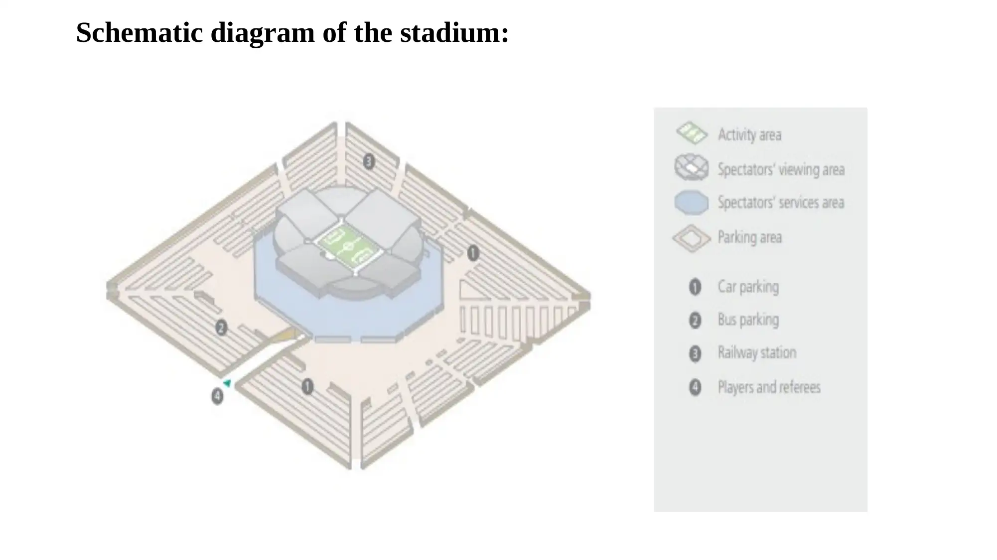
Schematic diagram of the stadium:
Construction Material:
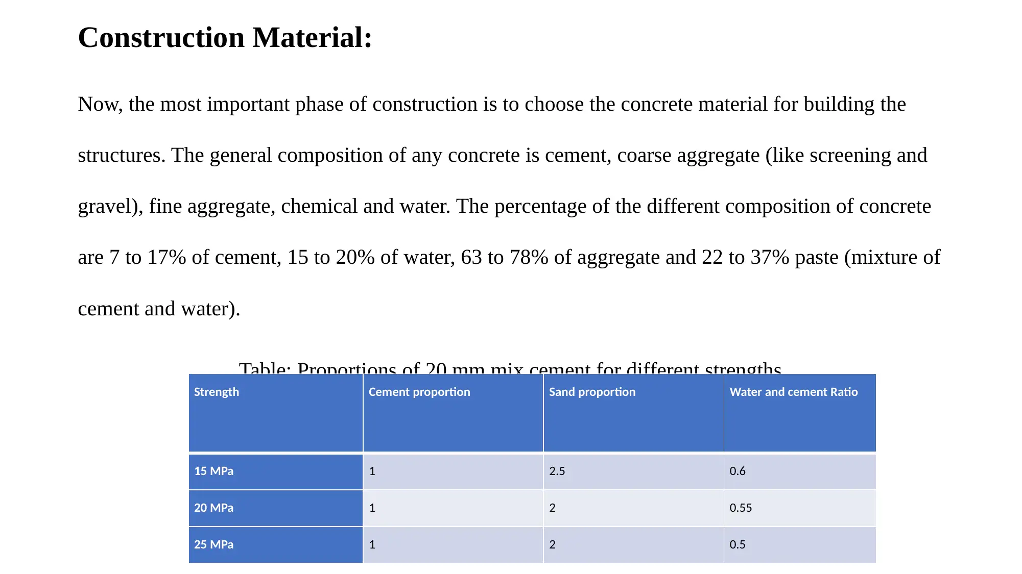
Now, the most important phase of construction is to choose the concrete material for building the
structures. The general composition of any concrete is cement, coarse aggregate (like screening and
gravel), fine aggregate, chemical and water. The percentage of the different composition of concrete
are 7 to 17% of cement, 15 to 20% of water, 63 to 78% of aggregate and 22 to 37% paste (mixture of
cement and water).
Table: Proportions of 20 mm mix cement for different strengths
Strength Cement proportion Sand proportion Water and cement Ratio
15 MPa 1 2.5 0.6
20 MPa 1 2 0.55
25 MPa 1 2 0.5
⊘ This is a preview!⊘
Do you want full access?
Subscribe today to unlock all pages.

Trusted by 1+ million students worldwide
Cement types:
The cement which is an essential component of the concrete can be of three types which are Portland
cement, blended cements, and colour cements. Now, Portland cements are used more generally to
form most of the structures (www-pub.iaea.org 2018). They can be of three types: High early
strength cement, Low heat cements and sulphate resisting cement. Now, as the stadium needs to be
completed early hence it is recommended to use the high early strength cements in most of the
position and in the guest seats and club house seats, low heat cements can be used to protect the seats
from heat during summer. Blended cements gain strength slowly and hence not recommended to use
in the stadium structures.
Paraphrase This Document
Need a fresh take? Get an instant paraphrase of this document with our AI Paraphraser
States of Concrete:
Now, addition of different chemicals with the cements make two stages of concretes which are
Plastic-state concrete and the hardened concrete. The two features of plastic-state concrete are
workability and cohesiveness. Workability of the plastic state concrete is high as this can be easily
handled while working and the cohesiveness of the concrete is the property which holds the
concrete after making the structure with it (www-pub.iaea.org 2018). The hardened concrete has
the two features durability and strength. It is highly durable as it can last long with no wear and tear
in extreme climate conditions and concrete at the hardened state has great strength. Increasing the
content cement and reducing the water content builds durability and strength and hence it is
recommended to use concretes with high amount of cement proportion.
Destructive and Non-destructive Methods:
Now, to judge the strength of the concrete and its breaking stress several Non-destructive and partial
destructive methods can be applied to get the quality of the concrete. The non-destructive quality tests are
slump test, compression tests (Gholizadeh 2016). The slump test tests the workability of the concrete while
the compression test judges the strength of the concrete in standardized condition (www-pub.iaea.org 2018).
The partial destructive tests that can be employed are Pull-out test, Pull-off test, Core test. The pull-out test
can be of two types 1) Danish Lok Test: A head is emerged into the concrete when it is in use. The test gives
a good indication of the compressive strength of the concrete. 2) BRE pull-out test: In this test a hole is
drilled inside the concrete structure and then a fixed object is pushed into it and then pulled out. This test
does not require the head to be casted in the structure of concrete, but it measures the tensile strength by
some calibration standard it is then converted into the compressive strength by some calibration standards.
⊘ This is a preview!⊘
Do you want full access?
Subscribe today to unlock all pages.

Trusted by 1+ million students worldwide
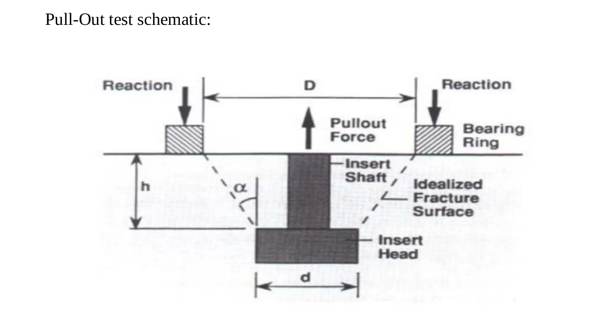
Pull-Out test schematic:
Paraphrase This Document
Need a fresh take? Get an instant paraphrase of this document with our AI Paraphraser
Flexure test:
In case of flexure test the theoretical maximum stress that can occur in the bottom fibre of the beam
which is known as modulus of rupture is calculated. In the calculation it is assumed that the stress is
directly proportional to the distance between the acing point and the neutral axis. Thus, the
estimation of the modulus of rupture will always be greater than the tensile strength and it depends
on the dimension of the beam.
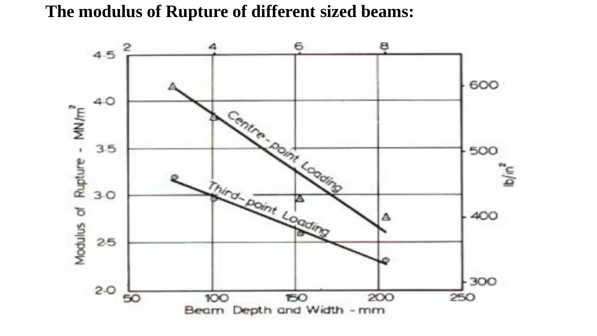
The modulus of Rupture of different sized beams:
⊘ This is a preview!⊘
Do you want full access?
Subscribe today to unlock all pages.

Trusted by 1+ million students worldwide
1 out of 26
Related Documents
Your All-in-One AI-Powered Toolkit for Academic Success.
+13062052269
info@desklib.com
Available 24*7 on WhatsApp / Email
![[object Object]](/_next/static/media/star-bottom.7253800d.svg)
Unlock your academic potential
Copyright © 2020–2025 A2Z Services. All Rights Reserved. Developed and managed by ZUCOL.


