Brunel University ME551 Building Management Control Systems Assignment
VerifiedAdded on 2023/06/03
|11
|2174
|414
Project
AI Summary
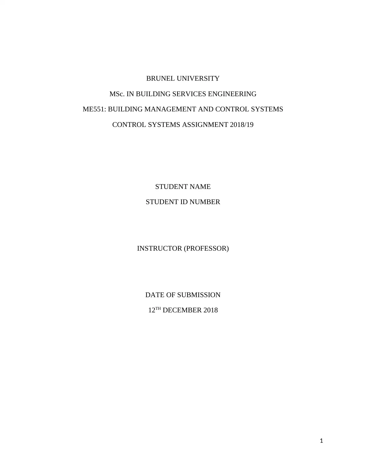
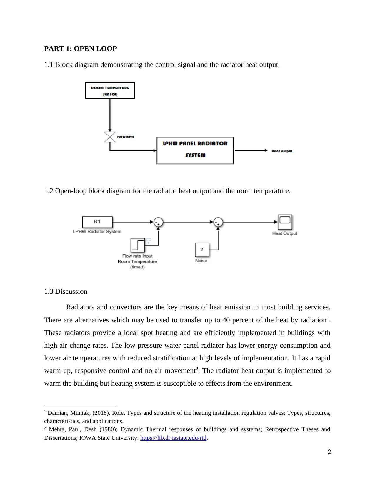
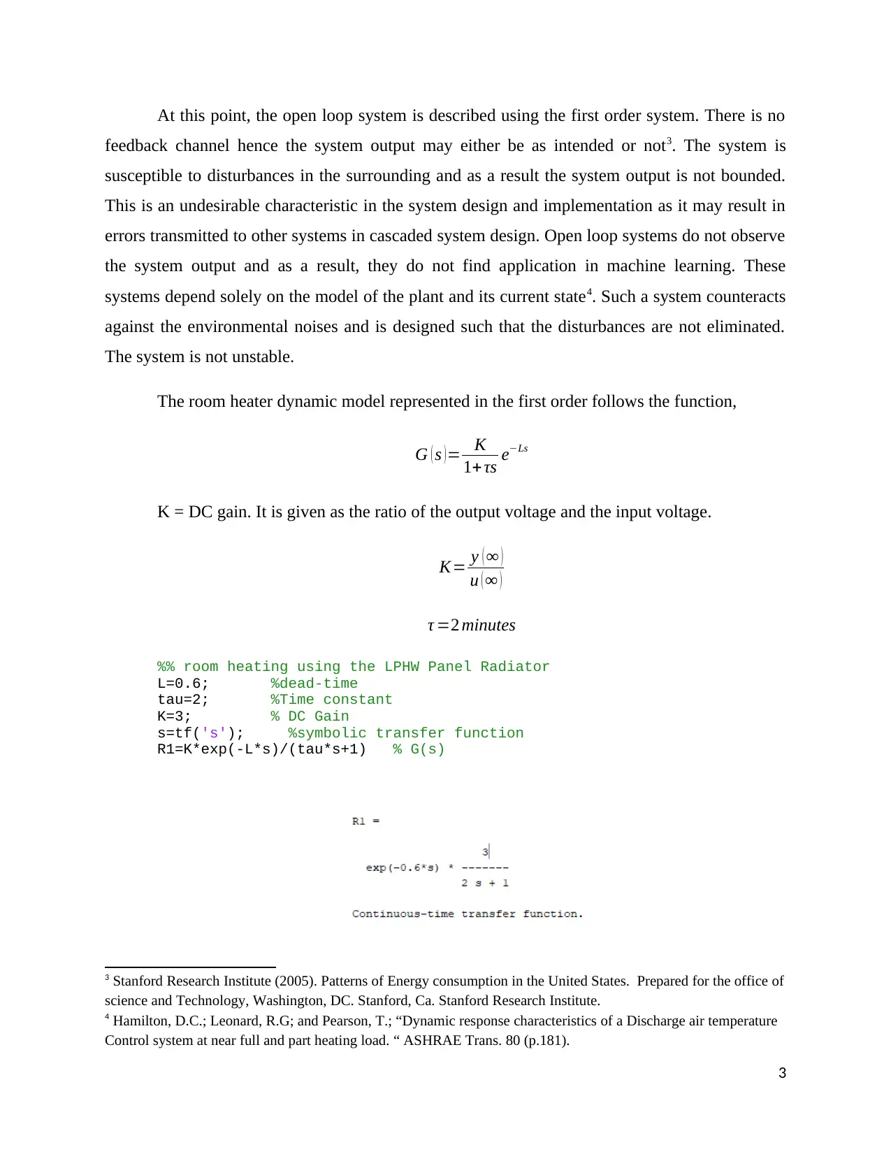
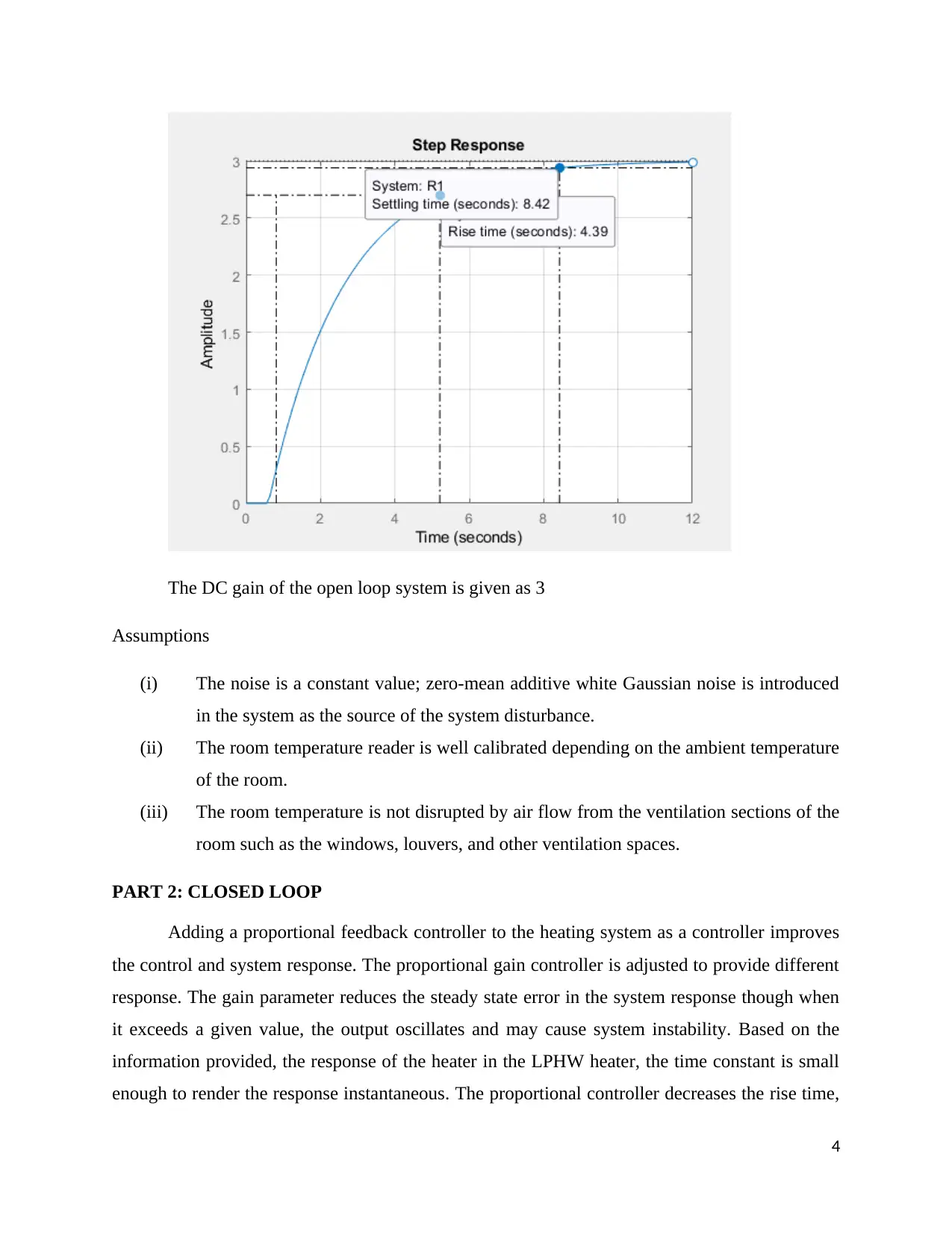
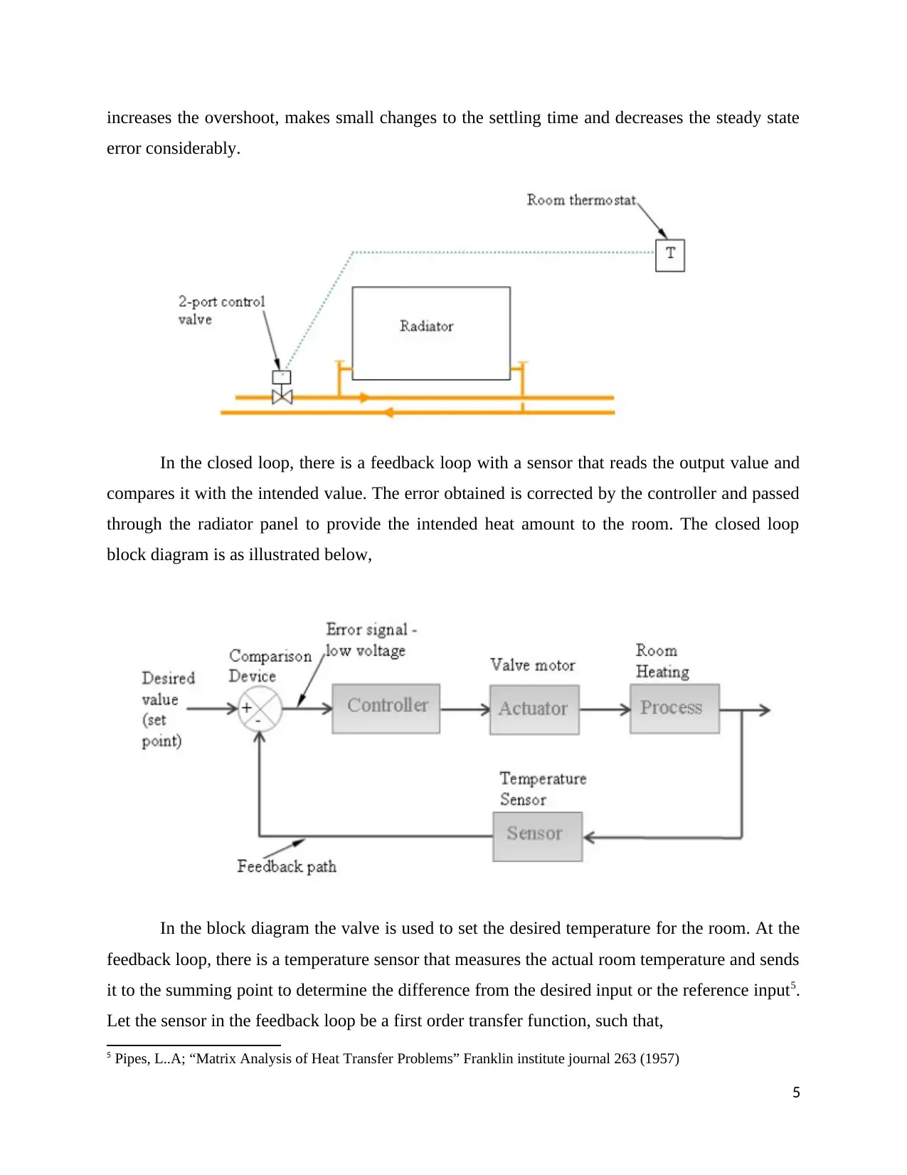
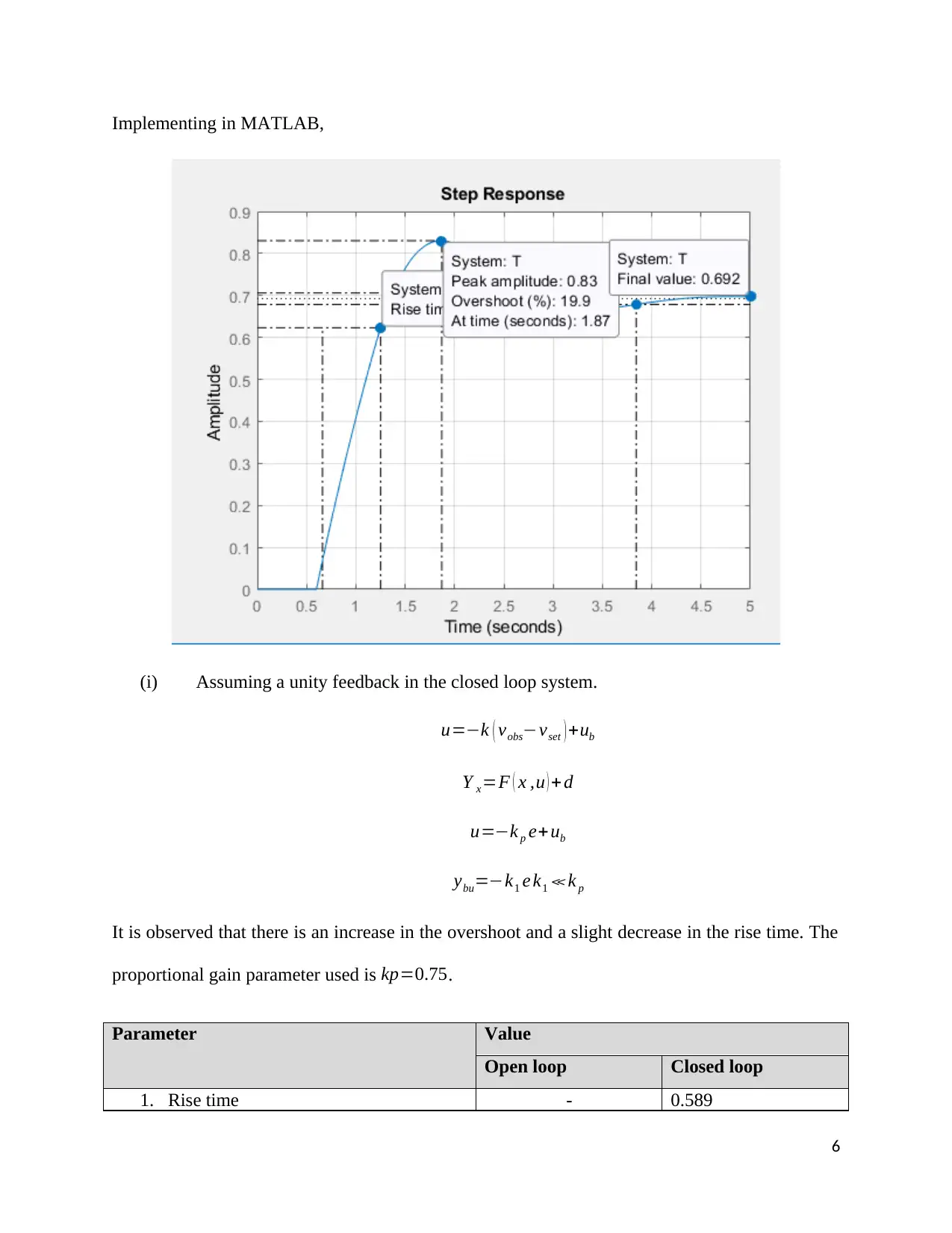
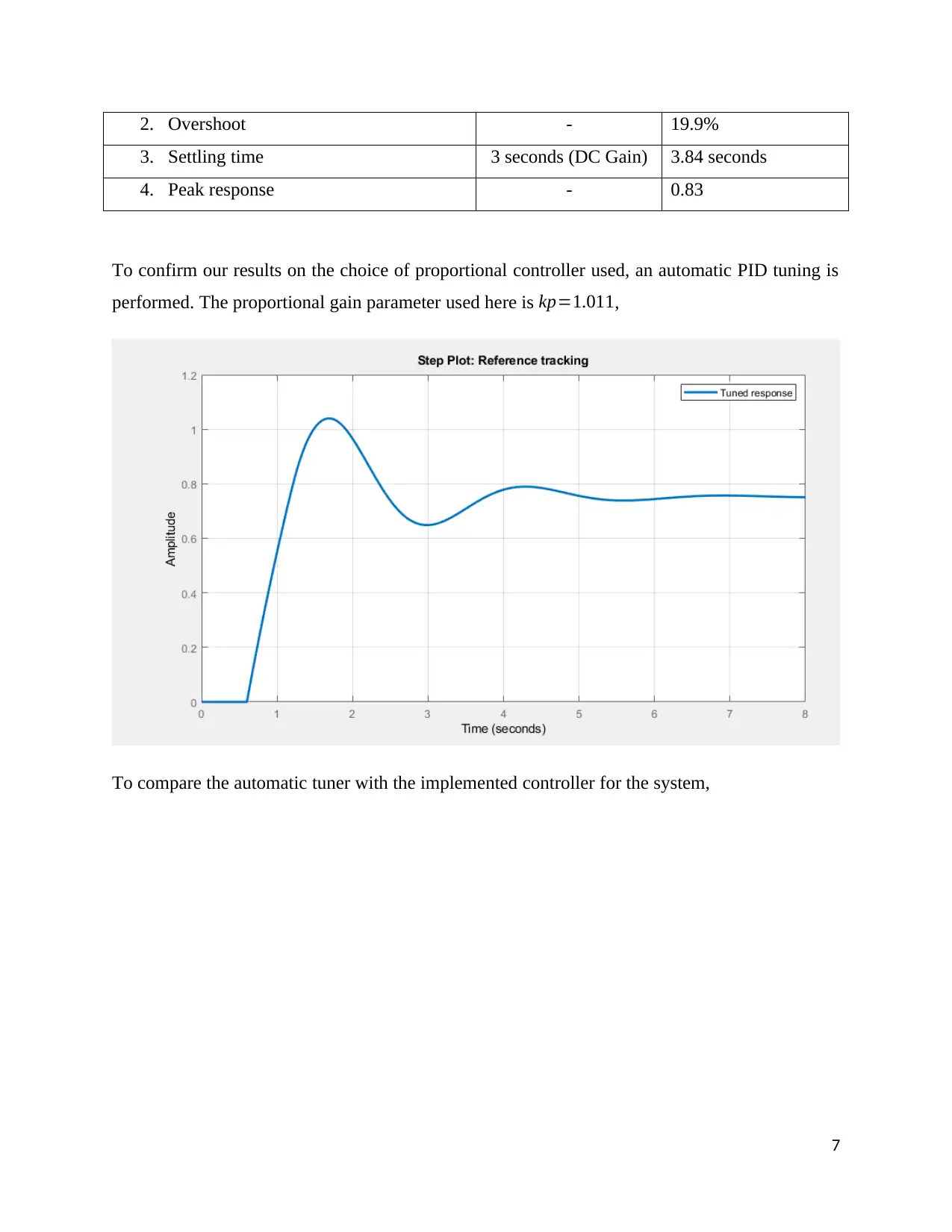
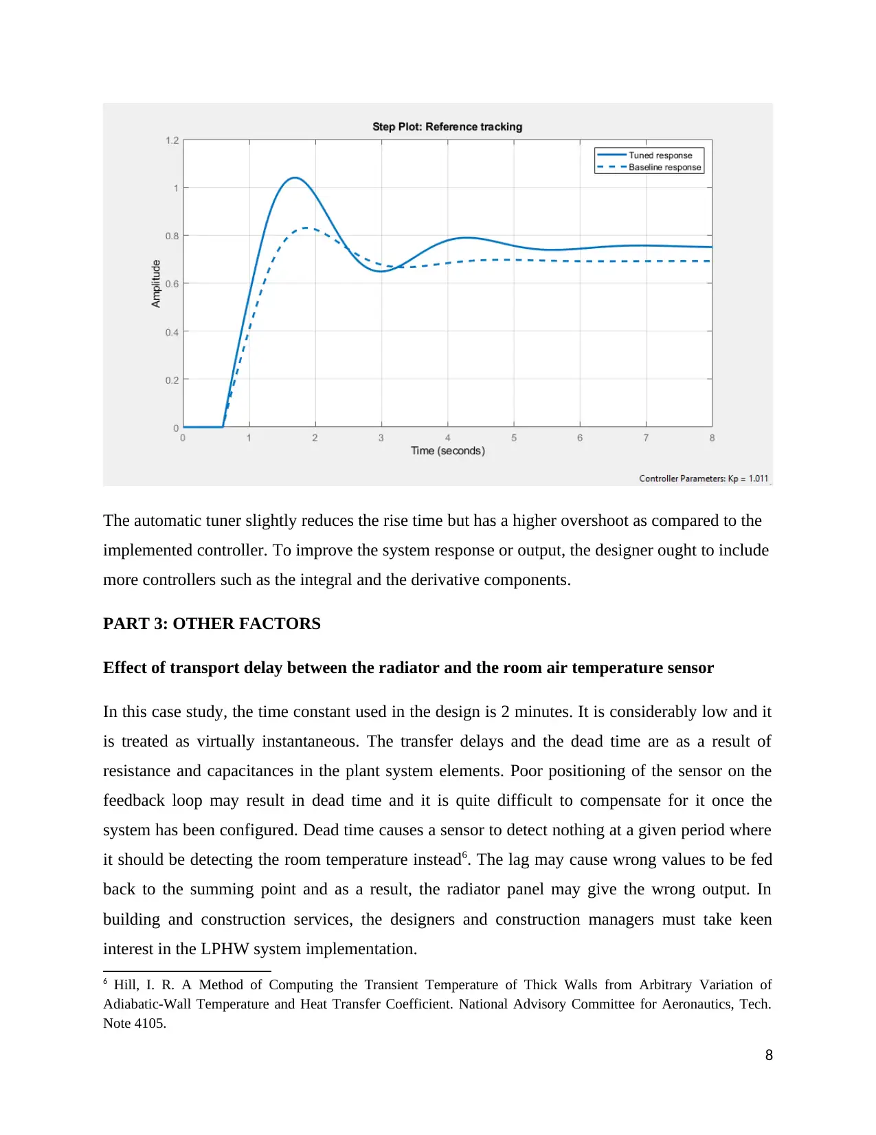
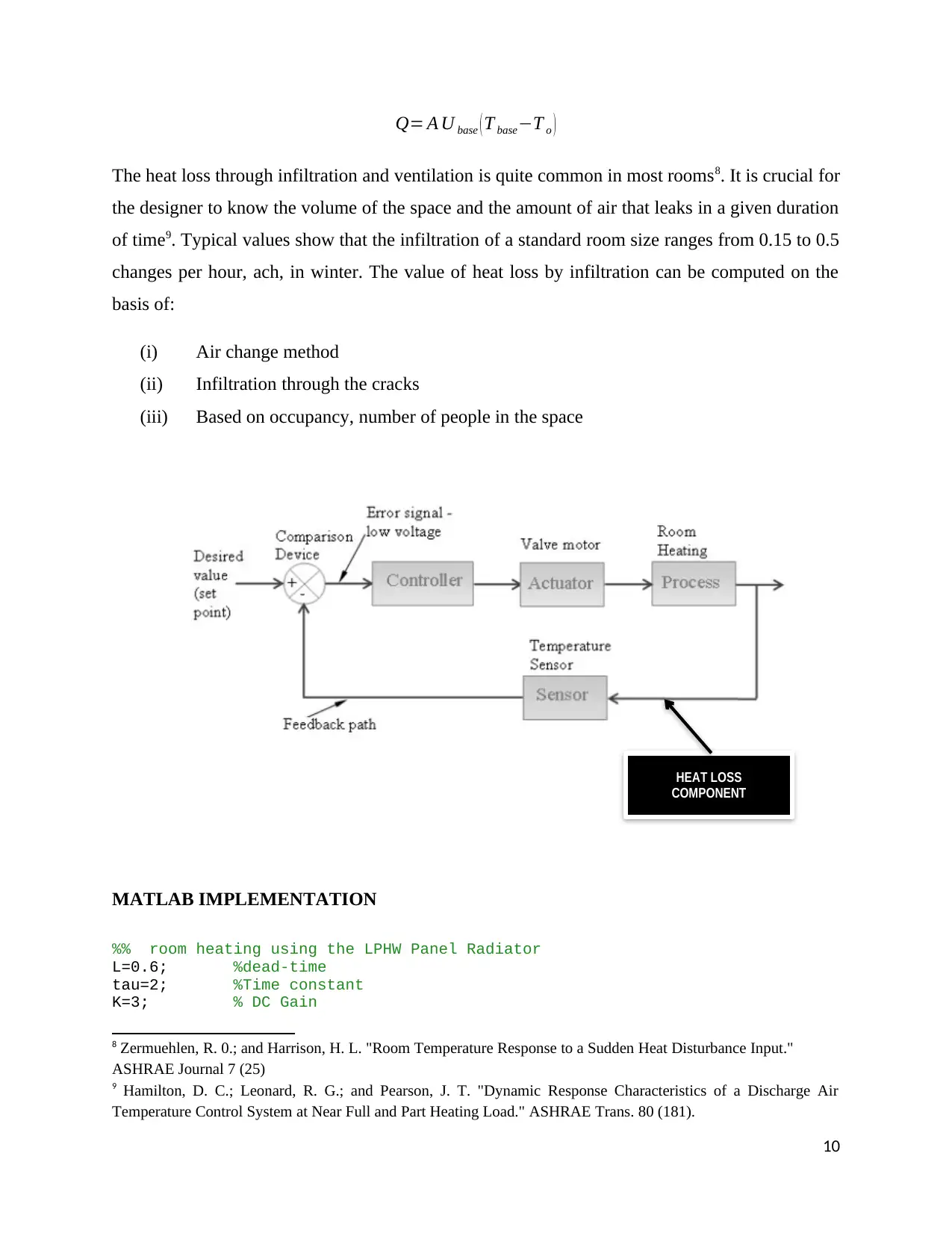
This assignment, for the MSc in Building Services Engineering module ME551 at Brunel University, focuses on the control of a room's heating system. It begins with an analysis of an open-loop system, modeling the radiator's heat output and its effect on room temperature using a first-order system, including a discussion of its limitations and susceptibility to disturbances. The assignment then proceeds to a closed-loop system, incorporating a proportional feedback controller to improve control and system response. MATLAB simulations are used to analyze the performance of the closed-loop system with and without automatic PID tuning, comparing the results and discussing the effects of the proportional gain parameter. Further, the assignment explores other factors like transport delay, sensor placement, and heat losses such as infiltration and ventilation. The solution also includes the implementation of these factors in MATLAB and discusses their effect on room temperature control. The conclusion summarizes the advantages of the closed-loop system and the importance of considering environmental factors for accurate temperature control.
1 out of 11


Your All-in-One AI-Powered Toolkit for Academic Success.
+13062052269
info@desklib.com
Available 24*7 on WhatsApp / Email
![[object Object]](/_next/static/media/star-bottom.7253800d.svg)
Copyright © 2020–2026 A2Z Services. All Rights Reserved. Developed and managed by ZUCOL.