Higher National Construction - Building Services Report: HVAC Systems
VerifiedAdded on 2020/04/13
|12
|2862
|141
Report
AI Summary
This report presents a comprehensive analysis of building services, focusing on the design of HVAC systems for a refurbishment project. It begins with an introduction to the project, which involves converting old Victorian buildings into flats. The report then delves into the legislative and technical compliance standards and requirements for HVAC systems, including boiler interlocks, zoning, heating controls, and pipe insulation. It provides a detailed comparison between traditional gas heating systems and new sustainable technologies such as solar thermal systems, evaluating their efficiency, environmental impact, and suitability. The report also covers electricity and fire control standards. Furthermore, it includes a practical application by calculating the winter heating load requirements for a specific flat within the building, considering factors like exterior and interior surface heat losses, infiltration, and ventilation. The report concludes with a summary of the key findings and recommendations for the HVAC system design. Appendices include detailed calculations and data used in the analysis.

Higher National Construction
Year 1 Level 4 Assessment
Module: Building Services Report
Module Number: AURH 446
Dated: 21st October 2017
1
Year 1 Level 4 Assessment
Module: Building Services Report
Module Number: AURH 446
Dated: 21st October 2017
1
Paraphrase This Document
Need a fresh take? Get an instant paraphrase of this document with our AI Paraphraser
Higher National Construction
Year 1 Level 4 Assessment
Introduction
Design of essential building services is often required to comply with the minimum standards
and requirements. In this report, a project on refurbishment of the existing building by
inclusion of the essential services is hereby pursued following a request by a client to offer
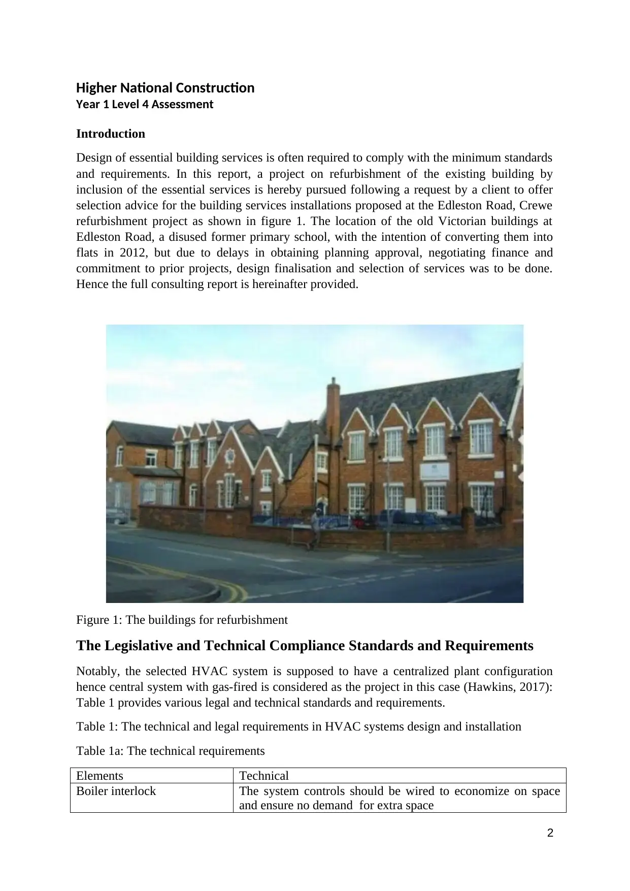
selection advice for the building services installations proposed at the Edleston Road, Crewe
refurbishment project as shown in figure 1. The location of the old Victorian buildings at
Edleston Road, a disused former primary school, with the intention of converting them into
flats in 2012, but due to delays in obtaining planning approval, negotiating finance and
commitment to prior projects, design finalisation and selection of services was to be done.
Hence the full consulting report is hereinafter provided.
Figure 1: The buildings for refurbishment
The Legislative and Technical Compliance Standards and Requirements
Notably, the selected HVAC system is supposed to have a centralized plant configuration
hence central system with gas-fired is considered as the project in this case (Hawkins, 2017):
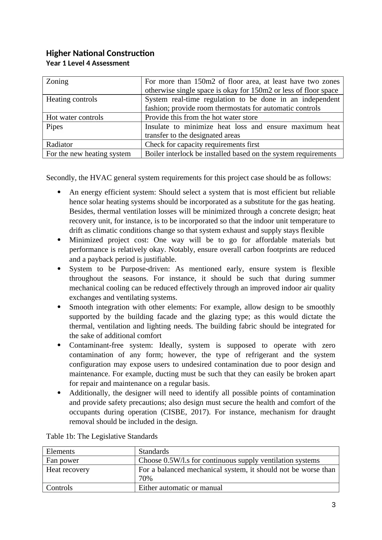
Table 1 provides various legal and technical standards and requirements.
Table 1: The technical and legal requirements in HVAC systems design and installation
Table 1a: The technical requirements
Elements Technical
Boiler interlock The system controls should be wired to economize on space
and ensure no demand for extra space
2
Higher National Construction
Year 1 Level 4 Assessment
Zoning For more than 150m2 of floor area, at least have two zones
otherwise single space is okay for 150m2 or less of floor space
Heating controls System real-time regulation to be done in an independent
fashion; provide room thermostats for automatic controls
Hot water controls Provide this from the hot water store
Pipes Insulate to minimize heat loss and ensure maximum heat
transfer to the designated areas
Radiator Check for capacity requirements first
For the new heating system Boiler interlock be installed based on the system requirements
Secondly, the HVAC general system requirements for this project case should be as follows:
An energy efficient system: Should select a system that is most efficient but reliable
hence solar heating systems should be incorporated as a substitute for the gas heating.
Besides, thermal ventilation losses will be minimized through a concrete design; heat
recovery unit, for instance, is to be incorporated so that the indoor unit temperature to
drift as climatic conditions change so that system exhaust and supply stays flexible
Minimized project cost: One way will be to go for affordable materials but
performance is relatively okay. Notably, ensure overall carbon footprints are reduced
and a payback period is justifiable.
System to be Purpose-driven: As mentioned early, ensure system is flexible
throughout the seasons. For instance, it should be such that during summer
mechanical cooling can be reduced effectively through an improved indoor air quality
exchanges and ventilating systems.
Smooth integration with other elements: For example, allow design to be smoothly
supported by the building facade and the glazing type; as this would dictate the
thermal, ventilation and lighting needs. The building fabric should be integrated for
the sake of additional comfort
Contaminant-free system: Ideally, system is supposed to operate with zero
contamination of any form; however, the type of refrigerant and the system
configuration may expose users to undesired contamination due to poor design and
maintenance. For example, ducting must be such that they can easily be broken apart
for repair and maintenance on a regular basis.
Additionally, the designer will need to identify all possible points of contamination
and provide safety precautions; also design must secure the health and comfort of the
occupants during operation (CISBE, 2017). For instance, mechanism for draught
removal should be included in the design.
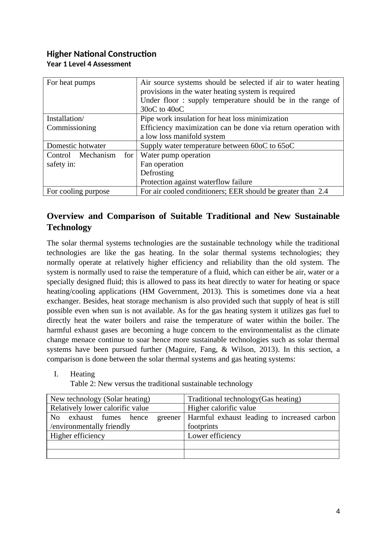
Table 1b: The Legislative Standards
Elements Standards
Fan power Choose 0.5W/l.s for continuous supply ventilation systems
Heat recovery For a balanced mechanical system, it should not be worse than
70%
Controls Either automatic or manual
3
⊘ This is a preview!⊘
Do you want full access?
Subscribe today to unlock all pages.

Trusted by 1+ million students worldwide
Higher National Construction
Year 1 Level 4 Assessment
For heat pumps Air source systems should be selected if air to water heating
provisions in the water heating system is required
Under floor : supply temperature should be in the range of
30oC to 40oC
Installation/
Commissioning
Pipe work insulation for heat loss minimization
Efficiency maximization can be done via return operation with
a low loss manifold system
Domestic hotwater Supply water temperature between 60oC to 65oC
Control Mechanism for
safety in:
Water pump operation
Fan operation
Defrosting
Protection against waterflow failure
For cooling purpose For air cooled conditioners; EER should be greater than 2.4
Overview and Comparison of Suitable Traditional and New Sustainable
Technology
The solar thermal systems technologies are the sustainable technology while the traditional
technologies are like the gas heating. In the solar thermal systems technologies; they
normally operate at relatively higher efficiency and reliability than the old system. The
system is normally used to raise the temperature of a fluid, which can either be air, water or a
specially designed fluid; this is allowed to pass its heat directly to water for heating or space
heating/cooling applications (HM Government, 2013). This is sometimes done via a heat
exchanger. Besides, heat storage mechanism is also provided such that supply of heat is still
possible even when sun is not available. As for the gas heating system it utilizes gas fuel to
directly heat the water boilers and raise the temperature of water within the boiler. The
harmful exhaust gases are becoming a huge concern to the environmentalist as the climate
change menace continue to soar hence more sustainable technologies such as solar thermal
systems have been pursued further (Maguire, Fang, & Wilson, 2013). In this section, a
comparison is done between the solar thermal systems and gas heating systems:
I. Heating
Table 2: New versus the traditional sustainable technology
New technology (Solar heating) Traditional technology(Gas heating)
Relatively lower calorific value Higher calorific value
No exhaust fumes hence greener
/environmentally friendly
Harmful exhaust leading to increased carbon
footprints
Higher efficiency Lower efficiency
4
Paraphrase This Document
Need a fresh take? Get an instant paraphrase of this document with our AI Paraphraser
Higher National Construction
Year 1 Level 4 Assessment
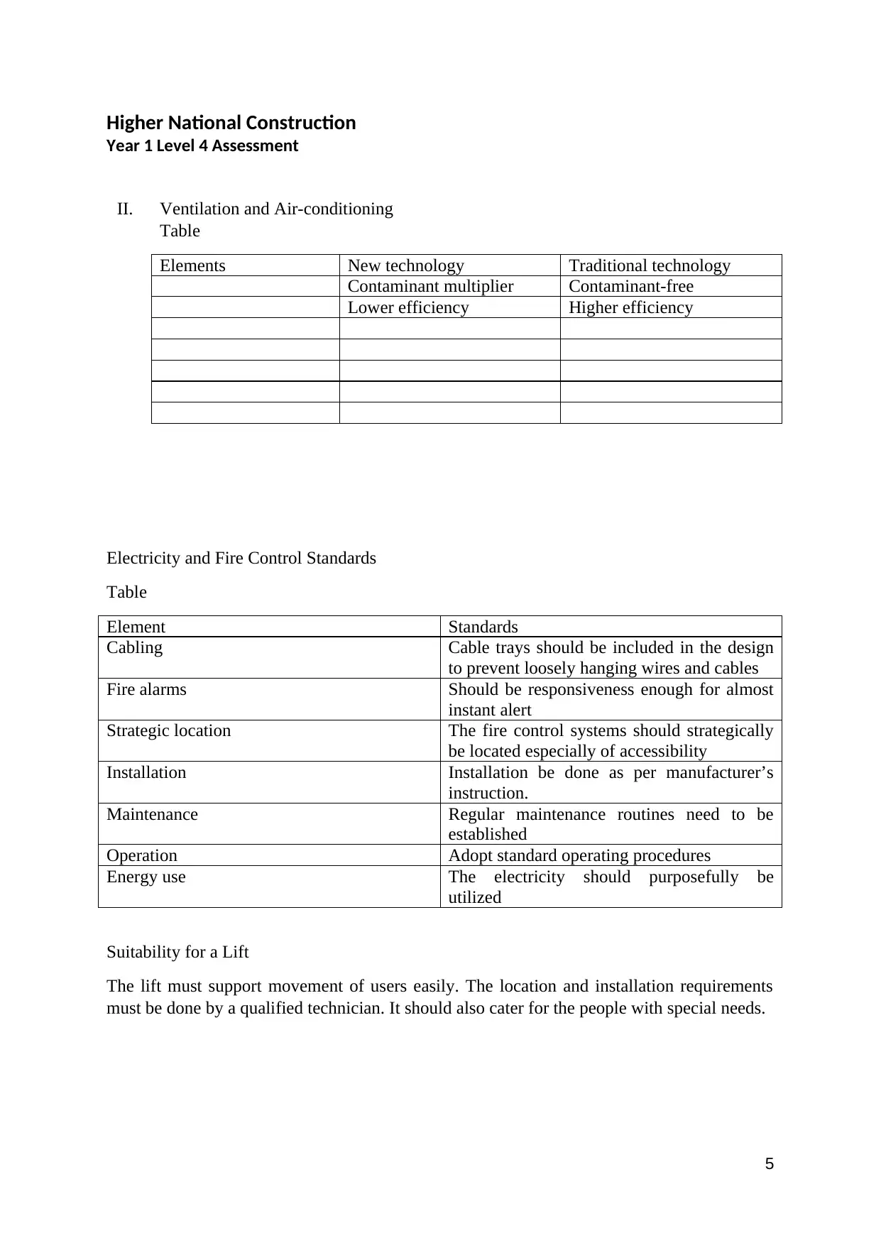
II. Ventilation and Air-conditioning
Table
Elements New technology Traditional technology
Contaminant multiplier Contaminant-free
Lower efficiency Higher efficiency
Electricity and Fire Control Standards
Table
Element Standards
Cabling Cable trays should be included in the design
to prevent loosely hanging wires and cables
Fire alarms Should be responsiveness enough for almost
instant alert
Strategic location The fire control systems should strategically
be located especially of accessibility
Installation Installation be done as per manufacturer’s
instruction.
Maintenance Regular maintenance routines need to be
established
Operation Adopt standard operating procedures
Energy use The electricity should purposefully be
utilized
Suitability for a Lift
The lift must support movement of users easily. The location and installation requirements
must be done by a qualified technician. It should also cater for the people with special needs.
5
Higher National Construction
Year 1 Level 4 Assessment
Conclusion
The report has dwelt on the standards and requirements both legal and technical that are
relevant in the given project case. A number of issues are to be complied with in the design,
installation and operation of the HVAC system.
APPENDICES
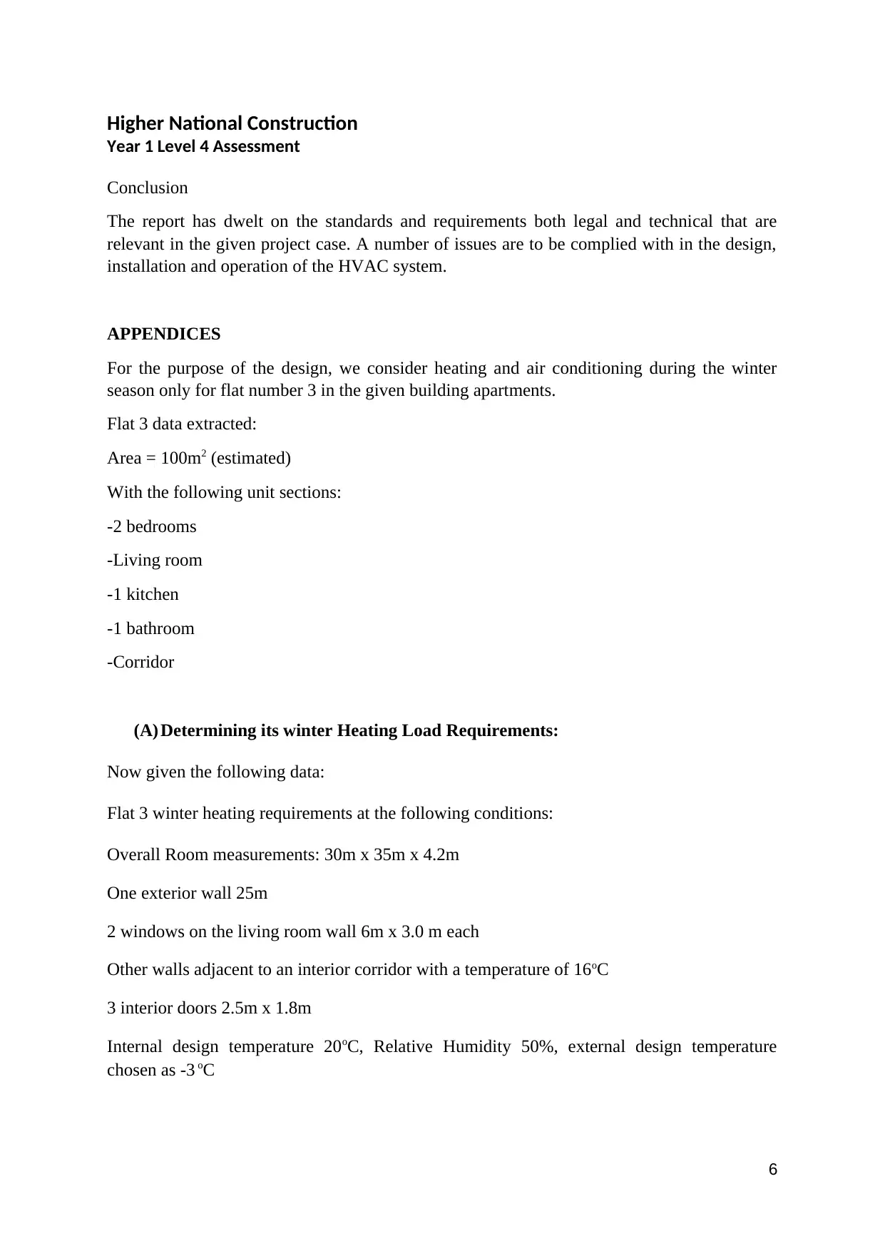
For the purpose of the design, we consider heating and air conditioning during the winter
season only for flat number 3 in the given building apartments.
Flat 3 data extracted:
Area = 100m2 (estimated)
With the following unit sections:
-2 bedrooms
-Living room
-1 kitchen
-1 bathroom
-Corridor
(A) Determining its winter Heating Load Requirements:
Now given the following data:
Flat 3 winter heating requirements at the following conditions:
Overall Room measurements: 30m x 35m x 4.2m
One exterior wall 25m
2 windows on the living room wall 6m x 3.0 m each
Other walls adjacent to an interior corridor with a temperature of 16oC
3 interior doors 2.5m x 1.8m
Internal design temperature 20oC, Relative Humidity 50%, external design temperature
chosen as -3 oC
6
⊘ This is a preview!⊘
Do you want full access?
Subscribe today to unlock all pages.

Trusted by 1+ million students worldwide
Higher National Construction
Year 1 Level 4 Assessment
Each person is allowed to occupy about 1.75m2
So:
No. of persons in the flat= 30× 35
17.5 =60 persons
Winter loads differ from those calculated for summer loads. It is assumed that such systems
will have the maximum heat losses from the building. Secondly, heat is being lost from the
building since the outside temperature is lower that the interior design temperature. This
scenario suggests that, there is NO latent heat loads to be calculated, only sensible. Moreover,
to consider the worst scenario possible, the heating loads coming from people, appliances and
lighting are ignored. In fact these type of loads would only be considered as heat gains, which
in fact favours the load of the Heating system.
So the only calculations involved will be the heat losses through the fabric, ventilation and
infiltration. All the theory to calculate such loads is given below in this section.
The winter outer conditions are -3oC with a relative humidity of 100% and the design indoor
temperature should be 20oC with 50% relative humidity.
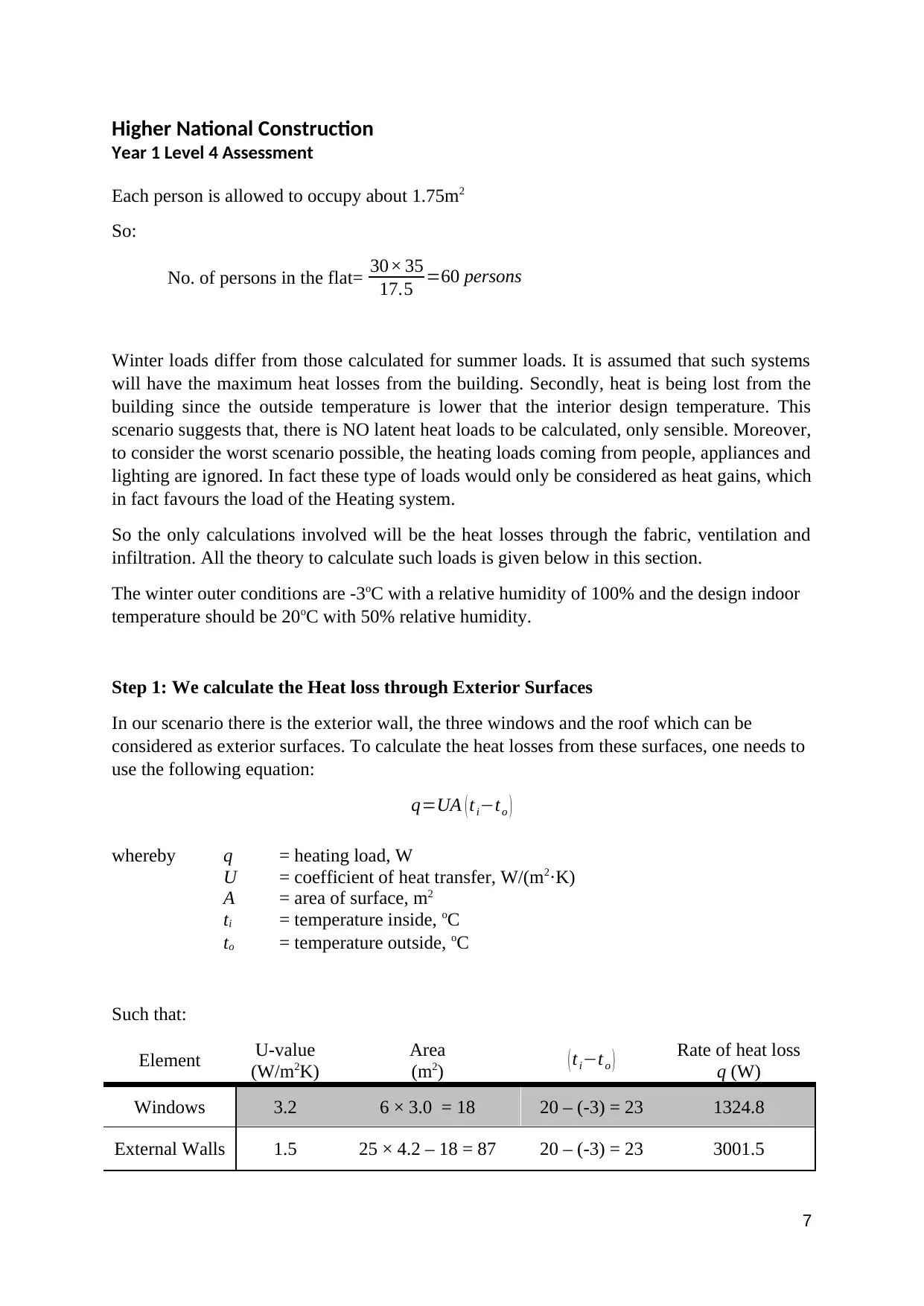
Step 1: We calculate the Heat loss through Exterior Surfaces
In our scenario there is the exterior wall, the three windows and the roof which can be
considered as exterior surfaces. To calculate the heat losses from these surfaces, one needs to
use the following equation:
q=UA ( ti−to )
whereby q = heating load, W
U = coefficient of heat transfer, W/(m2·K)
A = area of surface, m2
ti = temperature inside, oC
to = temperature outside, oC
Such that:
Element U-value
(W/m2K)
Area
(m2) ( ti−to ) Rate of heat loss
q (W)
Windows 3.2 6 × 3.0 = 18 20 – (-3) = 23 1324.8
External Walls 1.5 25 × 4.2 – 18 = 87 20 – (-3) = 23 3001.5
7
Paraphrase This Document
Need a fresh take? Get an instant paraphrase of this document with our AI Paraphraser
Higher National Construction
Year 1 Level 4 Assessment
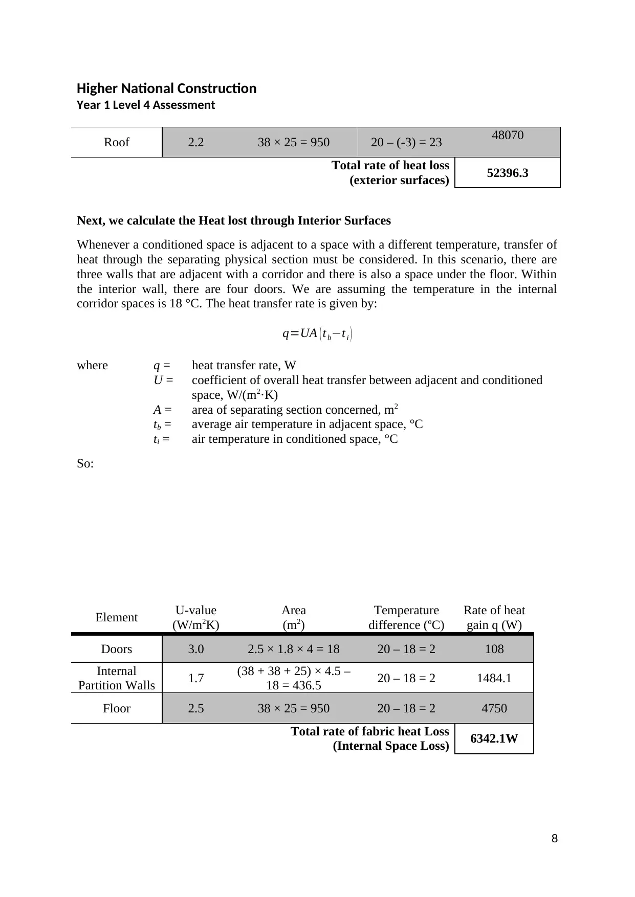
Roof 2.2 38 × 25 = 950 20 – (-3) = 23 48070
Total rate of heat loss
(exterior surfaces) 52396.3
Next, we calculate the Heat lost through Interior Surfaces
Whenever a conditioned space is adjacent to a space with a different temperature, transfer of
heat through the separating physical section must be considered. In this scenario, there are
three walls that are adjacent with a corridor and there is also a space under the floor. Within
the interior wall, there are four doors. We are assuming the temperature in the internal
corridor spaces is 18 °C. The heat transfer rate is given by:
q=UA ( tb−ti )
where q = heat transfer rate, W
U = coefficient of overall heat transfer between adjacent and conditioned
space, W/(m2·K)
A = area of separating section concerned, m2
tb = average air temperature in adjacent space, °C
ti = air temperature in conditioned space, °C
So:
Element U-value
(W/m2K)
Area
(m2)
Temperature
difference (oC)
Rate of heat
gain q (W)
Doors 3.0 2.5 × 1.8 × 4 = 18 20 – 18 = 2 108
Internal
Partition Walls 1.7 (38 + 38 + 25) × 4.5 –
18 = 436.5 20 – 18 = 2 1484.1
Floor 2.5 38 × 25 = 950 20 – 18 = 2 4750
Total rate of fabric heat Loss
(Internal Space Loss) 6342.1W
8
Higher National Construction
Year 1 Level 4 Assessment
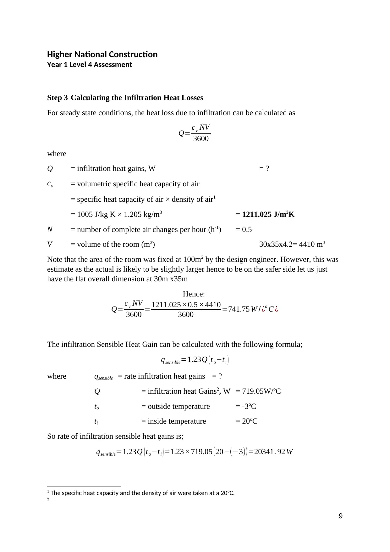
Step 3 Calculating the Infiltration Heat Losses
For steady state conditions, the heat loss due to infiltration can be calculated as
Q= cv NV
3600
where
Q = infiltration heat gains, W = ?
cv = volumetric specific heat capacity of air
= specific heat capacity of air × density of air1
= 1005 J/kg K × 1.205 kg/m3 = 1211.025 J/m3K
N = number of complete air changes per hour (h-1) = 0.5
V = volume of the room (m3) 30x35x4.2= 4410 m3
Note that the area of the room was fixed at 100m2 by the design engineer. However, this was
estimate as the actual is likely to be slightly larger hence to be on the safer side let us just
have the flat overall dimension at 30m x35m
Hence:
Q= cv NV
3600 = 1211.025 ×0.5 × 4410
3600 =741.75 W /¿o C ¿
The infiltration Sensible Heat Gain can be calculated with the following formula;
qsensible=1.23Q ( t o−t i )
where qsensible = rate infiltration heat gains = ?
Q = infiltration heat Gains2, W = 719.05W/oC
to = outside temperature = -3oC
ti = inside temperature = 20oC
So rate of infiltration sensible heat gains is;
qsensible=1.23Q ( to−ti )=1.23 ×719.05 ( 20−(−3) ) =20341. 92 W
1 The specific heat capacity and the density of air were taken at a 20oC.
2
9
⊘ This is a preview!⊘
Do you want full access?
Subscribe today to unlock all pages.

Trusted by 1+ million students worldwide
Higher National Construction
Year 1 Level 4 Assessment
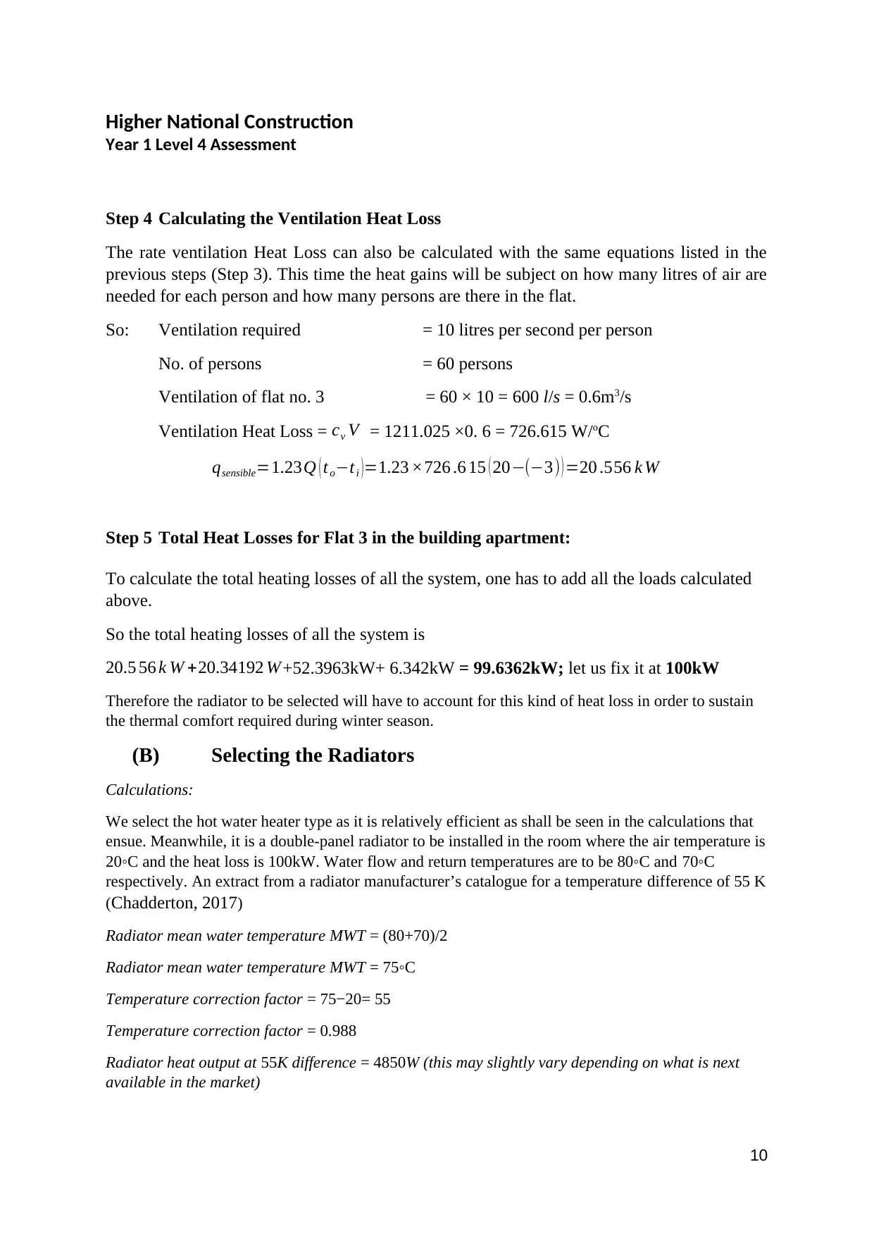
Step 4 Calculating the Ventilation Heat Loss
The rate ventilation Heat Loss can also be calculated with the same equations listed in the
previous steps (Step 3). This time the heat gains will be subject on how many litres of air are
needed for each person and how many persons are there in the flat.
So: Ventilation required = 10 litres per second per person
No. of persons = 60 persons
Ventilation of flat no. 3 = 60 × 10 = 600 l/s = 0.6m3/s
Ventilation Heat Loss = cv V = 1211.025 ×0. 6 = 726.615 W/oC
qsensible=1.23Q ( to−ti )=1.23 ×726 .6 15 ( 20−(−3) ) =20 .556 k W
Step 5 Total Heat Losses for Flat 3 in the building apartment:
To calculate the total heating losses of all the system, one has to add all the loads calculated
above.
So the total heating losses of all the system is
20.5 56 k W +20.34192 W+52.3963kW+ 6.342kW = 99.6362kW; let us fix it at 100kW
Therefore the radiator to be selected will have to account for this kind of heat loss in order to sustain
the thermal comfort required during winter season.
(B) Selecting the Radiators
Calculations:
We select the hot water heater type as it is relatively efficient as shall be seen in the calculations that
ensue. Meanwhile, it is a double-panel radiator to be installed in the room where the air temperature is
20◦C and the heat loss is 100kW. Water flow and return temperatures are to be 80◦C and 70◦C
respectively. An extract from a radiator manufacturer’s catalogue for a temperature difference of 55 K
(Chadderton, 2017)
Radiator mean water temperature MWT = (80+70)/2
Radiator mean water temperature MWT = 75◦C
Temperature correction factor = 75−20= 55
Temperature correction factor = 0.988
Radiator heat output at 55K difference = 4850W (this may slightly vary depending on what is next
available in the market)
10
Paraphrase This Document
Need a fresh take? Get an instant paraphrase of this document with our AI Paraphraser
Higher National Construction
Year 1 Level 4 Assessment
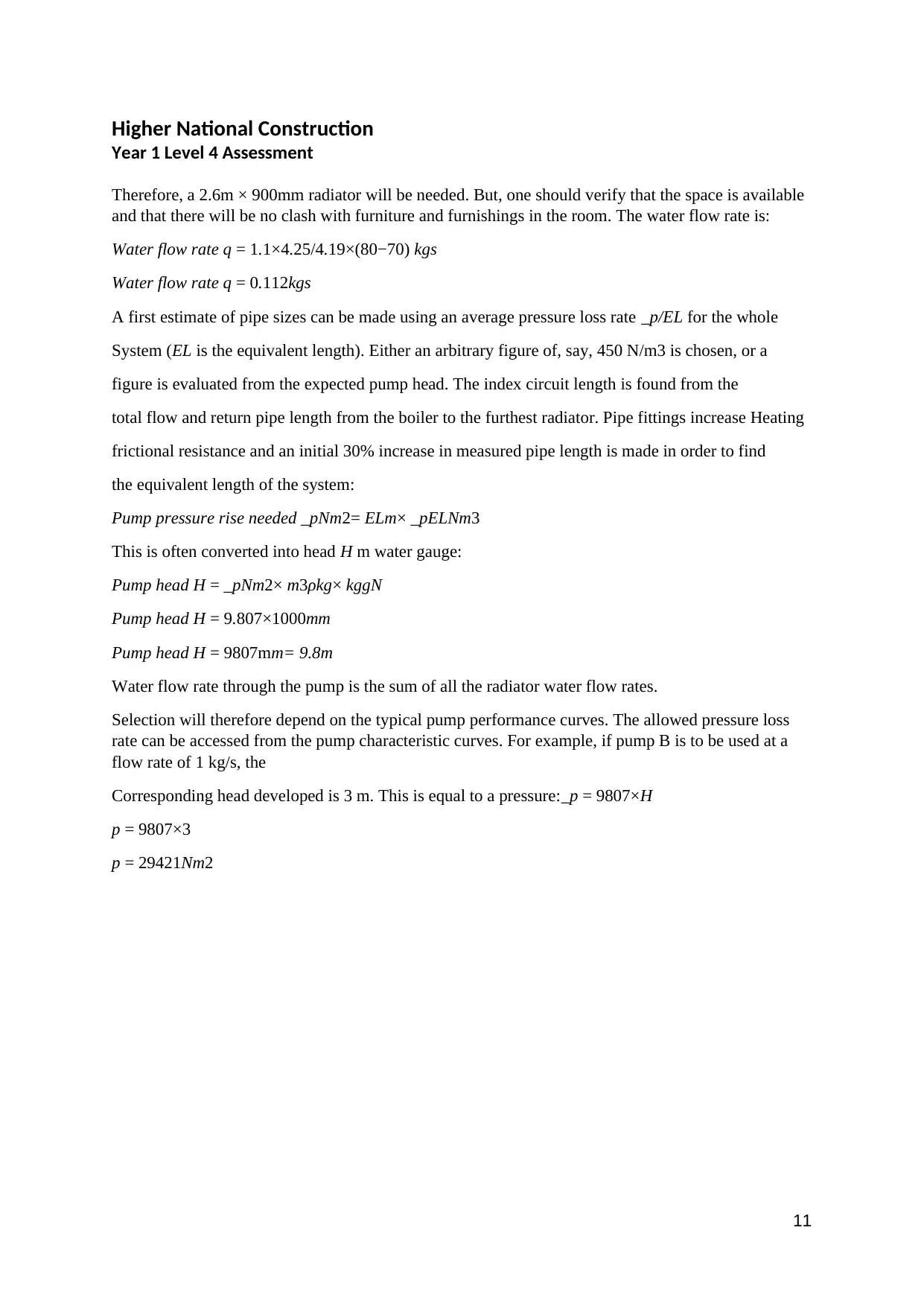
Therefore, a 2.6m × 900mm radiator will be needed. But, one should verify that the space is available
and that there will be no clash with furniture and furnishings in the room. The water flow rate is:
Water flow rate q = 1.1×4.25/4.19×(80−70) kgs
Water flow rate q = 0.112kgs
A first estimate of pipe sizes can be made using an average pressure loss rate _p/EL for the whole
System (EL is the equivalent length). Either an arbitrary figure of, say, 450 N/m3 is chosen, or a
figure is evaluated from the expected pump head. The index circuit length is found from the
total flow and return pipe length from the boiler to the furthest radiator. Pipe fittings increase Heating
frictional resistance and an initial 30% increase in measured pipe length is made in order to find
the equivalent length of the system:
Pump pressure rise needed _pNm2= ELm× _pELNm3
This is often converted into head H m water gauge:
Pump head H = _pNm2× m3ρkg× kggN
Pump head H = 9.807×1000mm
Pump head H = 9807mm= 9.8m
Water flow rate through the pump is the sum of all the radiator water flow rates.
Selection will therefore depend on the typical pump performance curves. The allowed pressure loss
rate can be accessed from the pump characteristic curves. For example, if pump B is to be used at a
flow rate of 1 kg/s, the
Corresponding head developed is 3 m. This is equal to a pressure:_p = 9807×H
p = 9807×3
p = 29421Nm2
11
Higher National Construction
Year 1 Level 4 Assessment
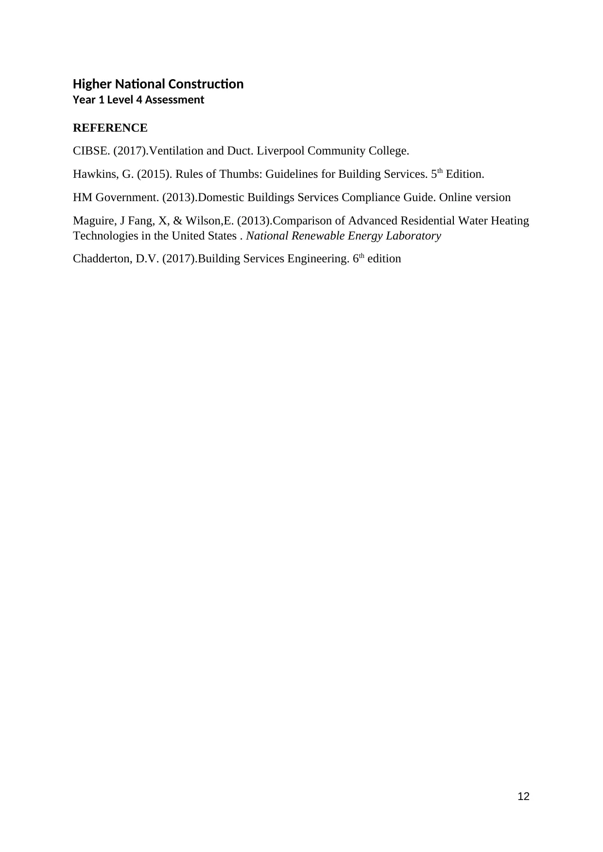
REFERENCE
CIBSE. (2017).Ventilation and Duct. Liverpool Community College.
Hawkins, G. (2015). Rules of Thumbs: Guidelines for Building Services. 5th Edition.
HM Government. (2013).Domestic Buildings Services Compliance Guide. Online version
Maguire, J Fang, X, & Wilson,E. (2013).Comparison of Advanced Residential Water Heating
Technologies in the United States . National Renewable Energy Laboratory
Chadderton, D.V. (2017).Building Services Engineering. 6th edition
12
⊘ This is a preview!⊘
Do you want full access?
Subscribe today to unlock all pages.

Trusted by 1+ million students worldwide
1 out of 12
Related Documents
Your All-in-One AI-Powered Toolkit for Academic Success.
+13062052269
info@desklib.com
Available 24*7 on WhatsApp / Email
![[object Object]](/_next/static/media/star-bottom.7253800d.svg)
Unlock your academic potential
Copyright © 2020–2025 A2Z Services. All Rights Reserved. Developed and managed by ZUCOL.


