Designing Cantilever and Retaining Wall Structures Assignment
VerifiedAdded on 2023/06/11
|11
|1228
|107
Report
AI Summary
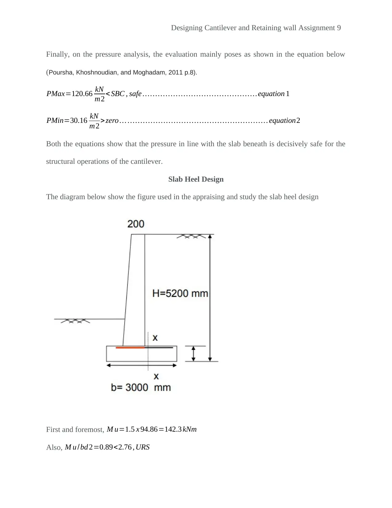
This assignment provides a detailed solution for the design of cantilever and retaining walls. It includes foundation design, wall proportioning, stem design with shear checking and analysis, and stability checks. The design adheres to relevant standards, incorporating calculations for overturning, sliding, and subsidence. The pressure analysis confirms the safety of the slab beneath the cantilever. The assignment also covers slab heel design, ensuring structural integrity. References to relevant publications are included. Desklib is a platform where students can find similar solved assignments and past papers.

1 out of 11
Your All-in-One AI-Powered Toolkit for Academic Success.
+13062052269
info@desklib.com
Available 24*7 on WhatsApp / Email
![[object Object]](/_next/static/media/star-bottom.7253800d.svg)
Copyright © 2020–2025 A2Z Services. All Rights Reserved. Developed and managed by ZUCOL.