logo

Hydraulic and Pneumatic Circuit Analysis


Added on  2020-04-13

5 Pages981 Words64 Views
 | 
 | 
 | 
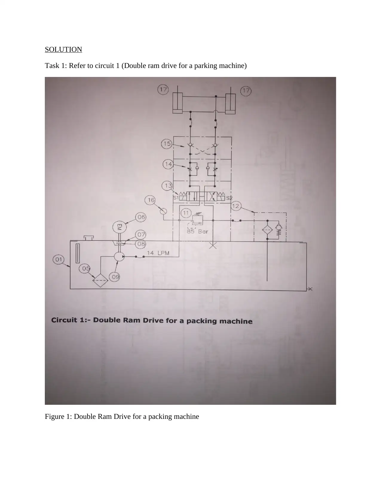
SOLUTIONTask 1: Refer to circuit 1 (Double ram drive for a parking machine)Figure 1: Double Ram Drive for a packing machine
Hydraulic and Pneumatic Circuit Analysis_1

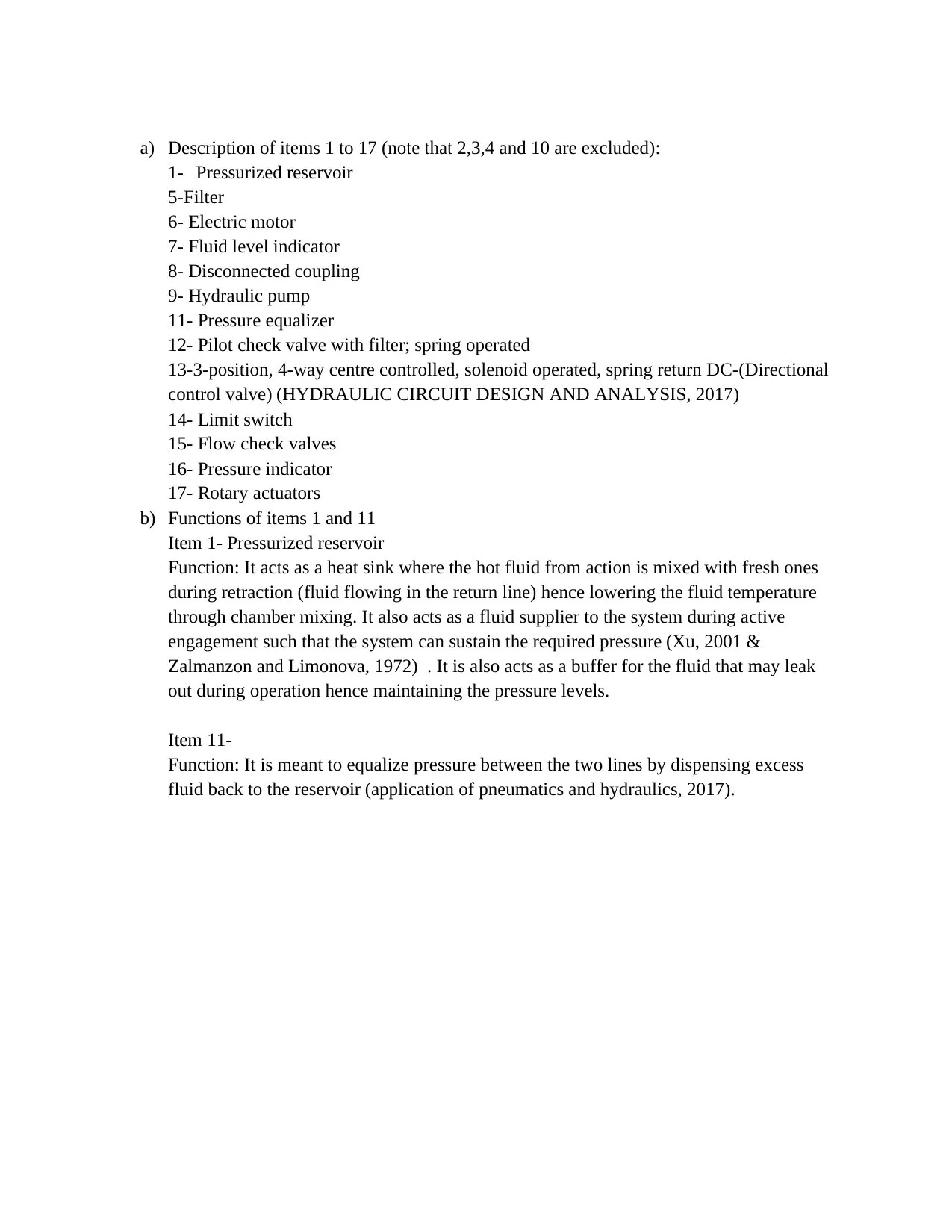
a)Description of items 1 to 17 (note that 2,3,4 and 10 are excluded): 1-Pressurized reservoir 5-Filter6- Electric motor 7- Fluid level indicator 8- Disconnected coupling9- Hydraulic pump11- Pressure equalizer 12- Pilot check valve with filter; spring operated13-3-position, 4-way centre controlled, solenoid operated, spring return DC-(Directional control valve)(HYDRAULIC CIRCUIT DESIGN AND ANALYSIS, 2017)14- Limit switch 15- Flow check valves 16- Pressure indicator 17- Rotary actuatorsb)Functions of items 1 and 11Item 1- Pressurized reservoir Function: It acts as a heat sink where the hot fluid from action is mixed with fresh ones during retraction (fluid flowing in the return line) hence lowering the fluid temperature through chamber mixing. It also acts as a fluid supplier to the system during active engagement such that the system can sustain the required pressure(Xu, 2001 &Zalmanzon and Limonova, 1972) . It is also acts as a buffer for the fluid that may leak out during operation hence maintaining the pressure levels. Item 11-Function: It is meant to equalize pressure between the two lines by dispensing excess fluid back to the reservoir(application of pneumatics and hydraulics, 2017).
Hydraulic and Pneumatic Circuit Analysis_2

End of preview

Want to access all the pages? Upload your documents or become a member.

Related Documents