ME 508 - Analysis and Design of Oil Storage Tank Safety System
VerifiedAdded on 2022/11/23
|7
|1711
|246
Project
AI Summary
This document presents a comprehensive analysis of a safety shutdown system for an oil storage tank, focusing on the prevention of crude oil leakage. The solution details the oversight modes of level sensors, control valves, and the Basic Process Control System (BPCS). It includes a failure analysis, categorizing failures based on severity and component type, and emphasizes the importance of interlocks. The document also features a reliability block diagram, fault tree analysis, and the determination of the target Safety Integrity Level (SIL) for a new Safety Instrumented Function (SIF). Furthermore, it explores risk graphs and Layer of Protection Analysis (LOPA) for risk reduction and safety enhancement. The second part of the document addresses the safety aspects of rotating spindles, including machine-related hazards, safety control functions, and the determination of Performance Level and SIL. The analysis is supported by references to industry standards and relevant publications.
CASE 1: SAFETY SHUTDOWN SYSTEM FOR OIL STORAGE TANK
The safety control system is used in the case of oil storage tanks for safe shutdown and
prevention of leakage of crude oil. The basic requirement for a control system is for
regulation and maintenance of the required flow rate and pressure of oil in the tank.
SOLUTIONS
a) Oversight modes of level sensor, control valve, BPCS and associated process.
The safety instrumented system (SIS) is developed to satisfy and comply the sets of rules
prescribed by the nation. These requirements sometimes get ignored and disaster occurs. To
determine the failures, all the equipment’s must be considered and evaluated by making a list
of all the failure modes and their effects. The failure modes should be selected as level of
severeness, low level, high level and medium level. The threats of failure which are so small
or negligible should be neglected and work must be followed on. There can be three types of
failure of the component; upside, downside and in position. The Level Control Valve (LCV-
001), Regulatory Control Loop (LIC-001) or Level Sensor and the basic control system could
face these three failures in context to their arrangements. Fails for LCV-001 if fully open
valve; upside fall controller output decelerate to zero, if fully closed valve; output rises to
maximum or if fails in position; output goes completely open if set variable is varied. In
Level Sensors failures could be either upside if valve is completely closed or downsides if
valve is completely open. All the failures of LCV-001 and LIC-001 are single variable
failure. To safeguard, controllers need to be precisely interlocked. [1]
Level sensors performance required by management is to reduce the near misses incidents, to
strike off the possibility of casualties due to hazardous liquid leakage or overflow. Level
sensors should encounter the difference between similarity and proximity. According to
MinHash algorithm, proximity is:
[Pa-b = {(Ka
∩Kb) ÷ (Ka∪Kb)}]
where, Pa-b is proximity of events a and b;
Ka and Kb are sorted sentences, respectively in the events a and b sorted by search engine.[2]
BPCS (Basic process control system) uses layer of protection analysis (LOPA) for huge
pitfall situations. Various systems and levels of protection are used according to the situation.
IEC 61511 Edition 2 (2016); the new standards set by the process industries. The standard
Paraphrase This Document
Need a fresh take? Get an instant paraphrase of this document with our AI Paraphraser
analysing process for the risk reduction factor; more than 10000, LOPA is used with other
SIS to analyse the hazards. For example in hydrocracker reactor inside petroleum refineries
an uncontrolled exothermic reaction can cause severe casualties in lined with the exposure of
flammable hydrocarbons and hydrogen gas. The implementation of instrumented control
systems using BPCS protects the system from vulnerability. Concluding these analyses a
robust design of safeguard technology is achieved for requisite performance requirements. [3]
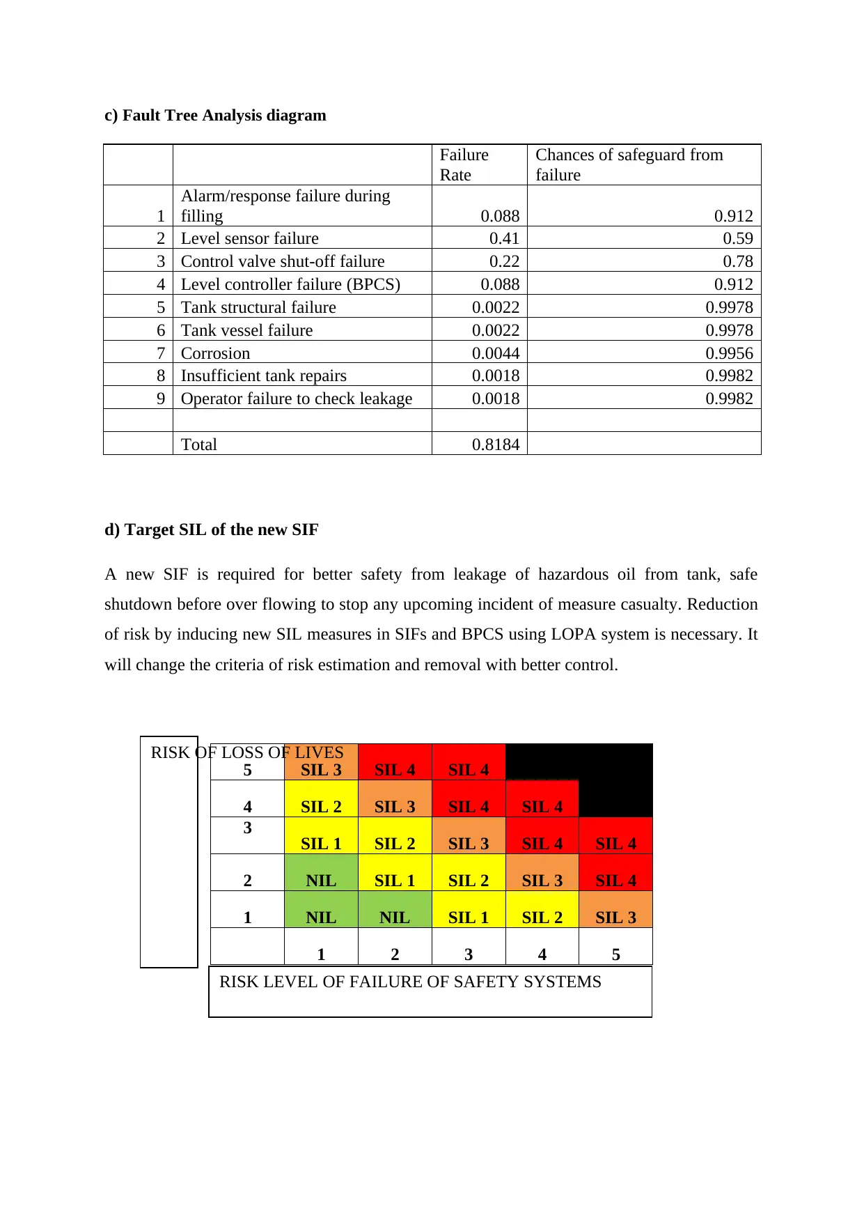
b) Reliability Block Diagram
c) Fault Tree Analysis diagram
Failure
Rate
Chances of safeguard from
failure
1
Alarm/response failure during
filling 0.088 0.912
2 Level sensor failure 0.41 0.59
3 Control valve shut-off failure 0.22 0.78
4 Level controller failure (BPCS) 0.088 0.912
5 Tank structural failure 0.0022 0.9978
6 Tank vessel failure 0.0022 0.9978
7 Corrosion 0.0044 0.9956
8 Insufficient tank repairs 0.0018 0.9982
9 Operator failure to check leakage 0.0018 0.9982
Total 0.8184
d) Target SIL of the new SIF
A new SIF is required for better safety from leakage of hazardous oil from tank, safe
shutdown before over flowing to stop any upcoming incident of measure casualty. Reduction
of risk by inducing new SIL measures in SIFs and BPCS using LOPA system is necessary. It
will change the criteria of risk estimation and removal with better control.
5 SIL 3 SIL 4 SIL 4
4 SIL 2 SIL 3 SIL 4 SIL 4
3 SIL 1 SIL 2 SIL 3 SIL 4 SIL 4
2 NIL SIL 1 SIL 2 SIL 3 SIL 4
1 NIL NIL SIL 1 SIL 2 SIL 3
1 2 3 4 5
RISK OF LOSS OF LIVES
RISK LEVEL OF FAILURE OF SAFETY SYSTEMS
⊘ This is a preview!⊘
Do you want full access?
Subscribe today to unlock all pages.

Trusted by 1+ million students worldwide
e) Extent of Risk Graph and Implementation of LOPA
A risk graph is a method of demonstrating large number of data, all failure or risks
identifications measures and the level of the threats are appropriately demonstrated on a
single page. Although there are mainly two ways to determine, plan and execute the risk
removal factors from the system, risk graph and Layer Protection Analysis (LOPA) for SIL.
Risk graphs have limitation, it can be not simulate any situation and analyse where as in layer
protection analysis new situation could also be framed and its simulation and analysis could
be done easily.[4] It can reduce the effective time for the risk analysis and widen the security
protection layer with minimal effort. Layer protection analysis also allows risk reduction
incorporated in SIL attributes with very huge level f precision. Risk graphs are used in less
complex structures, the safety required parameter is from low to medium. LOPA is widely
used in the much complex setups; oil refineries, hazardous chemical factories, nuclear power
plants, ordinance factories, etc.
Case 2: Safety from Rotating Spindle
a) Limits of machinery
Moving parts of machines are very dangerous to be in contact, safeguard from it is
mandatory. Rotating spindles rotate at very high speed, about 3000 rpm – 15000 rpm
sometimes exceeds to 30000 rpm. In this scenario, if the spindle looses its grip on the work
piece or any damaged piece gets struck off, will create a huge risk of loss of lives and
property. Even slow rotating motion can be dangerous in certain situations like a cloth of an
operator stuck in spindle, takes away life most of the time. In order to determine the limits for
safety while machine operations, sets of rules must be followed. All machine parts should be
checked thoroughly for loose connections and correct tools must be used to avoid any
undesirable reaction.
b) Machine related hazards
Possibilities of hazards while working near any machinery are dependent on machine and the
type of operation on going, exposing to loud noise, vibrations, gas leakage, heat, cold, dust,
radiation, etc.[5] As there are numerous possibilities of hazards that could lead to minor
Paraphrase This Document
Need a fresh take? Get an instant paraphrase of this document with our AI Paraphraser
accidents, disabilities or even cause death, an assessment should be done for all parameters of
error either human or machine.
c) Safety Related Control Function
Some of the functions like usage limits, space limits and time limits should be referred. In
usage limit; the use of machinery or its parts safety parameters are considered, space limits;
area in which the machinery is setup and minimum distance for safeguard of machine
operators while the time limit; the operation time or machine running time should be
monitored. The basic elements to be considered for implementation of safety systems are to
acknowledge the triggering events, safety related reaction and to check all the dangerous part
of the machine. In case of power failure, a safety system should ensure the stoppage of
movement of the machine parts that are dangerous. If any machine part is damaged and still
moving, creates danger to life and other machining processes.
d) Performance Level and SIL
The SIL codes for SRCF, according to the different parameters like, the time of exposure to
the machine under faulty condition, probability of occurrence of hazardous activities, etc.
According to the IEC 62061:2005, governs the functional safety of machine for electrical,
electronics and control systems.[6] For robotic systems, parts for safety control in control
system should be designed keeping in mind the codes as, PL=d with format pattern 3 as
illustrated in ISO 13849-1:2006 otherwise should comply SIL 2 with disintegration level 2
with success examination of 20 years and above as elaborated under IEC 62061:2005.
REFERENCES
[1]"When can the process control system, safety system share field devices?", Control
Engineering, 2019. [Online]. Available: https://www.controleng.com/articles/when-can-the-
process-control-system-safety-system-share-field-devices/. [Accessed: 17- Sep- 2019].
[2]S. M. Ansaldi, P. Agnello and P. A. Bragatto, CHEMICAL ENGINEERING
TRANSACTIONS, 53rd ed. ROME: The Italian Association of Chemical Engineering, 2016,
pp. 223-226.
⊘ This is a preview!⊘
Do you want full access?
Subscribe today to unlock all pages.

Trusted by 1+ million students worldwide
[3]K. Mitchell, "When all your eggs are in the BPCS and SIS protection layers -
Kenexis", Kenexis, 2019. [Online]. Available: https://www.kenexis.com/when-all-you-eggs-
are-bpcs-and-sis-protection-layers/. [Accessed: 17- Sep- 2019].
[4]"Information and Download Center - Topics - Siemens", Industry.siemens.com, 2019.
[Online]. Available: https://www.industry.siemens.com/topics/global/en/Pages/information-
and-download-center.aspx. [Accessed: 17- Sep- 2019].
[5]J. Hedberg, A. Söderberg and J. Tegehall, How to design safe machine control systems – a
guideline to EN ISO 13849-1, 81st ed. Borås: SP Technical Research Institute of Sweden,
2011, pp. 14-25.
[6]"Determining Safety Integrity Levels (SIL) for Your Process Application - Cross
Company", Cross Company, 2019. [Online]. Available:
https://www.crossco.com/blog/determining-safety-integrity-levels-sil-your-process-
application/. [Accessed: 17- Sep- 2019].
1 out of 7
Your All-in-One AI-Powered Toolkit for Academic Success.
+13062052269
info@desklib.com
Available 24*7 on WhatsApp / Email
![[object Object]](/_next/static/media/star-bottom.7253800d.svg)
Unlock your academic potential
Copyright © 2020–2026 A2Z Services. All Rights Reserved. Developed and managed by ZUCOL.