CE 1.1 Project: MR Fluid Smart Worktable Design and Fabrication
VerifiedAdded on 2023/01/19
|8
|1823
|88
Project
AI Summary
This project details the design and fabrication of a magneto rheological fluid (MR fluid) assisted smart worktable for milling. The project utilizes the finite element method (FEMM) for optimization and focuses on the characteristics of MR fluids. The objectives included designing a compact worktable, ensuring its usability in milling, achieving accurate results, determining thrust using a dynamometer, and selecting appropriate tools. The author, acting as the Chief Mechanical Engineer and Project Developer, applied mechanical engineering principles, fluid mechanics, and MATLAB for simulation and analysis. The project involved fabricating the MR unit, interfacing it with an accelerometer, and analyzing vibration data at different speeds. The project also discusses identified issues, such as cost and thermal insulation, and their solutions. The project successfully demonstrated the vibration dampening capabilities of the MR fluid assisted worktable.
CE 1.1 Project Information
Name of the project: Design and Fabrication of Magneto Rheological Fluid assisted
Smart Worktable for Milling Process
Location of the project: Please fill
Project Duration: Please fill
Organization: Please fill
Role and Designation during the time: Chief Mechanical Engineer and Developer
of the project
CE 1.2 Project Background
CE 1.2.1 Characteristics of the project
The finite element method magnetics or FEMM is being utilized for optimizing the
unit designing. A magneto rheological fluid or MR fluid can be stated as the kind of smart
fluid within a carrier fluid. This is mainly a type of oil and when it is subjected to a specific
magnetic field, this fluid majorly increments the apparent viscosity and to one point for
becoming a visco elastic solid. The respective yield is being stressed on the active state of
fluid and this could be easily and promptly controlled in an extremely accurate manner after
varying the intensity of magnetic field. The main ability of the fluid is that it can easily
transmit force. In this project, I have designed and fabricated magneto rheological fluid
assisted smart work table for the entire procedure of milling. The thrust force that is present
within this drilling process could be subsequently determined after interfacing the mill table
with accelerometer. I have utilized VMAP software for the vibration readings and then I
compared them in MATLAB software. Therefore, in this project, I had successfully and
Paraphrase This Document
Need a fresh take? Get an instant paraphrase of this document with our AI Paraphraser
efficiently provided a compact design for the magneto rheological fluid assisted smart work
table that would be easily used in the milling process.
CE 1.2.2 Objectives developed for the project
While executing this project of Design and Fabrication of Magneto Rheological Fluid
assisted Smart Worktable for Milling Process, I wanted to provide a solution that is easily
used in in milling process and that can provide accurate results. I also wanted to make this
magneto rheological fluid assisted work table in such a manner that it is able to show unique
characteristics although being different from a ferro fluid. Hence, for accomplishing this
project work with better efficiency, I have eventually developed few significant objectives:
To efficiently provide a completed and compact design for the project of magneto
rheological fluid assisted smart work table.
To ensure that the work table could be utilized for the milling process.
To provide accurate and outstanding efficiency in the end product so that it becomes
easier to deal with the complexities of milling process.
To properly and accurately determine the thrust with the help of dynamometer.
To select tools and functions efficiently so that the project could be completed in a
better manner.
To assemble the magneto rheological fluid unit in such a manner that it is stable to
bear the milling forces of auto feed and even speed up to 12200 rpm.
To use lathe machine for completion of fabrication of magneto rheological unit.
To use MATLAB software for completion of simulation and plotting of graph without
magneto rheological table.
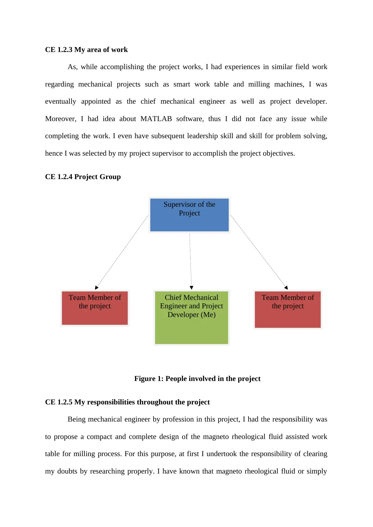
Supervisor of the
Project
Team Member of
the project
Team Member of
the project
Chief Mechanical
Engineer and Project
Developer (Me)
CE 1.2.3 My area of work
As, while accomplishing the project works, I had experiences in similar field work
regarding mechanical projects such as smart work table and milling machines, I was
eventually appointed as the chief mechanical engineer as well as project developer.
Moreover, I had idea about MATLAB software, thus I did not face any issue while
completing the work. I even have subsequent leadership skill and skill for problem solving,
hence I was selected by my project supervisor to accomplish the project objectives.
CE 1.2.4 Project Group
Figure 1: People involved in the project
CE 1.2.5 My responsibilities throughout the project
Being mechanical engineer by profession in this project, I had the responsibility was
to propose a compact and complete design of the magneto rheological fluid assisted work
table for milling process. For this purpose, at first I undertook the responsibility of clearing
my doubts by researching properly. I have known that magneto rheological fluid or simply
⊘ This is a preview!⊘
Do you want full access?
Subscribe today to unlock all pages.

Trusted by 1+ million students worldwide
MR fluid is the kind of smart fluid that is extremely effective for designing a smart work
table. The magnetic particles are micro meter and nano meter scale ellipsoids or spheres that
are eventually suspended in the carrier oil and are distributed randomly. I even learned about
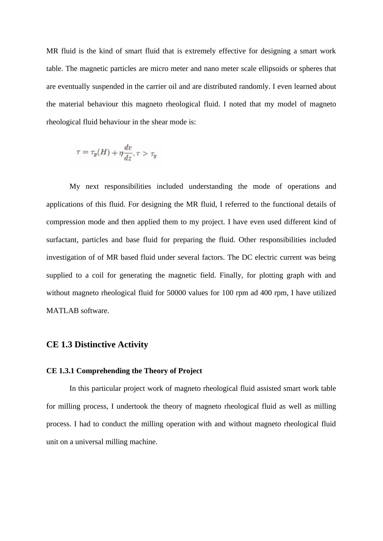
the material behaviour this magneto rheological fluid. I noted that my model of magneto
rheological fluid behaviour in the shear mode is:
My next responsibilities included understanding the mode of operations and
applications of this fluid. For designing the MR fluid, I referred to the functional details of
compression mode and then applied them to my project. I have even used different kind of
surfactant, particles and base fluid for preparing the fluid. Other responsibilities included
investigation of of MR based fluid under several factors. The DC electric current was being
supplied to a coil for generating the magnetic field. Finally, for plotting graph with and
without magneto rheological fluid for 50000 values for 100 rpm ad 400 rpm, I have utilized
MATLAB software.
CE 1.3 Distinctive Activity
CE 1.3.1 Comprehending the Theory of Project
In this particular project work of magneto rheological fluid assisted smart work table
for milling process, I undertook the theory of magneto rheological fluid as well as milling
process. I had to conduct the milling operation with and without magneto rheological fluid
unit on a universal milling machine.
Paraphrase This Document
Need a fresh take? Get an instant paraphrase of this document with our AI Paraphraser
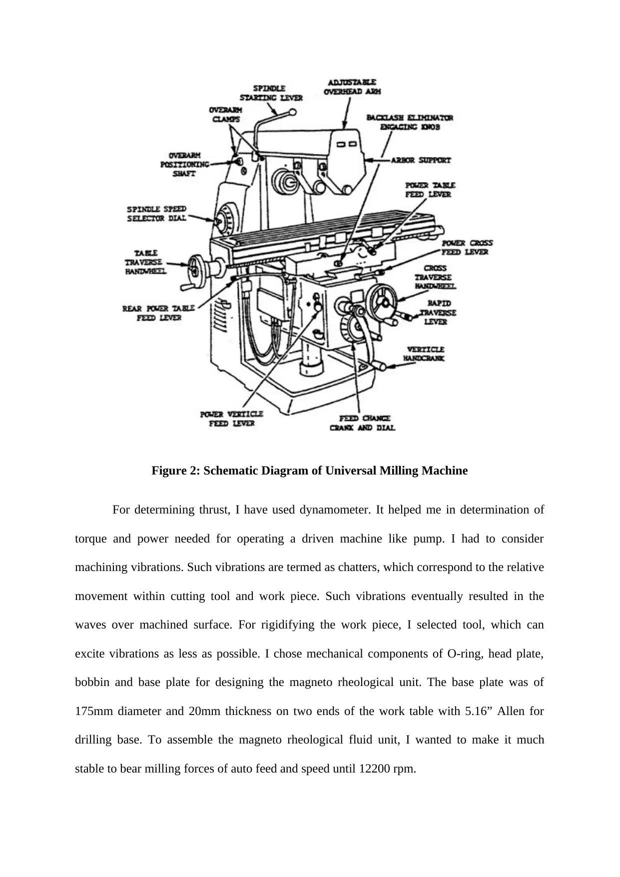
Figure 2: Schematic Diagram of Universal Milling Machine
For determining thrust, I have used dynamometer. It helped me in determination of
torque and power needed for operating a driven machine like pump. I had to consider
machining vibrations. Such vibrations are termed as chatters, which correspond to the relative
movement within cutting tool and work piece. Such vibrations eventually resulted in the
waves over machined surface. For rigidifying the work piece, I selected tool, which can
excite vibrations as less as possible. I chose mechanical components of O-ring, head plate,
bobbin and base plate for designing the magneto rheological unit. The base plate was of
175mm diameter and 20mm thickness on two ends of the work table with 5.16” Allen for
drilling base. To assemble the magneto rheological fluid unit, I wanted to make it much
stable to bear milling forces of auto feed and speed until 12200 rpm.
CE 1.3.2 Engineering knowledge and skills applied in the project
To execute this project work, I had successfully applied each and every core skill and
knowledge for mechanical engineering and magneto rheological fluid. The distinctive
knowledge regarding complete working principle of MR unit and milling process were then
applied in this work. Furthermore, I have even applied my major skills of logical reasoning.
For completion of the project work, I also had to use my knowledge of fluid mechanics and
ignition system. For simulation and graph plotting, I have used my knowledge of MATLAB
software.
CE 1.3.3 Accomplishment and Task Performed
I had successfully accomplished this project of MR fluid assisted smart work table for
milling process. I fabricated the MR unite at the machine stop at SRM University with the
help of several machining operations according to the requirements. I selected the materials
utilized for the MR unit fabrication of mild steel of the required composition. For interfacing
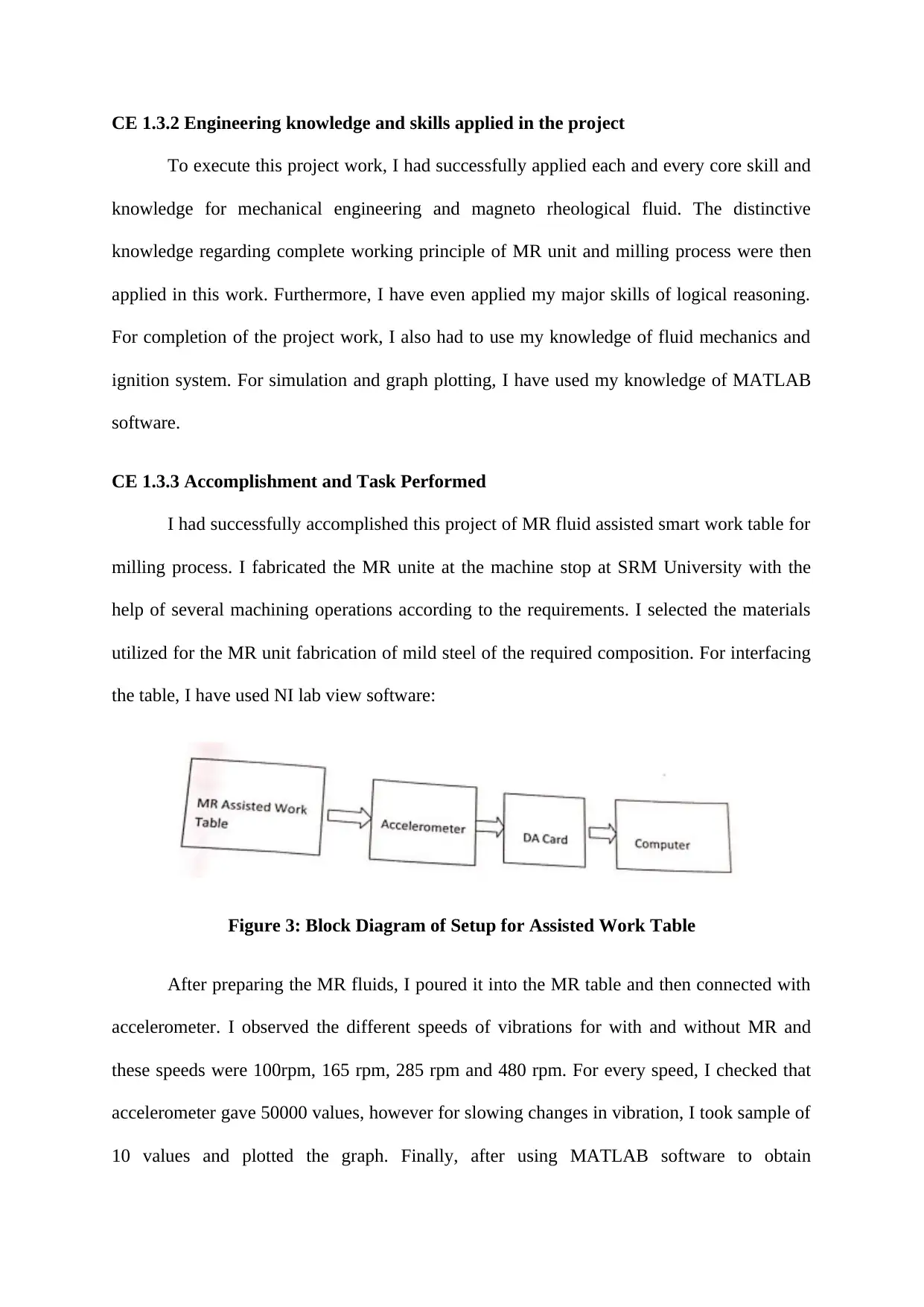
the table, I have used NI lab view software:
Figure 3: Block Diagram of Setup for Assisted Work Table
After preparing the MR fluids, I poured it into the MR table and then connected with
accelerometer. I observed the different speeds of vibrations for with and without MR and
these speeds were 100rpm, 165 rpm, 285 rpm and 480 rpm. For every speed, I checked that
accelerometer gave 50000 values, however for slowing changes in vibration, I took sample of
10 values and plotted the graph. Finally, after using MATLAB software to obtain
⊘ This is a preview!⊘
Do you want full access?
Subscribe today to unlock all pages.

Trusted by 1+ million students worldwide
acceleration amplitudes, I checked that the vibrations could be dampened with MR fluid
assisted work.
CE 1.3.4 Identified issues and their solutions
1.3.4.1 Issues
The former technical difficulty, which I have faced within the project was while
making the project cost effective. Although, I had to ensure that this project does not incur
huge costs, I was unable to reduce the manufacturing costs in the beginning. This created a
major issue as one of the objective was not being followed. The second distinctive technical
difficulty that I have confronted in this particular project was during thermal insulation. Due
to some issue, the thermal insulation could not be achieved in the first go and this brought
delay in my project.
1.3.4.2 Solutions
I was able to find out relevant and suitable solutions for the two technical difficulties
in this project. For the very first issue of manufacturing cost, I consulted with the supplier and
my supervisor. We made an entirely new budget plan and hence finally was able to remove
this issue effectively. For the next issue of thermal insulation, I gave the solution to use
specially engineered method with materials, shapes and objects.
CE 1.3.5 Plan to produce creative and innovative work
I had to make a plan for my team and team members so that distinctive innovative
works are being completed efficiently. This subsequent planning was extremely helpful to us
for making our project successful. Furthermore, I decided to identify the errors properly.
Paraphrase This Document
Need a fresh take? Get an instant paraphrase of this document with our AI Paraphraser
CE 1.4 Project Review
CE 1.4.1 Project Overview
This complete project was executed only after consideration of few important and the
subsequent characteristics of MR fluid unit and milling process. I followed all the
specifications for making the project extremely effective and efficient. The smart worktable
was designed in such a manner that it could be used in every specification.
CE 1.4.2 My Contribution to work
I was selected as the developer of the project and mechanical engineer within the
project. I had completed my task after designing a MR fluid assisted smart worktable that
could bring out better efficiency and results on universal milling machine at different speed
of 100rpm, 165 rpm, 285 rpm and 480 rpm. My other contributions included eradicating of
errors.
1 out of 8
Related Documents
Your All-in-One AI-Powered Toolkit for Academic Success.
+13062052269
info@desklib.com
Available 24*7 on WhatsApp / Email
![[object Object]](/_next/static/media/star-bottom.7253800d.svg)
Unlock your academic potential
Copyright © 2020–2025 A2Z Services. All Rights Reserved. Developed and managed by ZUCOL.


