Detailed Report: Central Heating System Design & Heat Loss Analysis
VerifiedAdded on 2023/06/12
|22
|3821
|404
Report
AI Summary
This report provides a detailed analysis and design of a central heating system for a bungalow, focusing on liquid stream perspectives and heat exchange principles. The system utilizes a 42 kW heater with a 20°C temperature difference between the water inlet and outlet, employing heat transfer edges for efficient heating. The report includes comprehensive heat loss calculations, considering factors such as U-values for the roof and walls, fabric loss, and ventilation loss for each room on the first floor. Various design considerations, including room heights and air changes per hour, are taken into account to determine the type and amount of emitters required for each room, ensuring an effective and energy-efficient heating solution for the bungalow.
Central heating system of Bungalow
Prepared by,
Name:
Student Id:
Course:
1 | P a g e
Prepared by,
Name:
Student Id:
Course:
1 | P a g e
Paraphrase This Document
Need a fresh take? Get an instant paraphrase of this document with our AI Paraphraser
Introduction
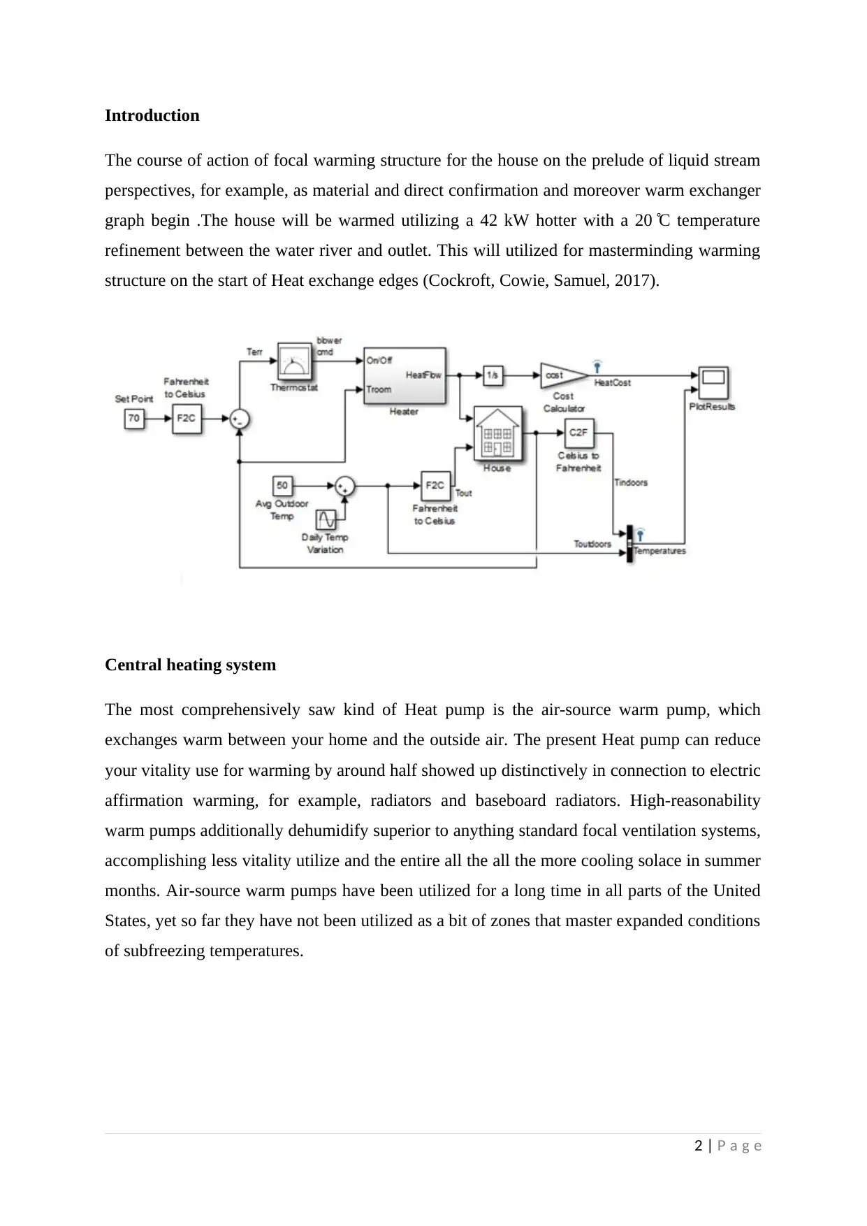
The course of action of focal warming structure for the house on the prelude of liquid stream
perspectives, for example, as material and direct confirmation and moreover warm exchanger
graph begin .The house will be warmed utilizing a 42 kW hotter with a 20 ̊ C temperature
refinement between the water river and outlet. This will utilized for masterminding warming
structure on the start of Heat exchange edges (Cockroft, Cowie, Samuel, 2017).
Central heating system
The most comprehensively saw kind of Heat pump is the air-source warm pump, which
exchanges warm between your home and the outside air. The present Heat pump can reduce
your vitality use for warming by around half showed up distinctively in connection to electric
affirmation warming, for example, radiators and baseboard radiators. High-reasonability
warm pumps additionally dehumidify superior to anything standard focal ventilation systems,
accomplishing less vitality utilize and the entire all the all the more cooling solace in summer
months. Air-source warm pumps have been utilized for a long time in all parts of the United
States, yet so far they have not been utilized as a bit of zones that master expanded conditions
of subfreezing temperatures.
2 | P a g e
Heat transfer
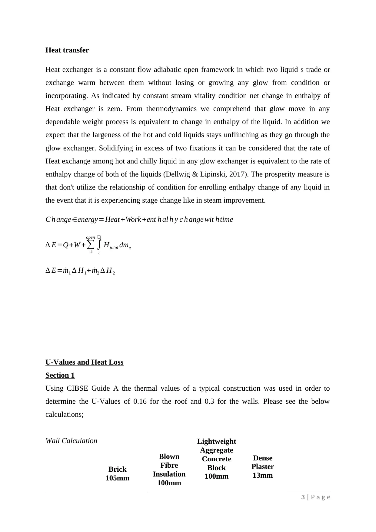
Heat exchanger is a constant flow adiabatic open framework in which two liquid s trade or
exchange warm between them without losing or growing any glow from condition or
incorporating. As indicated by constant stream vitality condition net change in enthalpy of
Heat exchanger is zero. From thermodynamics we comprehend that glow move in any
dependable weight process is equivalent to change in enthalpy of the liquid. In addition we
expect that the largeness of the hot and cold liquids stays unflinching as they go through the
glow exchanger. Solidifying in excess of two fixations it can be considered that the rate of
Heat exchange among hot and chilly liquid in any glow exchanger is equivalent to the rate of
enthalpy change of both of the liquids (Dellwig & Lipinski, 2017). The prosperity measure is
that don't utilize the relationship of condition for enrolling enthalpy change of any liquid in
the event that it is experiencing stage change like in steam improvement.
C h ange ∈energy=Heat +Work +ent h al h y c h ange wit h time
∆ E=Q+W +∑❑
open
∫
t
❑
Htotal dme
∆ E= ˙m1 ∆ H1+ ˙m2 ∆ H2
U-Values and Heat Loss
Section 1
Using CIBSE Guide A the thermal values of a typical construction was used in order to
determine the U-Values of 0.16 for the roof and 0.3 for the walls. Please see the below
calculations;
Wall Calculation
3 | P a g e
Brick
105mm
Blown
Fibre
Insulation
100mm
Lightweight
Aggregate
Concrete
Block
100mm
Dense
Plaster
13mm
⊘ This is a preview!⊘
Do you want full access?
Subscribe today to unlock all pages.

Trusted by 1+ million students worldwide
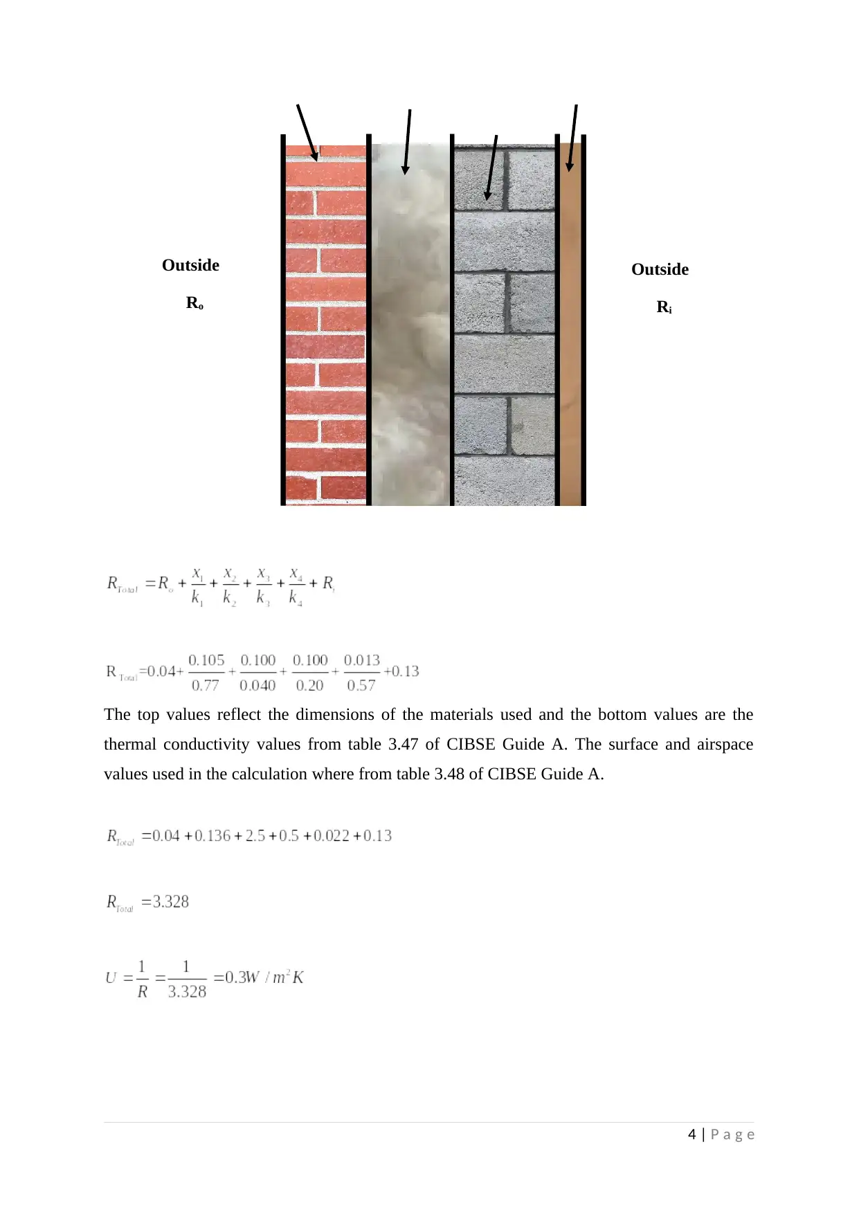
The top values reflect the dimensions of the materials used and the bottom values are the
thermal conductivity values from table 3.47 of CIBSE Guide A. The surface and airspace
values used in the calculation where from table 3.48 of CIBSE Guide A.
4 | P a g e
Outside
Ro
Outside
Ri
thermal conductivity values from table 3.47 of CIBSE Guide A. The surface and airspace
values used in the calculation where from table 3.48 of CIBSE Guide A.
4 | P a g e
Outside
Ro
Outside
Ri
Paraphrase This Document
Need a fresh take? Get an instant paraphrase of this document with our AI Paraphraser
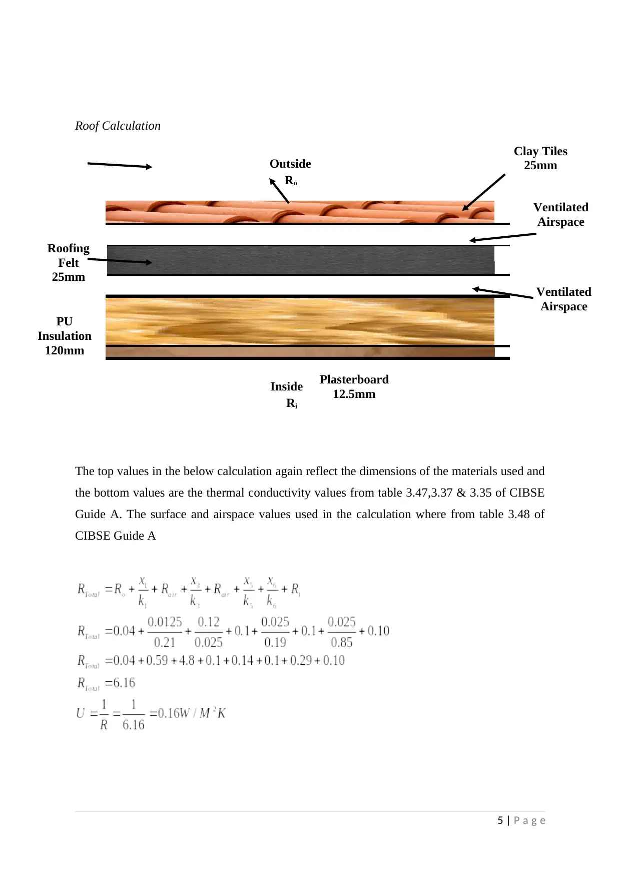
Roof Calculation
The top values in the below calculation again reflect the dimensions of the materials used and
the bottom values are the thermal conductivity values from table 3.47,3.37 & 3.35 of CIBSE
Guide A. The surface and airspace values used in the calculation where from table 3.48 of
CIBSE Guide A
5 | P a g e
Outside
Ro
Inside
Ri
Clay Tiles
25mm
Ventilated
Airspace
Ventilated
Airspace
Roofing
Felt
25mm
PU
Insulation
120mm
Plasterboard
12.5mm
Section 2
The purpose of this assignment is to design the heating system by choosing either emitters,
boilers, pumps etc. for the building layout provided. The choice of system selected will be
identified within this report and all calculations and considerations will be taken into account
when doing so.
Within this report the heat loss calculations will need to be collated for all the rooms on the
first floor, this will then determine what type of emitters are required followed by the amount
of heat required for each room.
Design Considerations
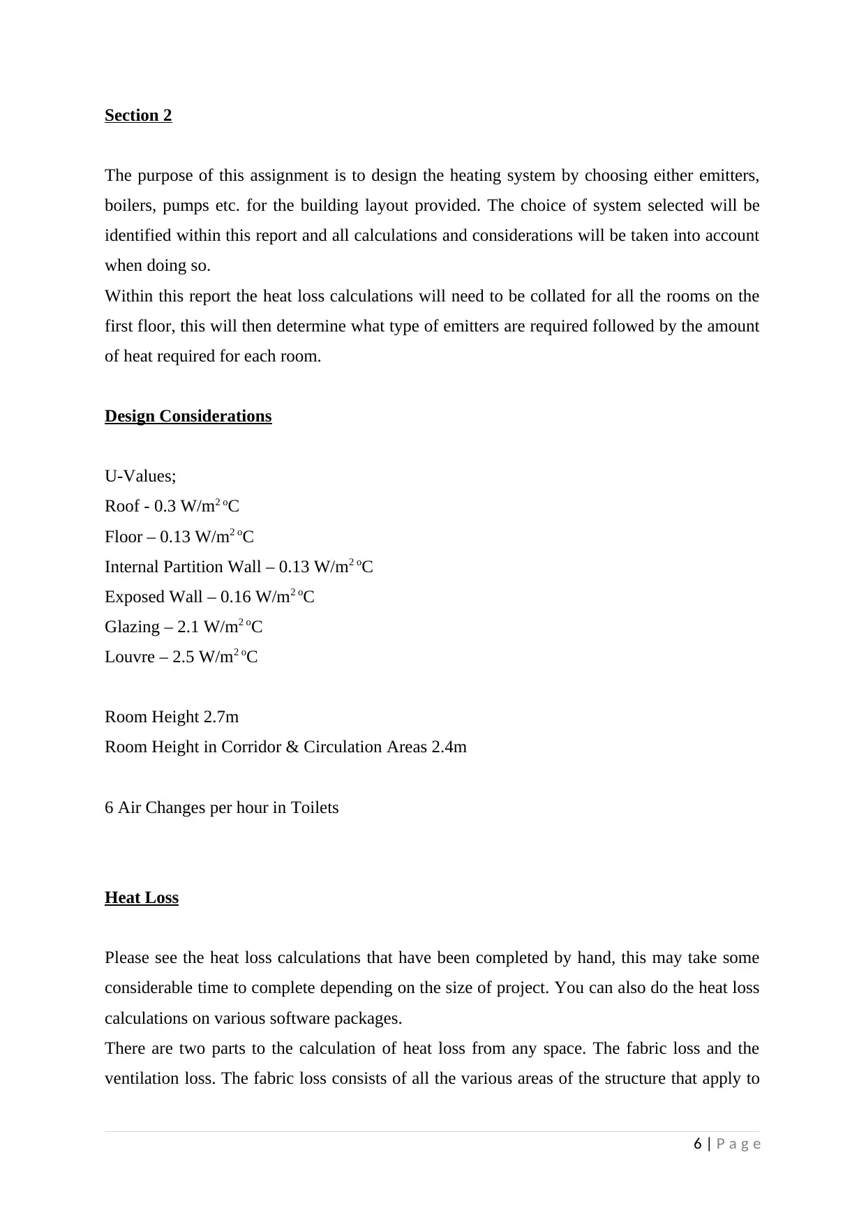
U-Values;
Roof - 0.3 W/m2 oC
Floor – 0.13 W/m2 oC
Internal Partition Wall – 0.13 W/m2 oC
Exposed Wall – 0.16 W/m2 oC
Glazing – 2.1 W/m2 oC
Louvre – 2.5 W/m2 oC
Room Height 2.7m
Room Height in Corridor & Circulation Areas 2.4m
6 Air Changes per hour in Toilets
Heat Loss
Please see the heat loss calculations that have been completed by hand, this may take some
considerable time to complete depending on the size of project. You can also do the heat loss
calculations on various software packages.
There are two parts to the calculation of heat loss from any space. The fabric loss and the
ventilation loss. The fabric loss consists of all the various areas of the structure that apply to
6 | P a g e
⊘ This is a preview!⊘
Do you want full access?
Subscribe today to unlock all pages.

Trusted by 1+ million students worldwide
the space (floor, roof, walls, windows, doors etc.) The ventilation loss is the rate of air change
per hour.
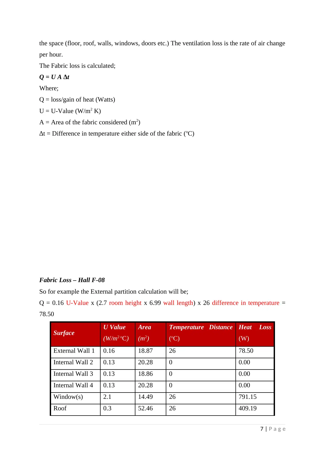
The Fabric loss is calculated;
Q = U A ∆t
Where;
Q = loss/gain of heat (Watts)
U = U-Value (W/m2 K)
A = Area of the fabric considered (m2)
∆t = Difference in temperature either side of the fabric (oC)
Fabric Loss – Hall F-08
So for example the External partition calculation will be;
Q = 0.16 U-Value x (2.7 room height x 6.99 wall length) x 26 difference in temperature =
78.50
Surface U Value
(W/m2 oC)
Area
(m2)
Temperature Distance
(oC)
Heat Loss
(W)
External Wall 1 0.16 18.87 26 78.50
Internal Wall 2 0.13 20.28 0 0.00
Internal Wall 3 0.13 18.86 0 0.00
Internal Wall 4 0.13 20.28 0 0.00
Window(s) 2.1 14.49 26 791.15
Roof 0.3 52.46 26 409.19
7 | P a g e
Paraphrase This Document
Need a fresh take? Get an instant paraphrase of this document with our AI Paraphraser
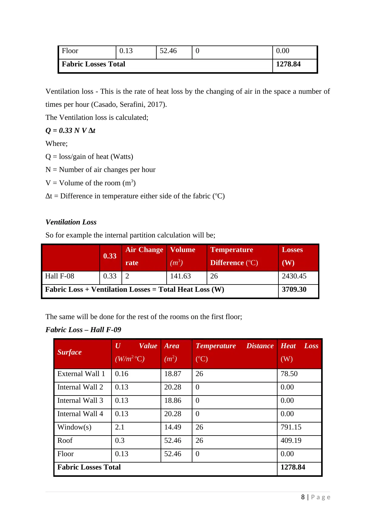
Floor 0.13 52.46 0 0.00
Fabric Losses Total 1278.84
Ventilation loss - This is the rate of heat loss by the changing of air in the space a number of
times per hour (Casado, Serafini, 2017).
The Ventilation loss is calculated;
Q = 0.33 N V ∆t
Where;
Q = loss/gain of heat (Watts)
N = Number of air changes per hour
V = Volume of the room (m3)
∆t = Difference in temperature either side of the fabric (oC)
Ventilation Loss
So for example the internal partition calculation will be;
0.33 Air Change
rate
Volume
(m3)
Temperature
Difference (oC)
Losses
(W)
Hall F-08 0.33 2 141.63 26 2430.45
Fabric Loss + Ventilation Losses = Total Heat Loss (W) 3709.30
The same will be done for the rest of the rooms on the first floor;
Fabric Loss – Hall F-09
Surface U Value
(W/m2 oC)
Area
(m2)
Temperature Distance
(oC)
Heat Loss
(W)
External Wall 1 0.16 18.87 26 78.50
Internal Wall 2 0.13 20.28 0 0.00
Internal Wall 3 0.13 18.86 0 0.00
Internal Wall 4 0.13 20.28 0 0.00
Window(s) 2.1 14.49 26 791.15
Roof 0.3 52.46 26 409.19
Floor 0.13 52.46 0 0.00
Fabric Losses Total 1278.84
8 | P a g e
Fabric Losses Total 1278.84
Ventilation loss - This is the rate of heat loss by the changing of air in the space a number of
times per hour (Casado, Serafini, 2017).
The Ventilation loss is calculated;
Q = 0.33 N V ∆t
Where;
Q = loss/gain of heat (Watts)
N = Number of air changes per hour
V = Volume of the room (m3)
∆t = Difference in temperature either side of the fabric (oC)
Ventilation Loss
So for example the internal partition calculation will be;
0.33 Air Change
rate
Volume
(m3)
Temperature
Difference (oC)
Losses
(W)
Hall F-08 0.33 2 141.63 26 2430.45
Fabric Loss + Ventilation Losses = Total Heat Loss (W) 3709.30
The same will be done for the rest of the rooms on the first floor;
Fabric Loss – Hall F-09
Surface U Value
(W/m2 oC)
Area
(m2)
Temperature Distance
(oC)
Heat Loss
(W)
External Wall 1 0.16 18.87 26 78.50
Internal Wall 2 0.13 20.28 0 0.00
Internal Wall 3 0.13 18.86 0 0.00
Internal Wall 4 0.13 20.28 0 0.00
Window(s) 2.1 14.49 26 791.15
Roof 0.3 52.46 26 409.19
Floor 0.13 52.46 0 0.00
Fabric Losses Total 1278.84
8 | P a g e
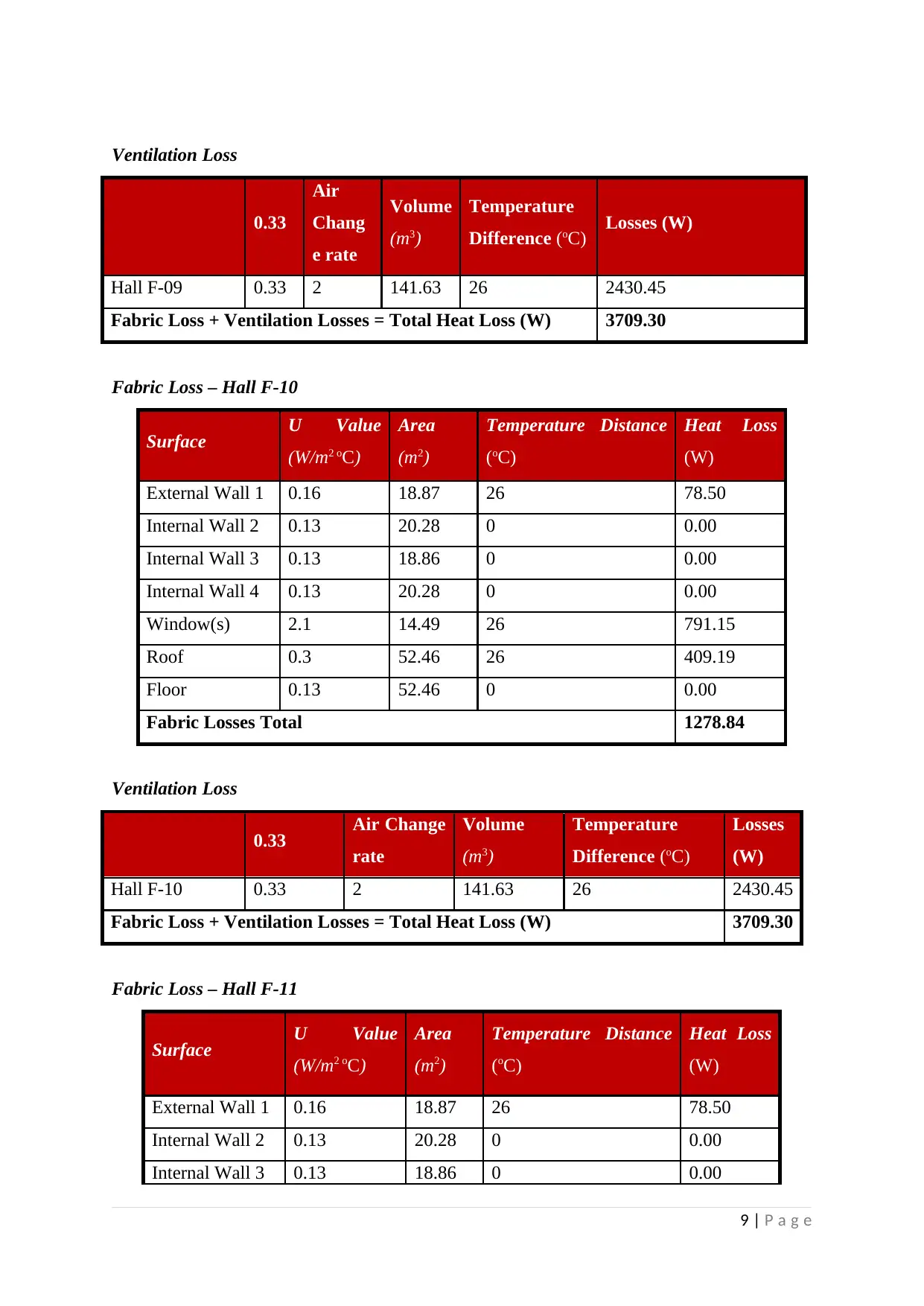
Ventilation Loss
0.33
Air
Chang
e rate
Volume
(m3)
Temperature
Difference (oC) Losses (W)
Hall F-09 0.33 2 141.63 26 2430.45
Fabric Loss + Ventilation Losses = Total Heat Loss (W) 3709.30
Fabric Loss – Hall F-10
Surface U Value
(W/m2 oC)
Area
(m2)
Temperature Distance
(oC)
Heat Loss
(W)
External Wall 1 0.16 18.87 26 78.50
Internal Wall 2 0.13 20.28 0 0.00
Internal Wall 3 0.13 18.86 0 0.00
Internal Wall 4 0.13 20.28 0 0.00
Window(s) 2.1 14.49 26 791.15
Roof 0.3 52.46 26 409.19
Floor 0.13 52.46 0 0.00
Fabric Losses Total 1278.84
Ventilation Loss
0.33 Air Change
rate
Volume
(m3)
Temperature
Difference (oC)
Losses
(W)
Hall F-10 0.33 2 141.63 26 2430.45
Fabric Loss + Ventilation Losses = Total Heat Loss (W) 3709.30
Fabric Loss – Hall F-11
Surface U Value
(W/m2 oC)
Area
(m2)
Temperature Distance
(oC)
Heat Loss
(W)
External Wall 1 0.16 18.87 26 78.50
Internal Wall 2 0.13 20.28 0 0.00
Internal Wall 3 0.13 18.86 0 0.00
9 | P a g e
⊘ This is a preview!⊘
Do you want full access?
Subscribe today to unlock all pages.

Trusted by 1+ million students worldwide
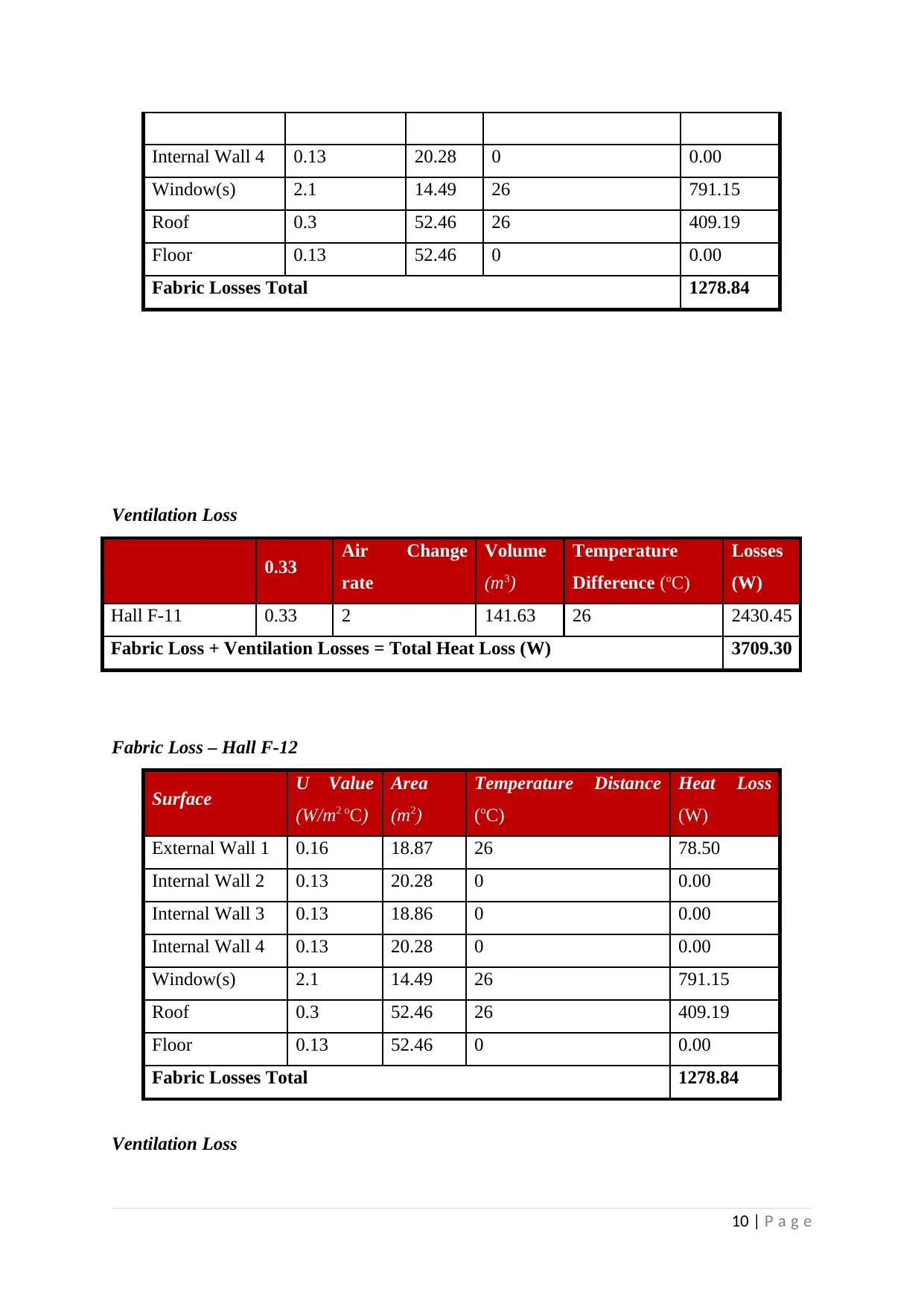
Internal Wall 4 0.13 20.28 0 0.00
Window(s) 2.1 14.49 26 791.15
Roof 0.3 52.46 26 409.19
Floor 0.13 52.46 0 0.00
Fabric Losses Total 1278.84
Ventilation Loss
0.33 Air Change
rate
Volume
(m3)
Temperature
Difference (oC)
Losses
(W)
Hall F-11 0.33 2 141.63 26 2430.45
Fabric Loss + Ventilation Losses = Total Heat Loss (W) 3709.30
Fabric Loss – Hall F-12
Surface U Value
(W/m2 oC)
Area
(m2)
Temperature Distance
(oC)
Heat Loss
(W)
External Wall 1 0.16 18.87 26 78.50
Internal Wall 2 0.13 20.28 0 0.00
Internal Wall 3 0.13 18.86 0 0.00
Internal Wall 4 0.13 20.28 0 0.00
Window(s) 2.1 14.49 26 791.15
Roof 0.3 52.46 26 409.19
Floor 0.13 52.46 0 0.00
Fabric Losses Total 1278.84
Ventilation Loss
10 | P a g e
Window(s) 2.1 14.49 26 791.15
Roof 0.3 52.46 26 409.19
Floor 0.13 52.46 0 0.00
Fabric Losses Total 1278.84
Ventilation Loss
0.33 Air Change
rate
Volume
(m3)
Temperature
Difference (oC)
Losses
(W)
Hall F-11 0.33 2 141.63 26 2430.45
Fabric Loss + Ventilation Losses = Total Heat Loss (W) 3709.30
Fabric Loss – Hall F-12
Surface U Value
(W/m2 oC)
Area
(m2)
Temperature Distance
(oC)
Heat Loss
(W)
External Wall 1 0.16 18.87 26 78.50
Internal Wall 2 0.13 20.28 0 0.00
Internal Wall 3 0.13 18.86 0 0.00
Internal Wall 4 0.13 20.28 0 0.00
Window(s) 2.1 14.49 26 791.15
Roof 0.3 52.46 26 409.19
Floor 0.13 52.46 0 0.00
Fabric Losses Total 1278.84
Ventilation Loss
10 | P a g e
Paraphrase This Document
Need a fresh take? Get an instant paraphrase of this document with our AI Paraphraser
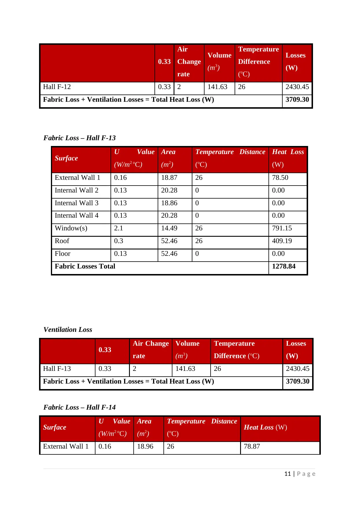
0.33
Air
Change
rate
Volume
(m3)
Temperature
Difference
(oC)
Losses
(W)
Hall F-12 0.33 2 141.63 26 2430.45
Fabric Loss + Ventilation Losses = Total Heat Loss (W) 3709.30
Fabric Loss – Hall F-13
Surface U Value
(W/m2 oC)
Area
(m2)
Temperature Distance
(oC)
Heat Loss
(W)
External Wall 1 0.16 18.87 26 78.50
Internal Wall 2 0.13 20.28 0 0.00
Internal Wall 3 0.13 18.86 0 0.00
Internal Wall 4 0.13 20.28 0 0.00
Window(s) 2.1 14.49 26 791.15
Roof 0.3 52.46 26 409.19
Floor 0.13 52.46 0 0.00
Fabric Losses Total 1278.84
Ventilation Loss
0.33 Air Change
rate
Volume
(m3)
Temperature
Difference (oC)
Losses
(W)
Hall F-13 0.33 2 141.63 26 2430.45
Fabric Loss + Ventilation Losses = Total Heat Loss (W) 3709.30
Fabric Loss – Hall F-14
Surface U Value
(W/m2 oC)
Area
(m2)
Temperature Distance
(oC) Heat Loss (W)
External Wall 1 0.16 18.96 26 78.87
11 | P a g e
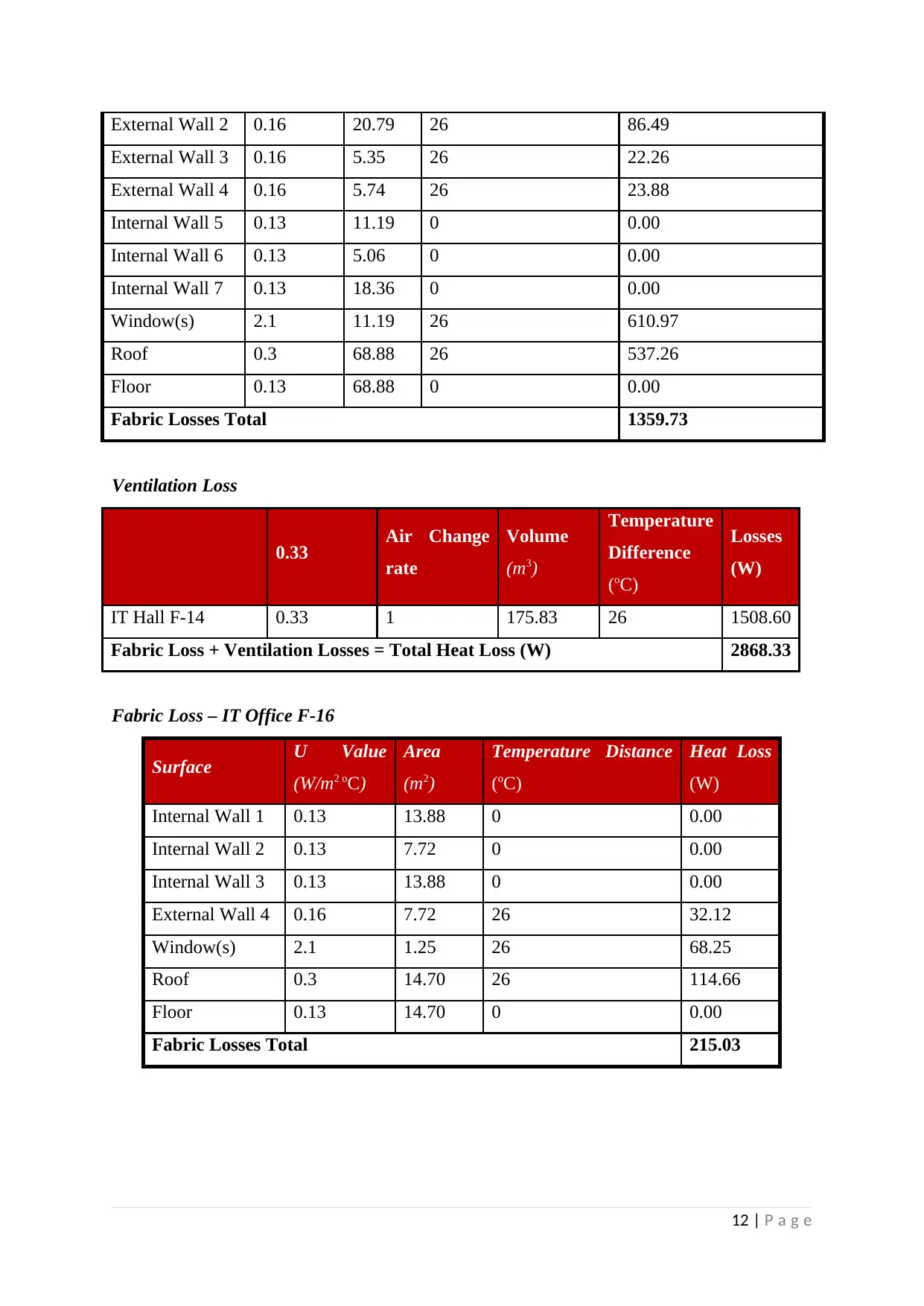
External Wall 2 0.16 20.79 26 86.49
External Wall 3 0.16 5.35 26 22.26
External Wall 4 0.16 5.74 26 23.88
Internal Wall 5 0.13 11.19 0 0.00
Internal Wall 6 0.13 5.06 0 0.00
Internal Wall 7 0.13 18.36 0 0.00
Window(s) 2.1 11.19 26 610.97
Roof 0.3 68.88 26 537.26
Floor 0.13 68.88 0 0.00
Fabric Losses Total 1359.73
Ventilation Loss
0.33 Air Change
rate
Volume
(m3)
Temperature
Difference
(oC)
Losses
(W)
IT Hall F-14 0.33 1 175.83 26 1508.60
Fabric Loss + Ventilation Losses = Total Heat Loss (W) 2868.33
Fabric Loss – IT Office F-16
Surface U Value
(W/m2 oC)
Area
(m2)
Temperature Distance
(oC)
Heat Loss
(W)
Internal Wall 1 0.13 13.88 0 0.00
Internal Wall 2 0.13 7.72 0 0.00
Internal Wall 3 0.13 13.88 0 0.00
External Wall 4 0.16 7.72 26 32.12
Window(s) 2.1 1.25 26 68.25
Roof 0.3 14.70 26 114.66
Floor 0.13 14.70 0 0.00
Fabric Losses Total 215.03
12 | P a g e
⊘ This is a preview!⊘
Do you want full access?
Subscribe today to unlock all pages.

Trusted by 1+ million students worldwide
1 out of 22
Your All-in-One AI-Powered Toolkit for Academic Success.
+13062052269
info@desklib.com
Available 24*7 on WhatsApp / Email
![[object Object]](/_next/static/media/star-bottom.7253800d.svg)
Unlock your academic potential
Copyright © 2020–2026 A2Z Services. All Rights Reserved. Developed and managed by ZUCOL.