Centre of Pressure Experiment: Analyzing Fluid Thrust vs. Height
VerifiedAdded on 2023/06/04
|11
|2354
|159
Practical Assignment
AI Summary
This report details an experiment conducted to investigate the relationship between water height and fluid thrust on vertical and inclined planes, utilizing the TecQuipment Centre of Pressure Apparatus. The experiment compares theoretical and experimental moment values resulting from hydrostatic force on partially and fully submerged planes. The methodology involves measuring the weight required to balance the hydrostatic force at varying water heights, calculating actual moments, and comparing these with theoretical moments derived from established formulas. The results indicate a linear relationship between moment and water height for fully submerged planes and a non-linear relationship for partially submerged planes, with close agreement between experimental and theoretical values. The conclusion emphasizes the predictability of moments acting on submerged surfaces, crucial for engineering designs involving water containment and resistance.
Centre of Pressure 1
CENTRE OF PRESSURE EXPERIMENT
Name
Course
Professor
University
City/state
Date
CENTRE OF PRESSURE EXPERIMENT
Name
Course
Professor
University
City/state
Date
Paraphrase This Document
Need a fresh take? Get an instant paraphrase of this document with our AI Paraphraser
Centre of Pressure 2
Centre of Pressure Experiment
1. Introduction
When water is at rest or moving at a relatively slow velocity, it exerts a hydrostatic
pressure or force on the walls of engineering structures such as dams, canals, large ducts, etc.
The hydrostatic force varies with the angle at which it is acting on the structure and also changes
with changing height (Claydon, 2015). Engineers should understand how to predict the
hydrostatic force so as to ensure that they design structures that are able to resist the force. The
aim of this experiment is to establish the relationship between height of water and fluid thrust
(moment of force) acting on a vertical plane (0 degrees) and on an inclined plane (30 degrees).
The experiment was performed using TecQuipment Centre of Pressure Apparatus. The
experimental values obtained of moment resulting from a hydrostatic force acting on a partially
submerged and fully submerged vertical plane surface was compared with theoretical values.
This phenomenon is similar to parallel-axis theorem, which states that moment of inertia is
directly proportional to the distance of the rotation axis from the centre of mass (Moore, (n.d.));
(Smith, 2018).
2. Theory
The hydrostatic pressure acts normal to the plane surface and generates thrust on it. The
pressure forces result to a single force that also acts normal to the plane surface. The pressure
increases linearly with the water depth and therefore the resultant single force acts through a
lower point known as te centre of pressure.
Weight is converted into Newtons using the following: 1,000 g = 1 Kg = 9.81 N.
Centre of Pressure 3
A plane is said to be partially submerged if only part of the plane surface is covered with
water. On the other hand, a plane is said to be fully covered if the plane surface is completely
covered with water. In this case, the plane was partially covered when the height/level of water
(h) was greater than 0.1 m for the vertical (0 degree) plane or greater than 0.0866 m for the
inclined (30 degree) plane. Also, the plane was fully submerged when the height/level of water
(h) was less than 0.1 m for the vertical (0 degree) plane or less than 0.0866 m for the inclined (30
degree) plane.
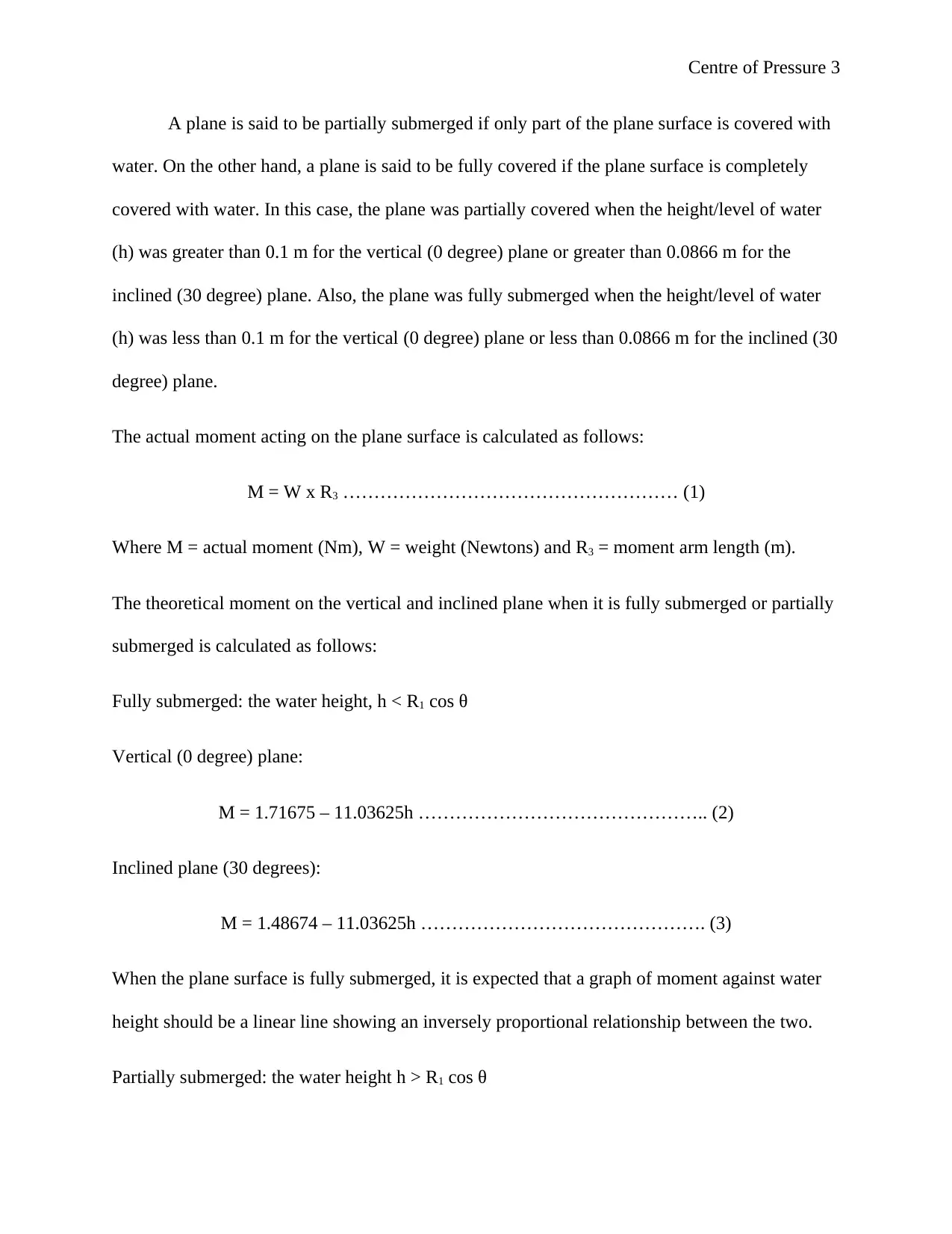
The actual moment acting on the plane surface is calculated as follows:
M = W x R3 ……………………………………………… (1)
Where M = actual moment (Nm), W = weight (Newtons) and R3 = moment arm length (m).
The theoretical moment on the vertical and inclined plane when it is fully submerged or partially
submerged is calculated as follows:
Fully submerged: the water height, h < R1 cos θ
Vertical (0 degree) plane:
M = 1.71675 – 11.03625h ……………………………………….. (2)
Inclined plane (30 degrees):
M = 1.48674 – 11.03625h ………………………………………. (3)
When the plane surface is fully submerged, it is expected that a graph of moment against water
height should be a linear line showing an inversely proportional relationship between the two.
Partially submerged: the water height h > R1 cos θ
⊘ This is a preview!⊘
Do you want full access?
Subscribe today to unlock all pages.

Trusted by 1+ million students worldwide
Centre of Pressure 4
Vertical (0 degree) plane:
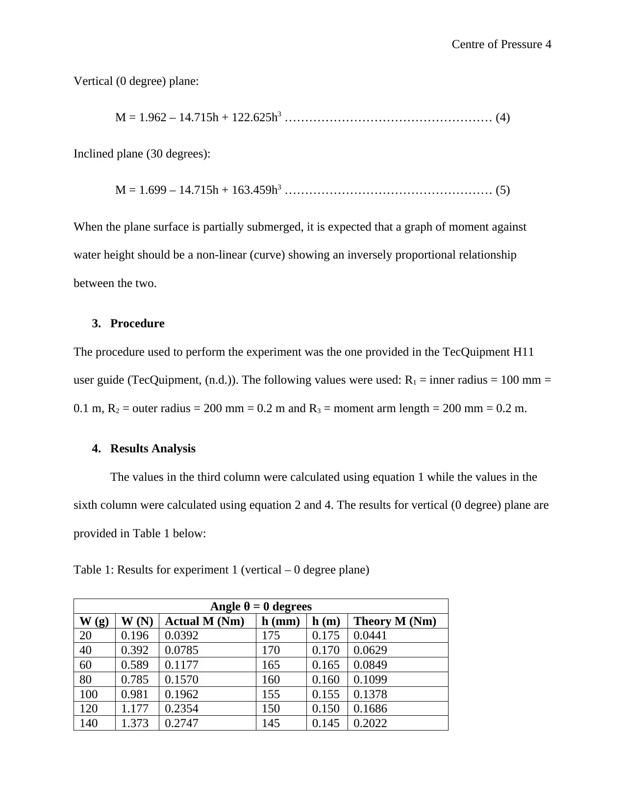
M = 1.962 – 14.715h + 122.625h3 …………………………………………… (4)
Inclined plane (30 degrees):
M = 1.699 – 14.715h + 163.459h3 …………………………………………… (5)
When the plane surface is partially submerged, it is expected that a graph of moment against
water height should be a non-linear (curve) showing an inversely proportional relationship
between the two.
3. Procedure
The procedure used to perform the experiment was the one provided in the TecQuipment H11
user guide (TecQuipment, (n.d.)). The following values were used: R1 = inner radius = 100 mm =
0.1 m, R2 = outer radius = 200 mm = 0.2 m and R3 = moment arm length = 200 mm = 0.2 m.
4. Results Analysis
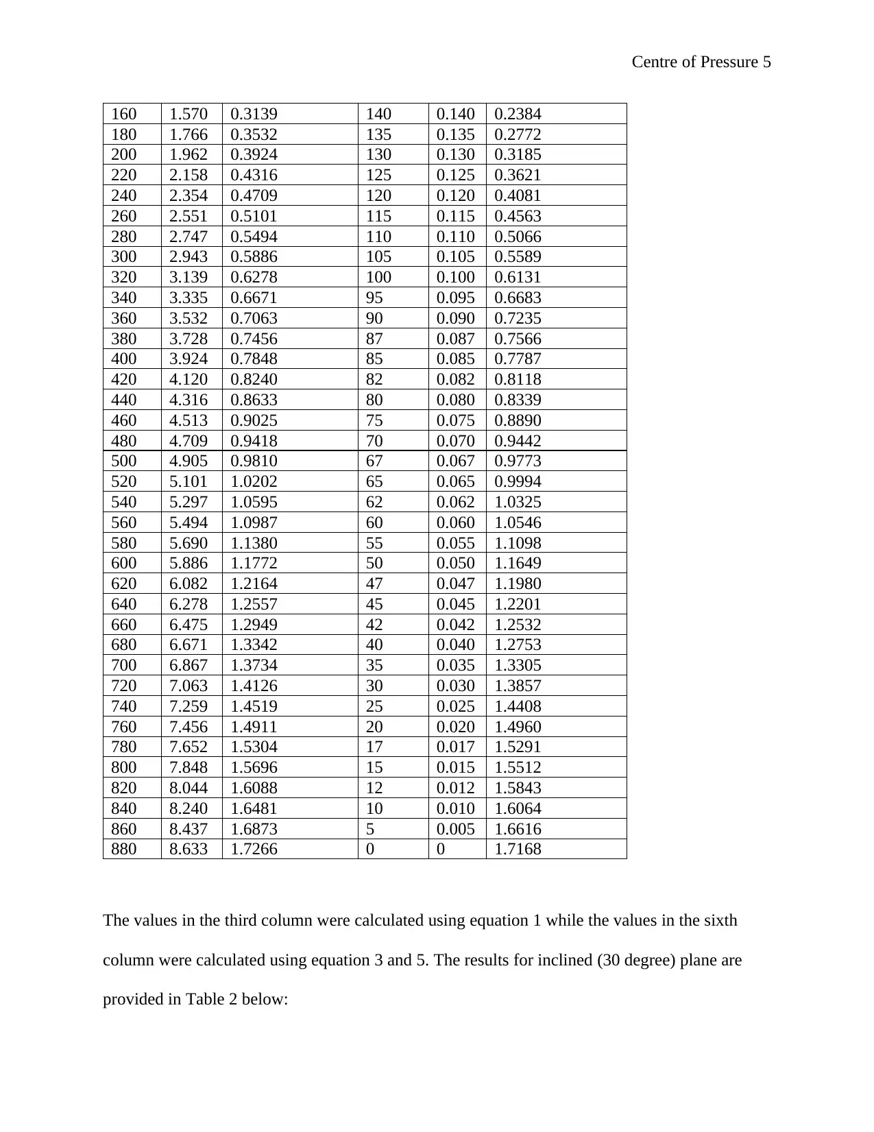
The values in the third column were calculated using equation 1 while the values in the
sixth column were calculated using equation 2 and 4. The results for vertical (0 degree) plane are
provided in Table 1 below:
Table 1: Results for experiment 1 (vertical – 0 degree plane)
Angle θ = 0 degrees
W (g) W (N) Actual M (Nm) h (mm) h (m) Theory M (Nm)
20 0.196 0.0392 175 0.175 0.0441
40 0.392 0.0785 170 0.170 0.0629
60 0.589 0.1177 165 0.165 0.0849
80 0.785 0.1570 160 0.160 0.1099
100 0.981 0.1962 155 0.155 0.1378
120 1.177 0.2354 150 0.150 0.1686
140 1.373 0.2747 145 0.145 0.2022
Paraphrase This Document
Need a fresh take? Get an instant paraphrase of this document with our AI Paraphraser
Centre of Pressure 5
160 1.570 0.3139 140 0.140 0.2384
180 1.766 0.3532 135 0.135 0.2772
200 1.962 0.3924 130 0.130 0.3185
220 2.158 0.4316 125 0.125 0.3621
240 2.354 0.4709 120 0.120 0.4081
260 2.551 0.5101 115 0.115 0.4563
280 2.747 0.5494 110 0.110 0.5066
300 2.943 0.5886 105 0.105 0.5589
320 3.139 0.6278 100 0.100 0.6131
340 3.335 0.6671 95 0.095 0.6683
360 3.532 0.7063 90 0.090 0.7235
380 3.728 0.7456 87 0.087 0.7566
400 3.924 0.7848 85 0.085 0.7787
420 4.120 0.8240 82 0.082 0.8118
440 4.316 0.8633 80 0.080 0.8339
460 4.513 0.9025 75 0.075 0.8890
480 4.709 0.9418 70 0.070 0.9442
500 4.905 0.9810 67 0.067 0.9773
520 5.101 1.0202 65 0.065 0.9994
540 5.297 1.0595 62 0.062 1.0325
560 5.494 1.0987 60 0.060 1.0546
580 5.690 1.1380 55 0.055 1.1098
600 5.886 1.1772 50 0.050 1.1649
620 6.082 1.2164 47 0.047 1.1980
640 6.278 1.2557 45 0.045 1.2201
660 6.475 1.2949 42 0.042 1.2532
680 6.671 1.3342 40 0.040 1.2753
700 6.867 1.3734 35 0.035 1.3305
720 7.063 1.4126 30 0.030 1.3857
740 7.259 1.4519 25 0.025 1.4408
760 7.456 1.4911 20 0.020 1.4960
780 7.652 1.5304 17 0.017 1.5291
800 7.848 1.5696 15 0.015 1.5512
820 8.044 1.6088 12 0.012 1.5843
840 8.240 1.6481 10 0.010 1.6064
860 8.437 1.6873 5 0.005 1.6616
880 8.633 1.7266 0 0 1.7168
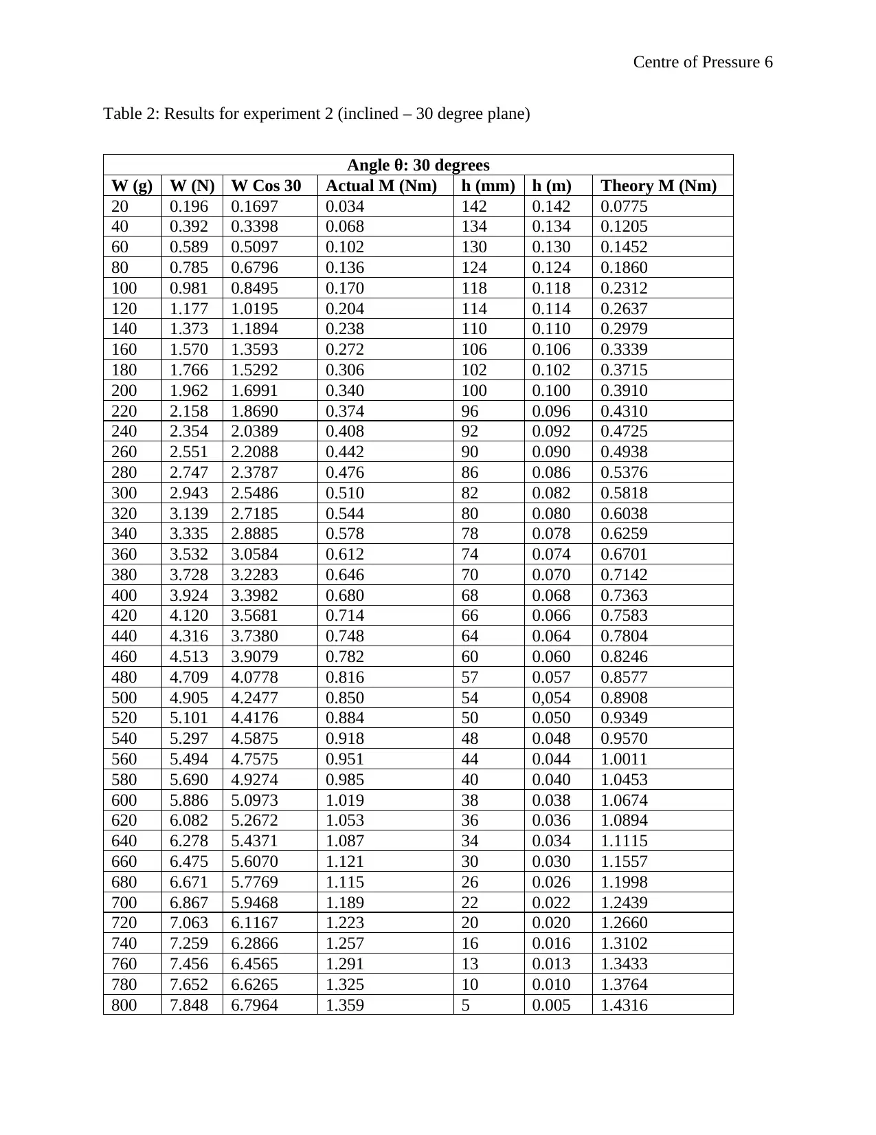
The values in the third column were calculated using equation 1 while the values in the sixth
column were calculated using equation 3 and 5. The results for inclined (30 degree) plane are
provided in Table 2 below:
Centre of Pressure 6
Table 2: Results for experiment 2 (inclined – 30 degree plane)
Angle θ: 30 degrees
W (g) W (N) W Cos 30 Actual M (Nm) h (mm) h (m) Theory M (Nm)
20 0.196 0.1697 0.034 142 0.142 0.0775
40 0.392 0.3398 0.068 134 0.134 0.1205
60 0.589 0.5097 0.102 130 0.130 0.1452
80 0.785 0.6796 0.136 124 0.124 0.1860
100 0.981 0.8495 0.170 118 0.118 0.2312
120 1.177 1.0195 0.204 114 0.114 0.2637
140 1.373 1.1894 0.238 110 0.110 0.2979
160 1.570 1.3593 0.272 106 0.106 0.3339
180 1.766 1.5292 0.306 102 0.102 0.3715
200 1.962 1.6991 0.340 100 0.100 0.3910
220 2.158 1.8690 0.374 96 0.096 0.4310
240 2.354 2.0389 0.408 92 0.092 0.4725
260 2.551 2.2088 0.442 90 0.090 0.4938
280 2.747 2.3787 0.476 86 0.086 0.5376
300 2.943 2.5486 0.510 82 0.082 0.5818
320 3.139 2.7185 0.544 80 0.080 0.6038
340 3.335 2.8885 0.578 78 0.078 0.6259
360 3.532 3.0584 0.612 74 0.074 0.6701
380 3.728 3.2283 0.646 70 0.070 0.7142
400 3.924 3.3982 0.680 68 0.068 0.7363
420 4.120 3.5681 0.714 66 0.066 0.7583
440 4.316 3.7380 0.748 64 0.064 0.7804
460 4.513 3.9079 0.782 60 0.060 0.8246
480 4.709 4.0778 0.816 57 0.057 0.8577
500 4.905 4.2477 0.850 54 0,054 0.8908
520 5.101 4.4176 0.884 50 0.050 0.9349
540 5.297 4.5875 0.918 48 0.048 0.9570
560 5.494 4.7575 0.951 44 0.044 1.0011
580 5.690 4.9274 0.985 40 0.040 1.0453
600 5.886 5.0973 1.019 38 0.038 1.0674
620 6.082 5.2672 1.053 36 0.036 1.0894
640 6.278 5.4371 1.087 34 0.034 1.1115
660 6.475 5.6070 1.121 30 0.030 1.1557
680 6.671 5.7769 1.115 26 0.026 1.1998
700 6.867 5.9468 1.189 22 0.022 1.2439
720 7.063 6.1167 1.223 20 0.020 1.2660
740 7.259 6.2866 1.257 16 0.016 1.3102
760 7.456 6.4565 1.291 13 0.013 1.3433
780 7.652 6.6265 1.325 10 0.010 1.3764
800 7.848 6.7964 1.359 5 0.005 1.4316
⊘ This is a preview!⊘
Do you want full access?
Subscribe today to unlock all pages.

Trusted by 1+ million students worldwide
Centre of Pressure 7
820 8.044 6.9663 1.393 2 0.002 1.4647
840 8.240 7.1362 1.427 0 0 1.4867
860 8.437 7.3061 1.461 -2 -0.002 1.5088
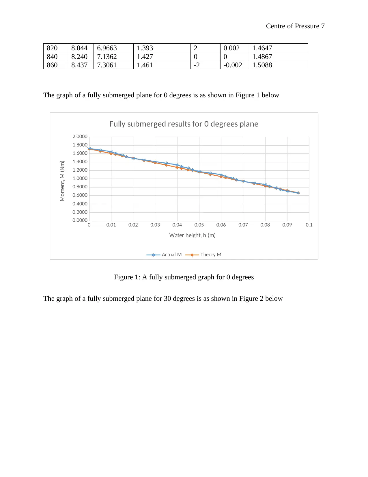
The graph of a fully submerged plane for 0 degrees is as shown in Figure 1 below
0 0.01 0.02 0.03 0.04 0.05 0.06 0.07 0.08 0.09 0.1
0.0000
0.2000
0.4000
0.6000
0.8000
1.0000
1.2000
1.4000
1.6000
1.8000
2.0000
Fully submerged results for 0 degrees plane
Actual M Theory M
Water height, h (m)
Moment, M (Nm)
Figure 1: A fully submerged graph for 0 degrees
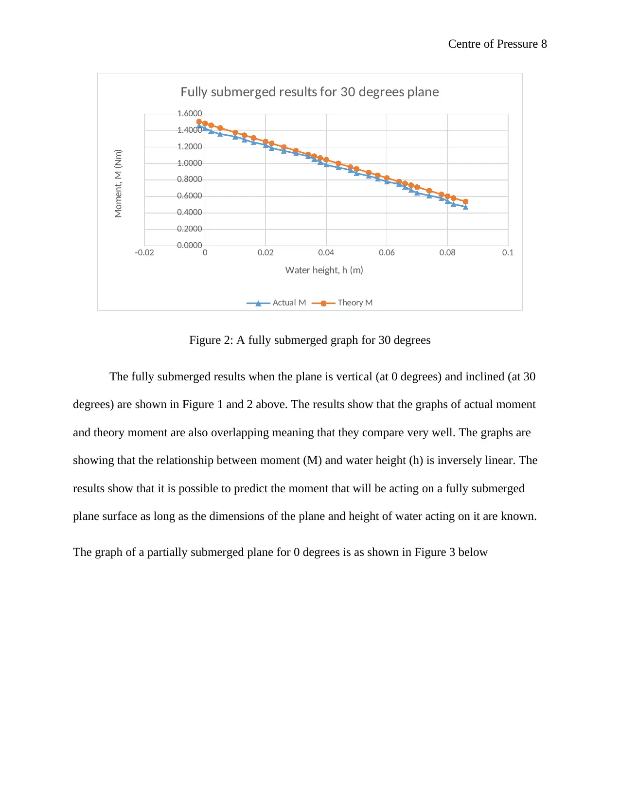
The graph of a fully submerged plane for 30 degrees is as shown in Figure 2 below
Paraphrase This Document
Need a fresh take? Get an instant paraphrase of this document with our AI Paraphraser
Centre of Pressure 8
-0.02 0 0.02 0.04 0.06 0.08 0.1
0.0000
0.2000
0.4000
0.6000
0.8000
1.0000
1.2000
1.4000
1.6000
Fully submerged results for 30 degrees plane
Actual M Theory M
Water height, h (m)
Moment, M (Nm)
Figure 2: A fully submerged graph for 30 degrees
The fully submerged results when the plane is vertical (at 0 degrees) and inclined (at 30
degrees) are shown in Figure 1 and 2 above. The results show that the graphs of actual moment
and theory moment are also overlapping meaning that they compare very well. The graphs are
showing that the relationship between moment (M) and water height (h) is inversely linear. The
results show that it is possible to predict the moment that will be acting on a fully submerged
plane surface as long as the dimensions of the plane and height of water acting on it are known.
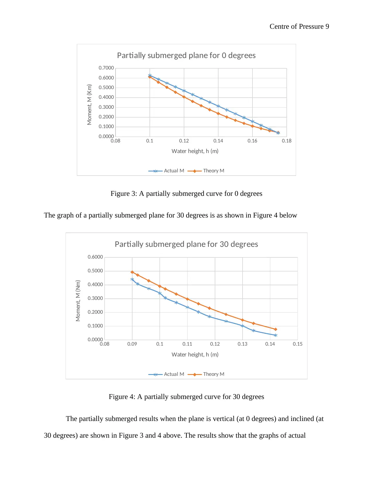
The graph of a partially submerged plane for 0 degrees is as shown in Figure 3 below
Centre of Pressure 9
0.08 0.1 0.12 0.14 0.16 0.18
0.0000
0.1000
0.2000
0.3000
0.4000
0.5000
0.6000
0.7000
Partially submerged plane for 0 degrees
Actual M Theory M
Water height, h (m)
Moment, M (Km)
Figure 3: A partially submerged curve for 0 degrees
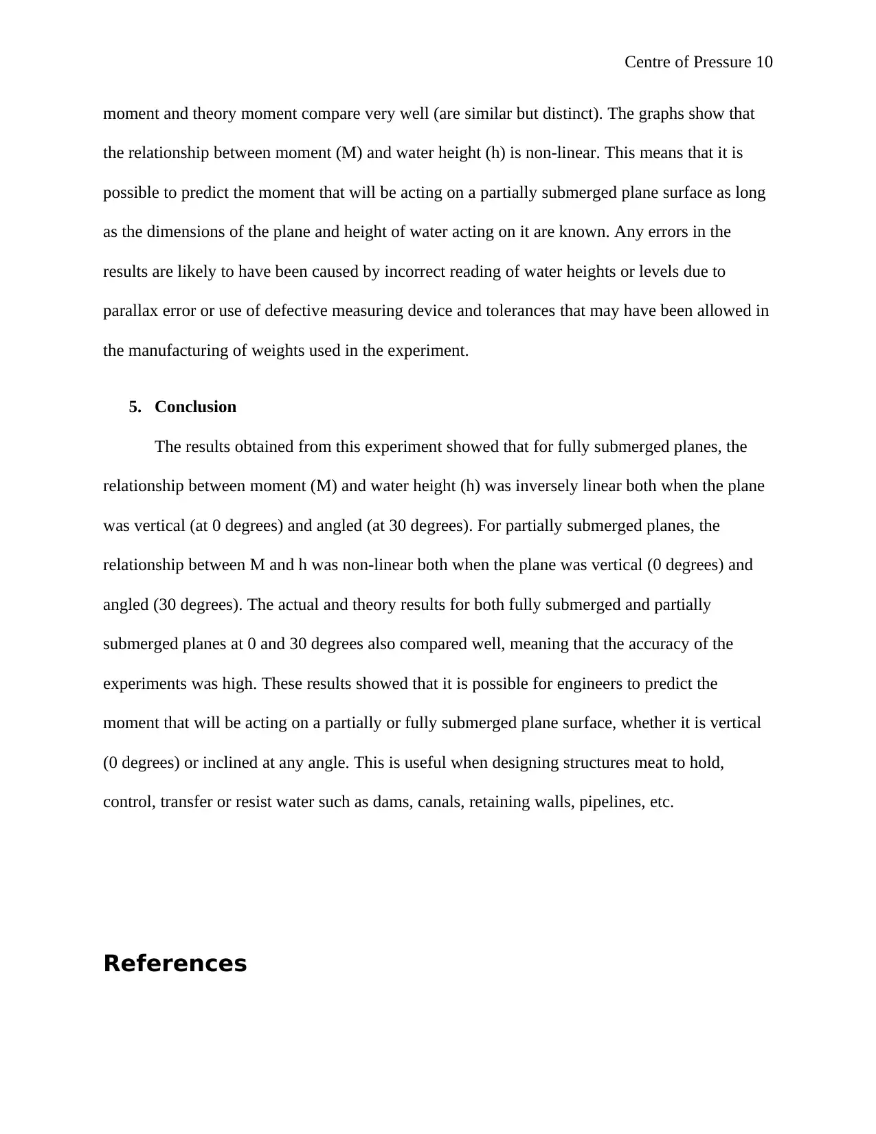
The graph of a partially submerged plane for 30 degrees is as shown in Figure 4 below
0.08 0.09 0.1 0.11 0.12 0.13 0.14 0.15
0.0000
0.1000
0.2000
0.3000
0.4000
0.5000
0.6000
Partially submerged plane for 30 degrees
Actual M Theory M
Water height, h (m)
Moment, M (Nm)
Figure 4: A partially submerged curve for 30 degrees
The partially submerged results when the plane is vertical (at 0 degrees) and inclined (at
30 degrees) are shown in Figure 3 and 4 above. The results show that the graphs of actual
⊘ This is a preview!⊘
Do you want full access?
Subscribe today to unlock all pages.

Trusted by 1+ million students worldwide
Centre of Pressure 10
moment and theory moment compare very well (are similar but distinct). The graphs show that
the relationship between moment (M) and water height (h) is non-linear. This means that it is
possible to predict the moment that will be acting on a partially submerged plane surface as long
as the dimensions of the plane and height of water acting on it are known. Any errors in the
results are likely to have been caused by incorrect reading of water heights or levels due to
parallax error or use of defective measuring device and tolerances that may have been allowed in
the manufacturing of weights used in the experiment.
5. Conclusion
The results obtained from this experiment showed that for fully submerged planes, the
relationship between moment (M) and water height (h) was inversely linear both when the plane
was vertical (at 0 degrees) and angled (at 30 degrees). For partially submerged planes, the
relationship between M and h was non-linear both when the plane was vertical (0 degrees) and
angled (30 degrees). The actual and theory results for both fully submerged and partially
submerged planes at 0 and 30 degrees also compared well, meaning that the accuracy of the
experiments was high. These results showed that it is possible for engineers to predict the
moment that will be acting on a partially or fully submerged plane surface, whether it is vertical
(0 degrees) or inclined at any angle. This is useful when designing structures meat to hold,
control, transfer or resist water such as dams, canals, retaining walls, pipelines, etc.
References
Paraphrase This Document
Need a fresh take? Get an instant paraphrase of this document with our AI Paraphraser
Centre of Pressure 11
Claydon, J., 2015. Centre of Pressure. [Online]
Available at: http://www.jfccivilengineer.com/centre_of_pressure.htm
[Accessed 22 October 2018].
Moore, J., (n.d.). Composite Parts for Moments of Inertia and the Parallel Axis Theorem. [Online]
Available at: http://adaptivemap.ma.psu.edu/websites/moment_intergrals/parallel_axis_theorem/
parallelaxistheorem.html
[Accessed 22 October 2018].
Smith, J., 2018. Parallel Axis Theorem. [Online]
Available at: https://ccrma.stanford.edu/~jos/pasp/Parallel_Axis_Theorem.html
[Accessed 22 October 2018].
TecQuipment, (n.d.). H11 Centre of Pressure Aparatus User Guide, Nottingham, UK: TecQuipment Ltd.
1 out of 11
Your All-in-One AI-Powered Toolkit for Academic Success.
+13062052269
info@desklib.com
Available 24*7 on WhatsApp / Email
![[object Object]](/_next/static/media/star-bottom.7253800d.svg)
Unlock your academic potential
Copyright © 2020–2025 A2Z Services. All Rights Reserved. Developed and managed by ZUCOL.