Rocket Nozzle CFD Analysis: Performance Evaluation and Flow Modeling
VerifiedAdded on 2023/04/25
|18
|3045
|310
Report
AI Summary
This report presents a Computational Fluid Dynamics (CFD) analysis of a convergent-divergent (de Laval) rocket nozzle using ANSYS Fluent. The study focuses on modeling the nozzle geometry, creating a high-quality mesh, and simulating the flow characteristics under isentropic conditions. The report details the theoretical background, including area-velocity relationships and equations for density, temperature, pressure, and mass flow rate. It also includes the geometry of the nozzle, meshing details using ANSYS ICEM CFD, and the setup for the CFD analysis in ANSYS Fluent, including boundary conditions and solver settings. The theoretical results section explains the behavior of converging and converging-diverging nozzles under varying back pressures, highlighting the concepts of critical pressure and shockwave formation. The project aims to provide a comprehensive understanding of rocket nozzle design and performance through CFD simulation. Desklib provides students with access to a wealth of resources, including solved assignments and past papers, to aid in their studies.
ADVANCED FLOW MODELLING INDIVIDIAL ASSIGNMENT
Topic: CFD Analysis of the Rocket Nozzle
Name of the Student
Name of the University
Author’s Note
Topic: CFD Analysis of the Rocket Nozzle
Name of the Student
Name of the University
Author’s Note
Paraphrase This Document
Need a fresh take? Get an instant paraphrase of this document with our AI Paraphraser
INTRODUCTION
A typical rocket engine consists of injectors – which delivers oxidizer and fuel to the
combustion chamber, a combustion chamber – where the fuel and oxidizer are mixed and
burned, and the nozzle – which converts the chemical and thermal energy of the gases into
the kinetic energy.
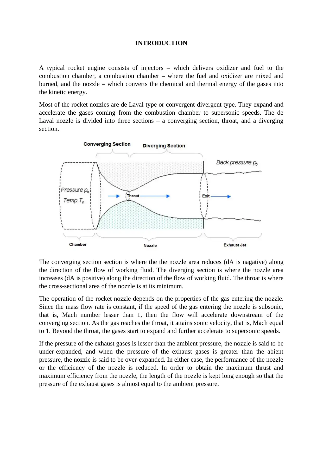
Most of the rocket nozzles are de Laval type or convergent-divergent type. They expand and
accelerate the gases coming from the combustion chamber to supersonic speeds. The de
Laval nozzle is divided into three sections – a converging section, throat, and a diverging
section.
The converging section section is where the the nozzle area reduces (dA is nagative) along
the direction of the flow of working fluid. The diverging section is where the nozzle area
increases (dA is positive) along the direction of the flow of working fluid. The throat is where
the cross-sectional area of the nozzle is at its minimum.
The operation of the rocket nozzle depends on the properties of the gas entering the nozzle.
Since the mass flow rate is constant, if the speed of the gas entering the nozzle is subsonic,
that is, Mach number lesser than 1, then the flow will accelerate downstream of the
converging section. As the gas reaches the throat, it attains sonic velocity, that is, Mach equal
to 1. Beyond the throat, the gases start to expand and further accelerate to supersonic speeds.
If the pressure of the exhaust gases is lesser than the ambient pressure, the nozzle is said to be
under-expanded, and when the pressure of the exhaust gases is greater than the abient
pressure, the nozzle is said to be over-expanded. In either case, the performance of the nozzle
or the efficiency of the nozzle is reduced. In order to obtain the maximum thrust and
maximum efficiency from the nozzle, the length of the nozzle is kept long enough so that the
pressure of the exhaust gases is almost equal to the ambient pressure.
FORMULAE
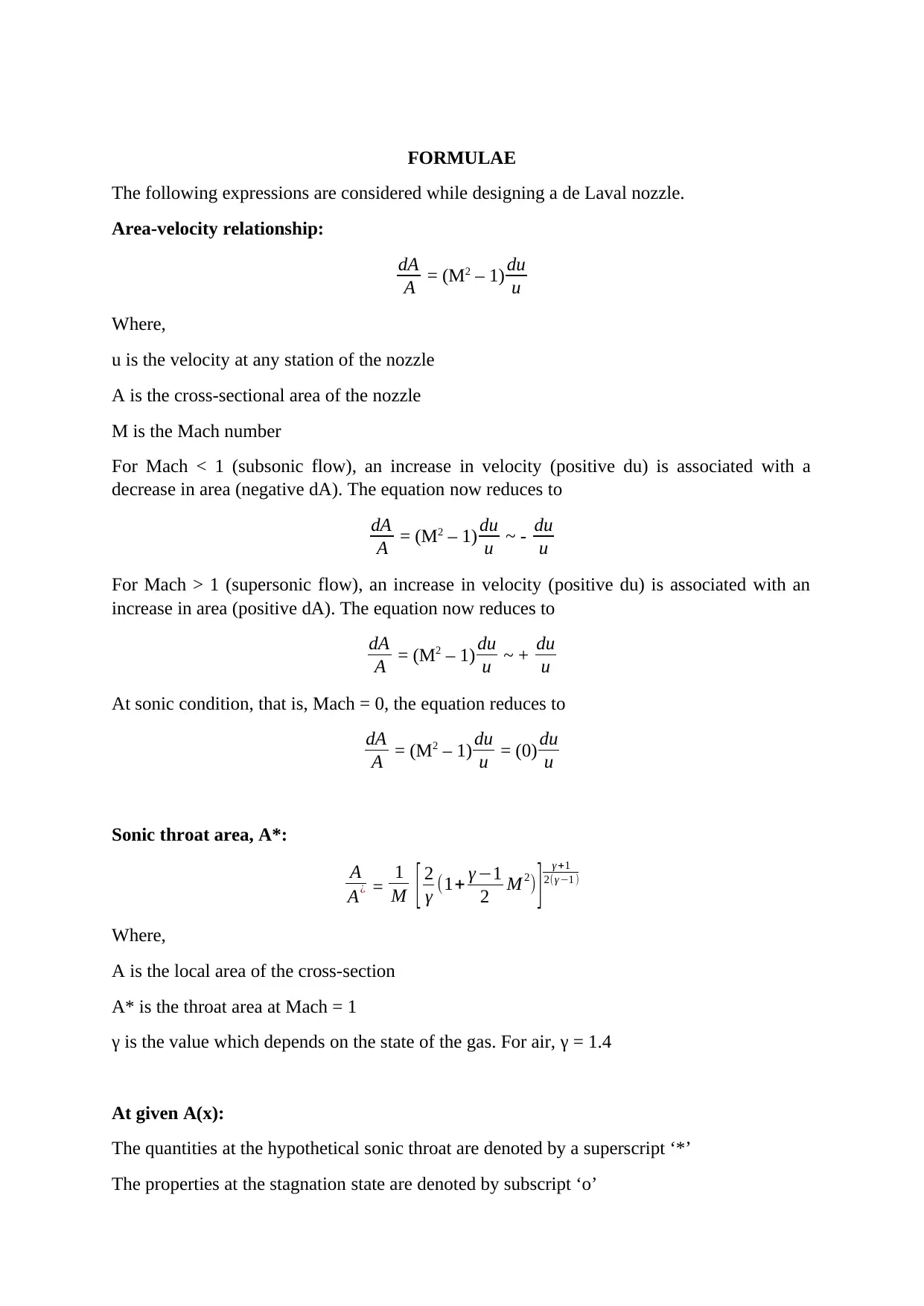
The following expressions are considered while designing a de Laval nozzle.
Area-velocity relationship:
dA
A = (M2 – 1) du
u
Where,
u is the velocity at any station of the nozzle
A is the cross-sectional area of the nozzle
M is the Mach number
For Mach < 1 (subsonic flow), an increase in velocity (positive du) is associated with a
decrease in area (negative dA). The equation now reduces to
dA
A = (M2 – 1) du
u ~ - du
u
For Mach > 1 (supersonic flow), an increase in velocity (positive du) is associated with an
increase in area (positive dA). The equation now reduces to
dA
A = (M2 – 1) du
u ~ + du
u
At sonic condition, that is, Mach = 0, the equation reduces to
dA
A = (M2 – 1) du
u = (0) du
u
Sonic throat area, A*:
A
A¿ = 1
M [ 2
γ (1+ γ −1
2 M 2) ] γ +1
2(γ −1 )
Where,
A is the local area of the cross-section
A* is the throat area at Mach = 1
γ is the value which depends on the state of the gas. For air, γ = 1.4
At given A(x):
The quantities at the hypothetical sonic throat are denoted by a superscript ‘*’
The properties at the stagnation state are denoted by subscript ‘o’
⊘ This is a preview!⊘
Do you want full access?
Subscribe today to unlock all pages.

Trusted by 1+ million students worldwide
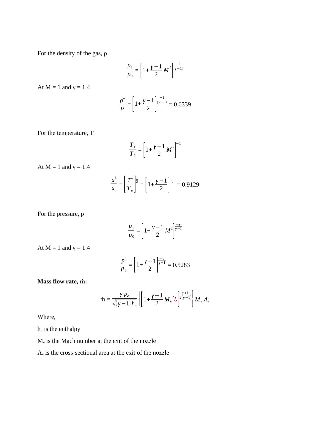
For the density of the gas, ρ
ρ1
ρ0
= [ 1+ γ −1
2 M2
] −1
(γ −1)
At M = 1 and γ = 1.4
ρ¿
ρ = [ 1+ γ −1
2 ] −1
(γ −1 ) = 0.6339
For the temperature, T
T1
T0
= [1+ γ −1
2 M 2
]−1
At M = 1 and γ = 1.4
a¿
a0
= [ T¿
T o ] 1
2
= [1+ γ −1
2 ]−1
2 = 0.9129
For the pressure, p
p1
p0
= [1+ γ −1
2 M2
] −γ
γ −1
At M = 1 and γ = 1.4
p¿
p0
= [1+ γ −1
2 ] − γ
γ−1 = 0.5283
Mass flow rate, ṁ:
ṁ = γ po
√ ( γ −1 ) ho {[1+ γ −1
2 M e
2¿ ] γ +1
2(γ −1)
} Me Ae
Where,
ho is the enthalpy
Me is the Mach number at the exit of the nozzle
Ae is the cross-sectional area at the exit of the nozzle
Paraphrase This Document
Need a fresh take? Get an instant paraphrase of this document with our AI Paraphraser
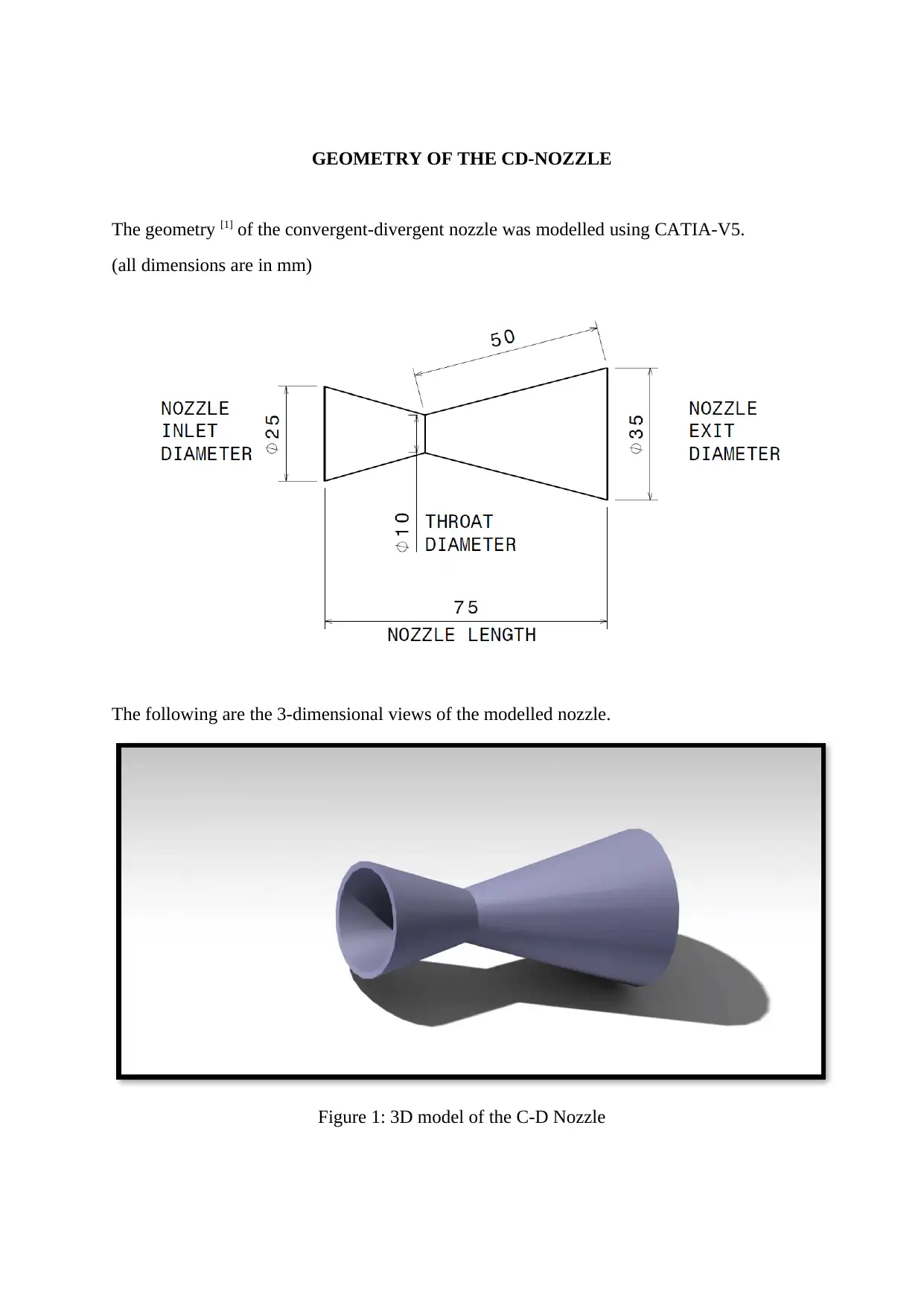
GEOMETRY OF THE CD-NOZZLE
The geometry [1] of the convergent-divergent nozzle was modelled using CATIA-V5.
(all dimensions are in mm)
The following are the 3-dimensional views of the modelled nozzle.
Figure 1: 3D model of the C-D Nozzle
The geometry [1] of the convergent-divergent nozzle was modelled using CATIA-V5.
(all dimensions are in mm)
The following are the 3-dimensional views of the modelled nozzle.
Figure 1: 3D model of the C-D Nozzle
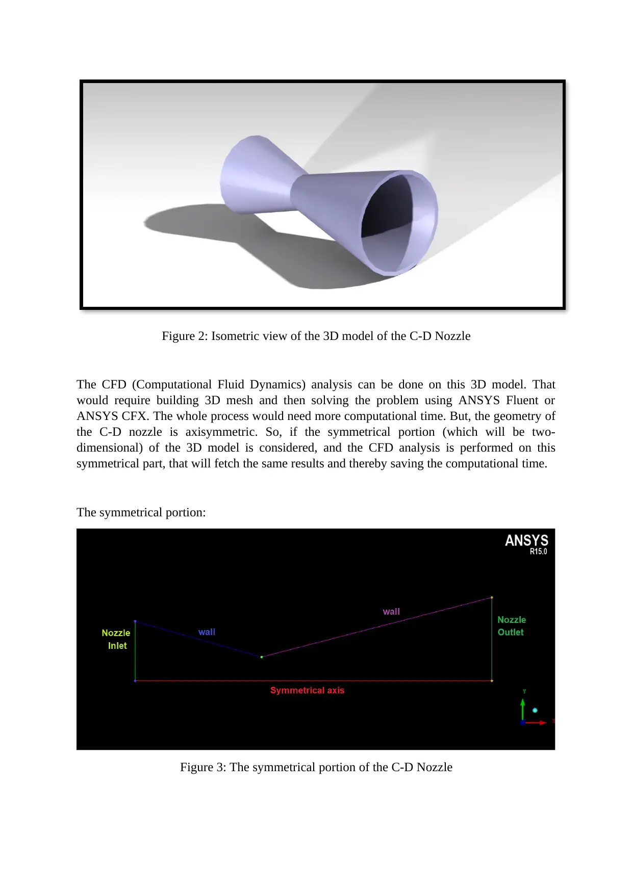
Figure 2: Isometric view of the 3D model of the C-D Nozzle
The CFD (Computational Fluid Dynamics) analysis can be done on this 3D model. That
would require building 3D mesh and then solving the problem using ANSYS Fluent or
ANSYS CFX. The whole process would need more computational time. But, the geometry of
the C-D nozzle is axisymmetric. So, if the symmetrical portion (which will be two-
dimensional) of the 3D model is considered, and the CFD analysis is performed on this
symmetrical part, that will fetch the same results and thereby saving the computational time.
The symmetrical portion:
Figure 3: The symmetrical portion of the C-D Nozzle
⊘ This is a preview!⊘
Do you want full access?
Subscribe today to unlock all pages.

Trusted by 1+ million students worldwide
MESHING OF THE CD-NOZZLE
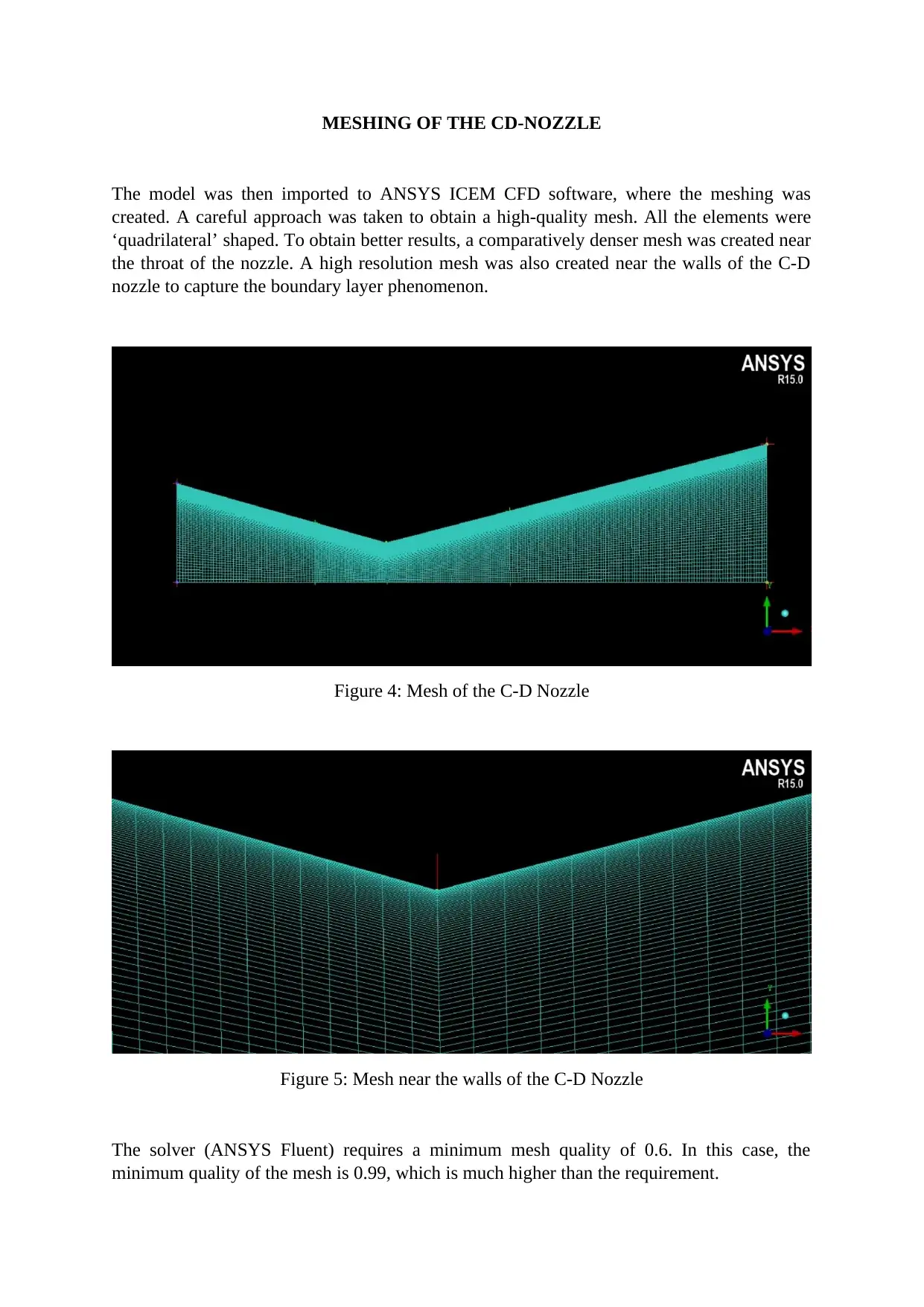
The model was then imported to ANSYS ICEM CFD software, where the meshing was
created. A careful approach was taken to obtain a high-quality mesh. All the elements were
‘quadrilateral’ shaped. To obtain better results, a comparatively denser mesh was created near
the throat of the nozzle. A high resolution mesh was also created near the walls of the C-D
nozzle to capture the boundary layer phenomenon.
Figure 4: Mesh of the C-D Nozzle
Figure 5: Mesh near the walls of the C-D Nozzle
The solver (ANSYS Fluent) requires a minimum mesh quality of 0.6. In this case, the
minimum quality of the mesh is 0.99, which is much higher than the requirement.
Paraphrase This Document
Need a fresh take? Get an instant paraphrase of this document with our AI Paraphraser
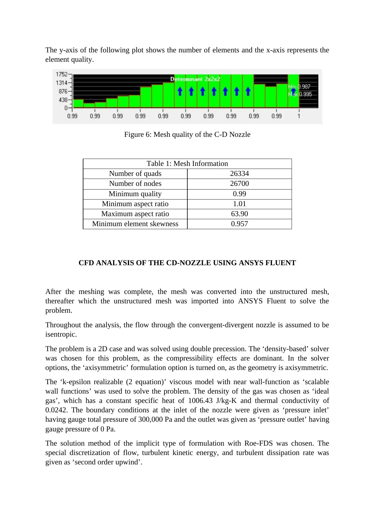
The y-axis of the following plot shows the number of elements and the x-axis represents the
element quality.
Figure 6: Mesh quality of the C-D Nozzle
Table 1: Mesh Information
Number of quads 26334
Number of nodes 26700
Minimum quality 0.99
Minimum aspect ratio 1.01
Maximum aspect ratio 63.90
Minimum element skewness 0.957
CFD ANALYSIS OF THE CD-NOZZLE USING ANSYS FLUENT
After the meshing was complete, the mesh was converted into the unstructured mesh,
thereafter which the unstructured mesh was imported into ANSYS Fluent to solve the
problem.
Throughout the analysis, the flow through the convergent-divergent nozzle is assumed to be
isentropic.
The problem is a 2D case and was solved using double precession. The ‘density-based’ solver
was chosen for this problem, as the compressibility effects are dominant. In the solver
options, the ‘axisymmetric’ formulation option is turned on, as the geometry is axisymmetric.
The ‘k-epsilon realizable (2 equation)’ viscous model with near wall-function as ‘scalable
wall functions’ was used to solve the problem. The density of the gas was chosen as ‘ideal
gas’, which has a constant specific heat of 1006.43 J/kg-K and thermal conductivity of
0.0242. The boundary conditions at the inlet of the nozzle were given as ‘pressure inlet’
having gauge total pressure of 300,000 Pa and the outlet was given as ‘pressure outlet’ having
gauge pressure of 0 Pa.
The solution method of the implicit type of formulation with Roe-FDS was chosen. The
special discretization of flow, turbulent kinetic energy, and turbulent dissipation rate was
given as ‘second order upwind’.
The absolute criteria for the residuals of continuity, x-velocity, y-velocity, energy, k, and
epsilon were chosen to be 0.000000001, that is, 1e-9, each. The solution was initialized from
‘inlet’ using the standard method of initialization.
THEORETICAL RESULTS
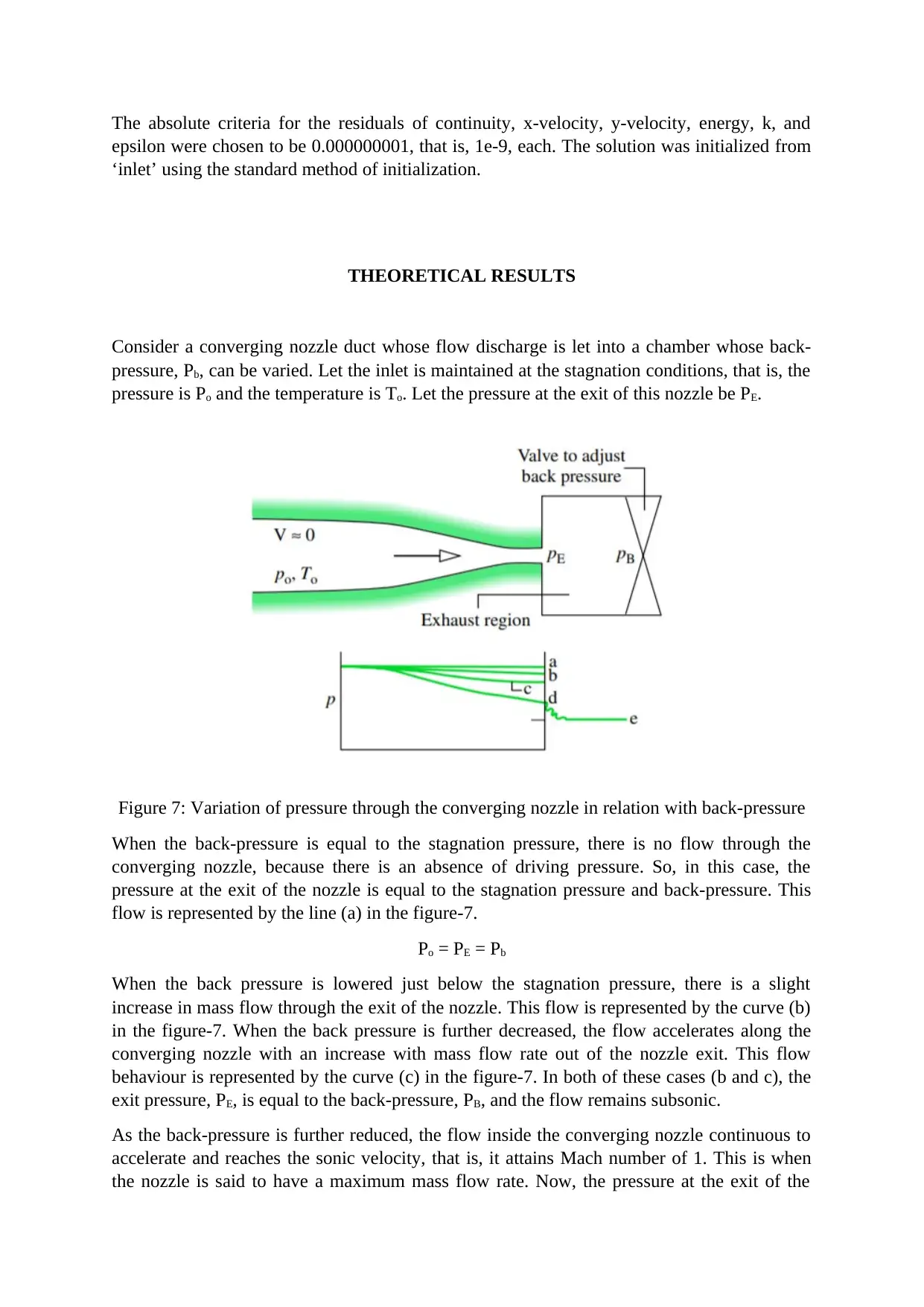
Consider a converging nozzle duct whose flow discharge is let into a chamber whose back-
pressure, Pb, can be varied. Let the inlet is maintained at the stagnation conditions, that is, the
pressure is Po and the temperature is To. Let the pressure at the exit of this nozzle be PE.
Figure 7: Variation of pressure through the converging nozzle in relation with back-pressure
When the back-pressure is equal to the stagnation pressure, there is no flow through the
converging nozzle, because there is an absence of driving pressure. So, in this case, the
pressure at the exit of the nozzle is equal to the stagnation pressure and back-pressure. This
flow is represented by the line (a) in the figure-7.
Po = PE = Pb
When the back pressure is lowered just below the stagnation pressure, there is a slight
increase in mass flow through the exit of the nozzle. This flow is represented by the curve (b)
in the figure-7. When the back pressure is further decreased, the flow accelerates along the
converging nozzle with an increase with mass flow rate out of the nozzle exit. This flow
behaviour is represented by the curve (c) in the figure-7. In both of these cases (b and c), the
exit pressure, PE, is equal to the back-pressure, PB, and the flow remains subsonic.
As the back-pressure is further reduced, the flow inside the converging nozzle continuous to
accelerate and reaches the sonic velocity, that is, it attains Mach number of 1. This is when
the nozzle is said to have a maximum mass flow rate. Now, the pressure at the exit of the
⊘ This is a preview!⊘
Do you want full access?
Subscribe today to unlock all pages.

Trusted by 1+ million students worldwide
nozzle is called as the ‘critical pressure’, which is denoted by P*. This flow behaviour is
represented by the curve (d) in the figure-7. Any further reduction in the back pressure will
have no effect in the mass flow rate through the converging nozzle.
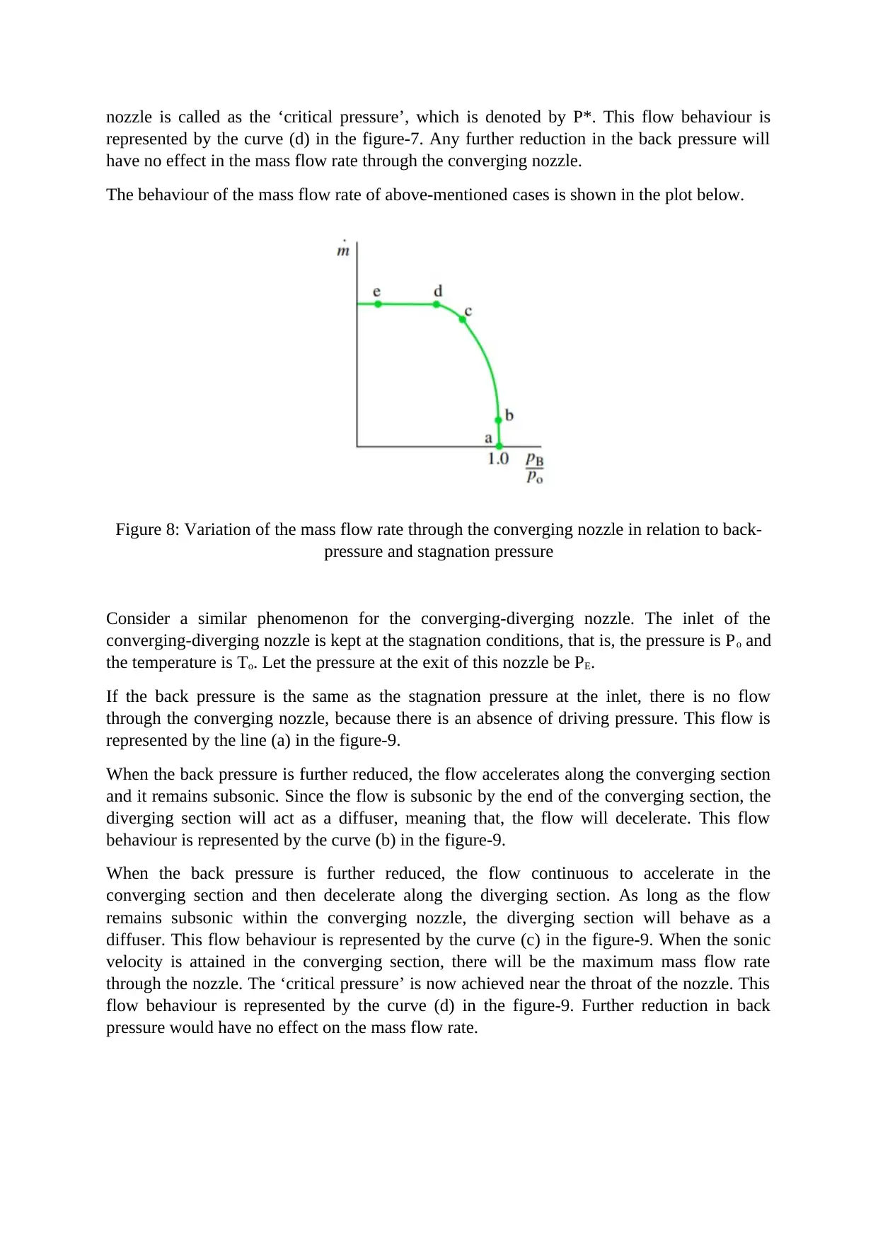
The behaviour of the mass flow rate of above-mentioned cases is shown in the plot below.
Figure 8: Variation of the mass flow rate through the converging nozzle in relation to back-
pressure and stagnation pressure
Consider a similar phenomenon for the converging-diverging nozzle. The inlet of the
converging-diverging nozzle is kept at the stagnation conditions, that is, the pressure is Po and
the temperature is To. Let the pressure at the exit of this nozzle be PE.
If the back pressure is the same as the stagnation pressure at the inlet, there is no flow
through the converging nozzle, because there is an absence of driving pressure. This flow is
represented by the line (a) in the figure-9.
When the back pressure is further reduced, the flow accelerates along the converging section
and it remains subsonic. Since the flow is subsonic by the end of the converging section, the
diverging section will act as a diffuser, meaning that, the flow will decelerate. This flow
behaviour is represented by the curve (b) in the figure-9.
When the back pressure is further reduced, the flow continuous to accelerate in the
converging section and then decelerate along the diverging section. As long as the flow
remains subsonic within the converging nozzle, the diverging section will behave as a
diffuser. This flow behaviour is represented by the curve (c) in the figure-9. When the sonic
velocity is attained in the converging section, there will be the maximum mass flow rate
through the nozzle. The ‘critical pressure’ is now achieved near the throat of the nozzle. This
flow behaviour is represented by the curve (d) in the figure-9. Further reduction in back
pressure would have no effect on the mass flow rate.
Paraphrase This Document
Need a fresh take? Get an instant paraphrase of this document with our AI Paraphraser
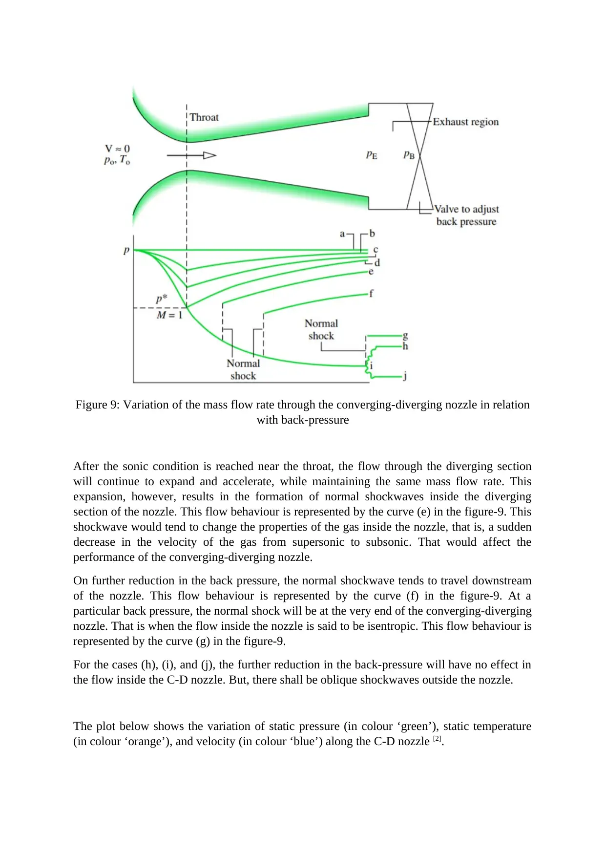
Figure 9: Variation of the mass flow rate through the converging-diverging nozzle in relation
with back-pressure
After the sonic condition is reached near the throat, the flow through the diverging section
will continue to expand and accelerate, while maintaining the same mass flow rate. This
expansion, however, results in the formation of normal shockwaves inside the diverging
section of the nozzle. This flow behaviour is represented by the curve (e) in the figure-9. This
shockwave would tend to change the properties of the gas inside the nozzle, that is, a sudden
decrease in the velocity of the gas from supersonic to subsonic. That would affect the
performance of the converging-diverging nozzle.
On further reduction in the back pressure, the normal shockwave tends to travel downstream
of the nozzle. This flow behaviour is represented by the curve (f) in the figure-9. At a
particular back pressure, the normal shock will be at the very end of the converging-diverging
nozzle. That is when the flow inside the nozzle is said to be isentropic. This flow behaviour is
represented by the curve (g) in the figure-9.
For the cases (h), (i), and (j), the further reduction in the back-pressure will have no effect in
the flow inside the C-D nozzle. But, there shall be oblique shockwaves outside the nozzle.
The plot below shows the variation of static pressure (in colour ‘green’), static temperature
(in colour ‘orange’), and velocity (in colour ‘blue’) along the C-D nozzle [2].
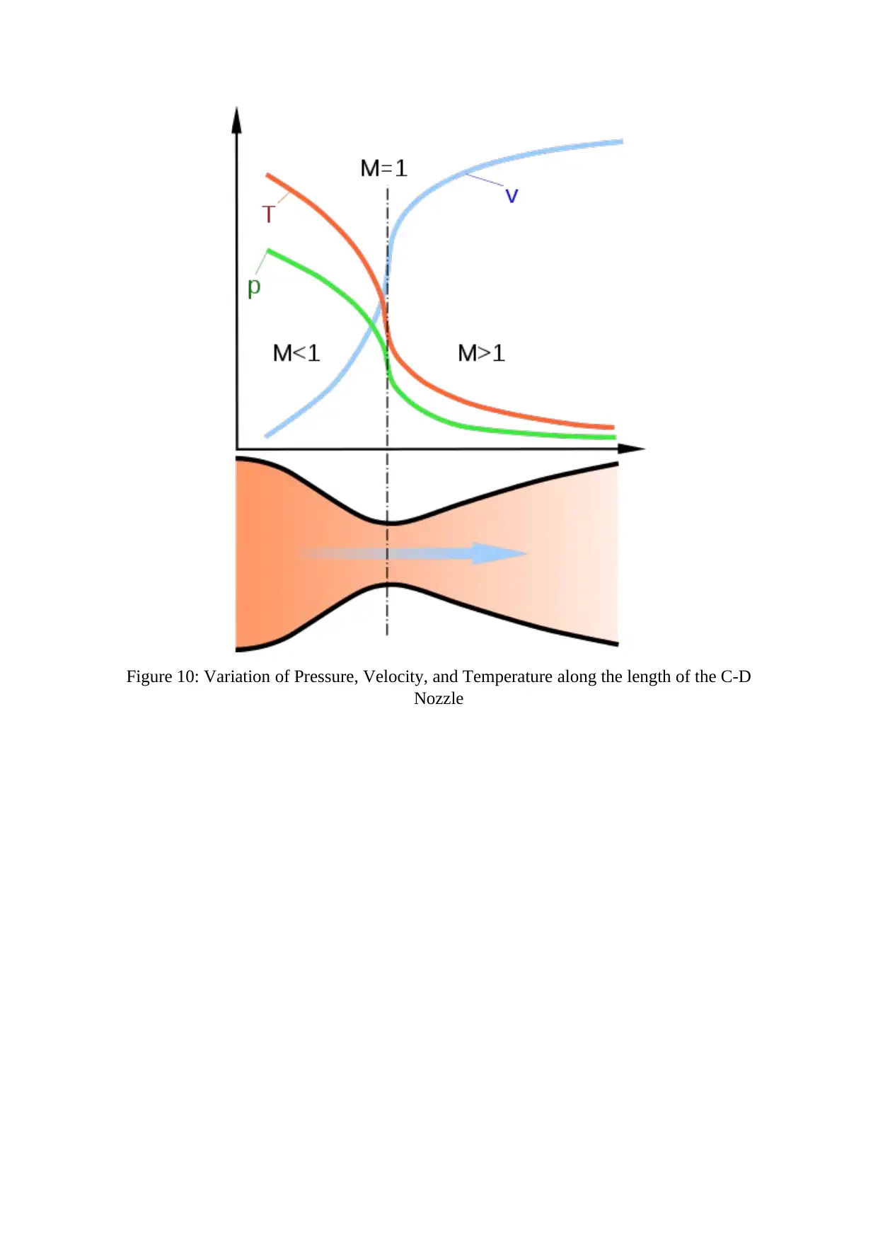
Figure 10: Variation of Pressure, Velocity, and Temperature along the length of the C-D
Nozzle
Nozzle
⊘ This is a preview!⊘
Do you want full access?
Subscribe today to unlock all pages.

Trusted by 1+ million students worldwide
1 out of 18
Related Documents
Your All-in-One AI-Powered Toolkit for Academic Success.
+13062052269
info@desklib.com
Available 24*7 on WhatsApp / Email
![[object Object]](/_next/static/media/star-bottom.7253800d.svg)
Unlock your academic potential
Copyright © 2020–2025 A2Z Services. All Rights Reserved. Developed and managed by ZUCOL.


