CFD Analysis Report: Fluid Dynamics, Pipe Flow Simulation, ANSYS

Verified

Added on  2023/06/13

|13
|1951
|342
Report
AI Summary
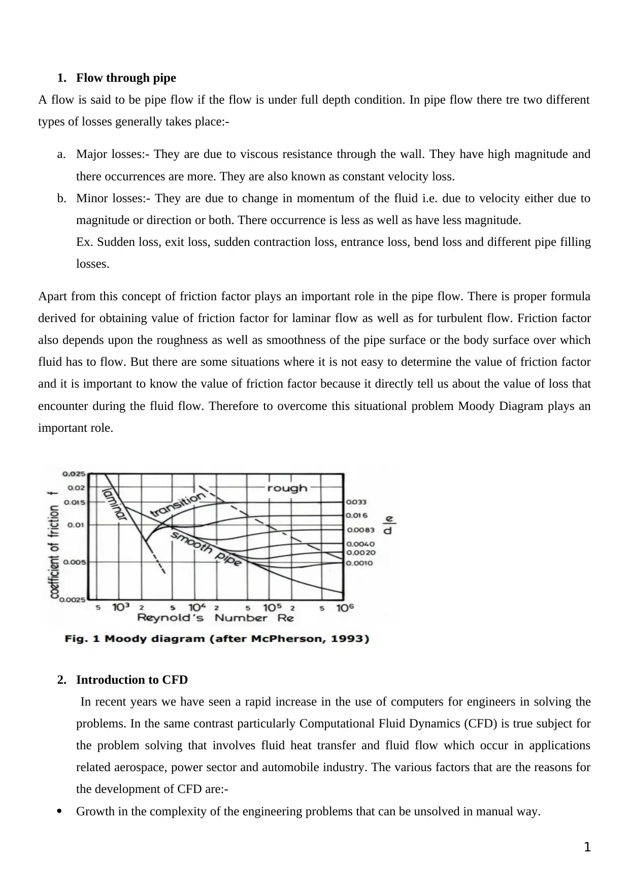
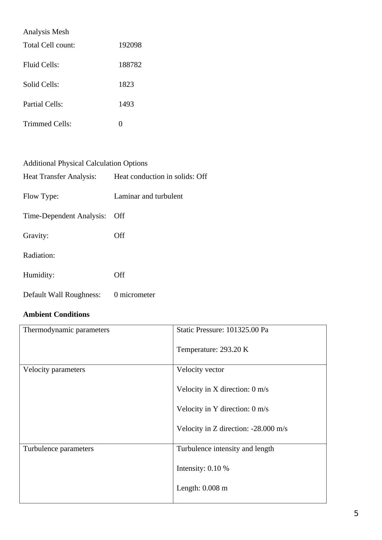
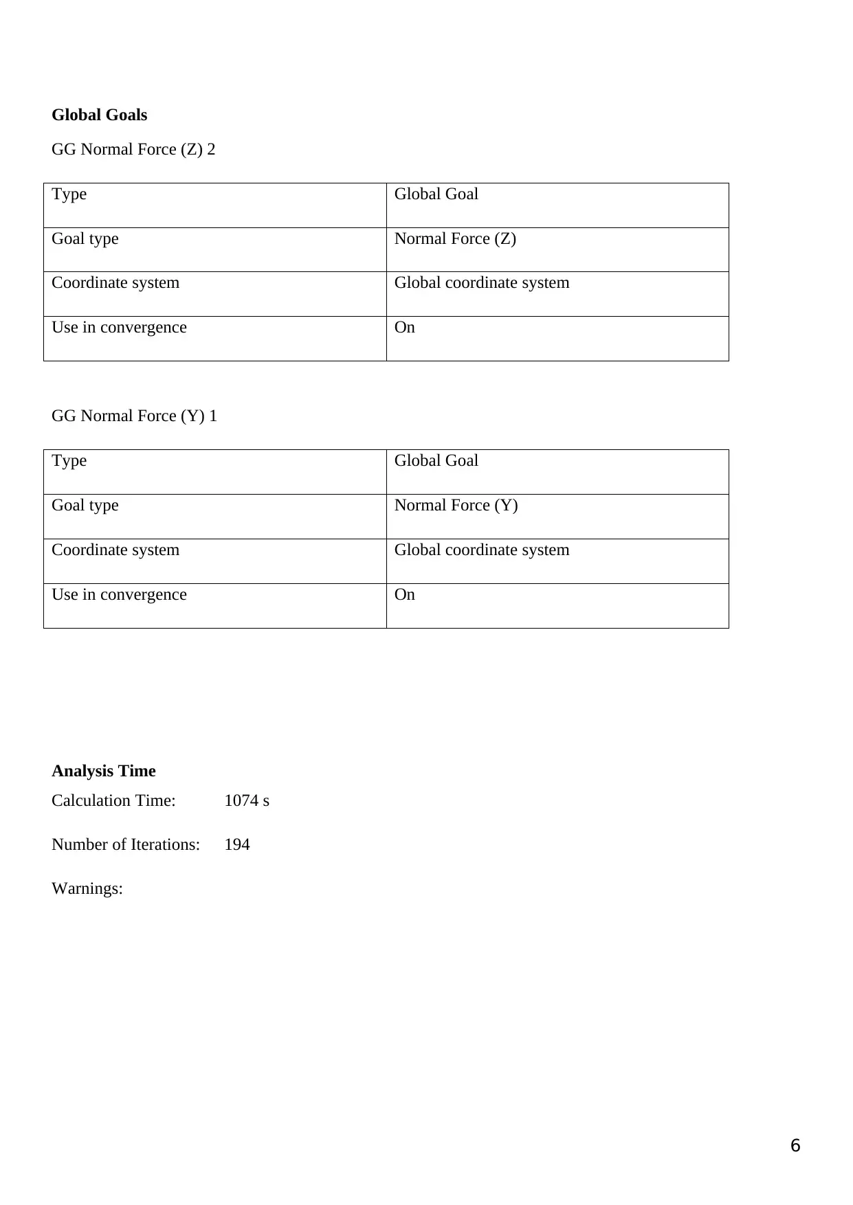
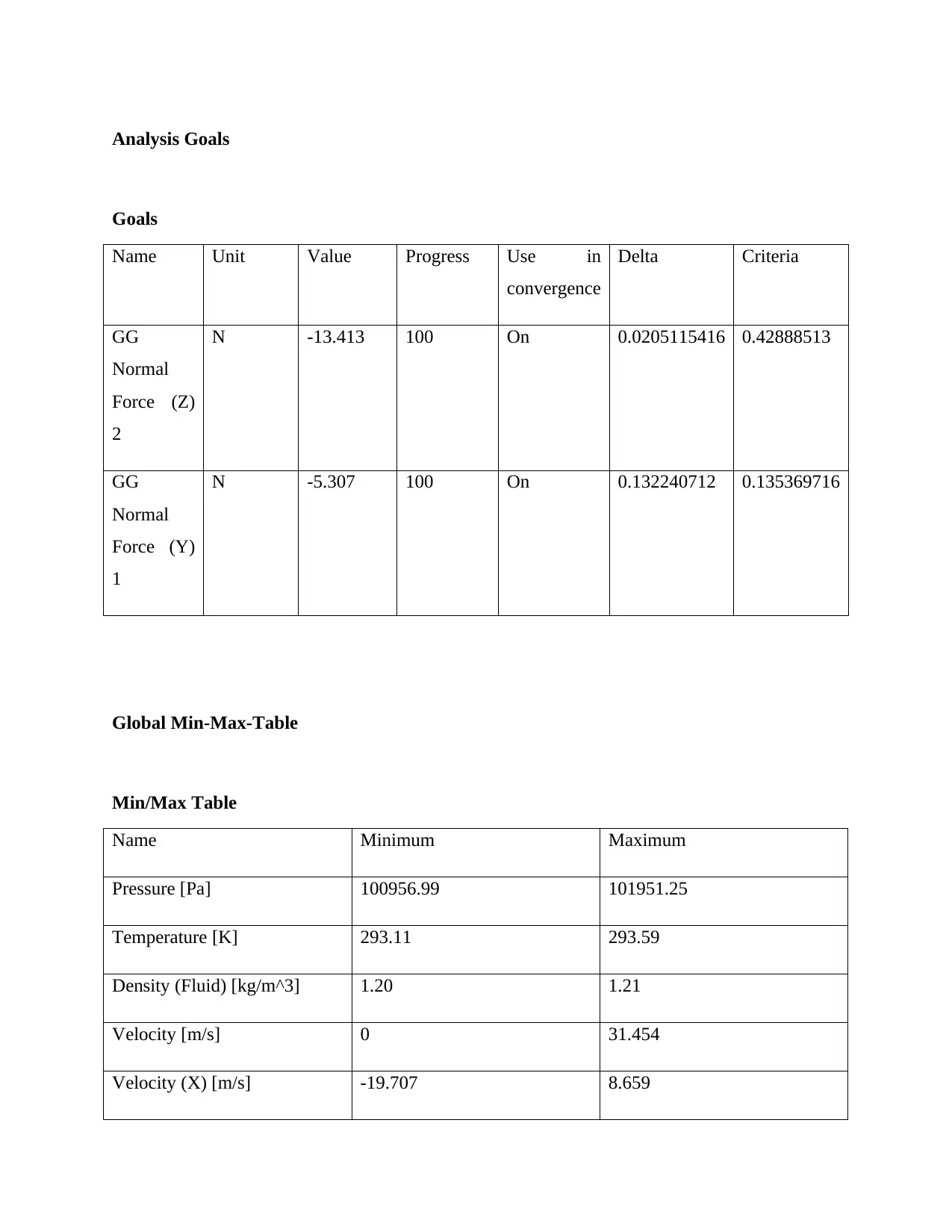
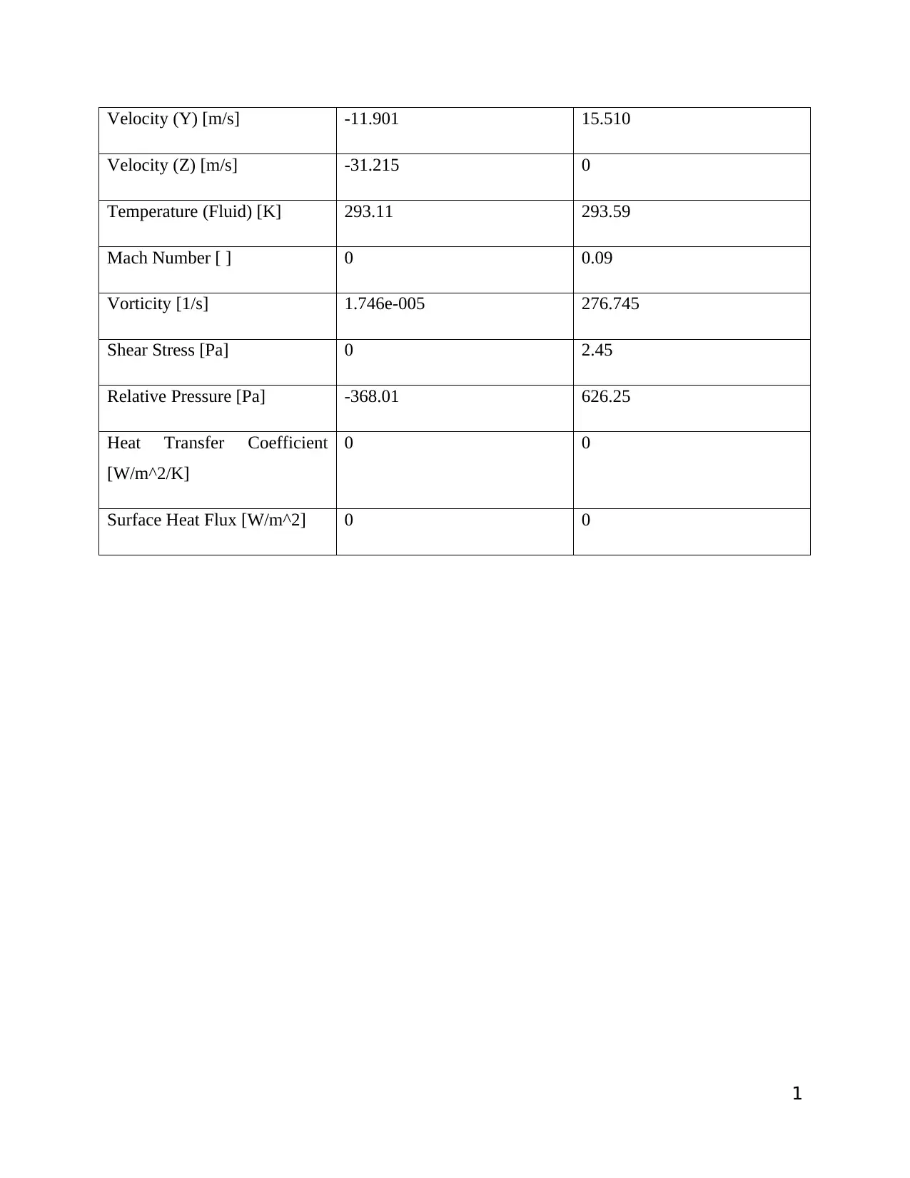
This report presents a Computational Fluid Dynamics (CFD) analysis focusing on fluid dynamics and flow through pipes. It begins with an overview of pipe flow, differentiating between major and minor losses, and introduces the concept of friction factor and Moody Diagram. The report then transitions into an introduction to CFD, highlighting its increasing importance in solving complex engineering problems related to fluid flow and heat transfer, especially in aerospace, power, and automobile industries. It elaborates on the governing equations of fluid dynamics—continuity, momentum, and energy equations—and their application in ANSYS analysis for aerodynamic design. Key concepts like flow lines (streamline, path line, streak line), acceleration in fluid motion, contours, circulation, and vorticity are defined. The analysis environment, software product (Flow Simulation 2014), and simulation parameters, including mesh settings, physical calculation options, and global goals, are detailed. The report concludes with the advantages and disadvantages of CFD, its future prospects, and references to relevant studies.
Document Page
CFD
[Document subtitle]
APRIL 22, 2018
HP
[Company address]
tabler-icon-diamond-filled.svg

Secure Best Marks with AI Grader

Need help grading? Try our AI Grader for instant feedback on your assignments.
Document Page
Table of Contents
1. Flow through pipes.
2. Introduction to CFD.
3. Introduction of CFD in fluid dynamics.
4. Advantages of CFD
5. Disadvantages of CFD
6. Future of CFD
I
Document Page
1. Flow through pipe
A flow is said to be pipe flow if the flow is under full depth condition. In pipe flow there tre two different
types of losses generally takes place:-
a. Major losses:- They are due to viscous resistance through the wall. They have high magnitude and
there occurrences are more. They are also known as constant velocity loss.
b. Minor losses:- They are due to change in momentum of the fluid i.e. due to velocity either due to
magnitude or direction or both. There occurrence is less as well as have less magnitude.
Ex. Sudden loss, exit loss, sudden contraction loss, entrance loss, bend loss and different pipe filling
losses.
Apart from this concept of friction factor plays an important role in the pipe flow. There is proper formula
derived for obtaining value of friction factor for laminar flow as well as for turbulent flow. Friction factor
also depends upon the roughness as well as smoothness of the pipe surface or the body surface over which
fluid has to flow. But there are some situations where it is not easy to determine the value of friction factor
and it is important to know the value of friction factor because it directly tell us about the value of loss that
encounter during the fluid flow. Therefore to overcome this situational problem Moody Diagram plays an
important role.
2. Introduction to CFD
In recent years we have seen a rapid increase in the use of computers for engineers in solving the
problems. In the same contrast particularly Computational Fluid Dynamics (CFD) is true subject for
the problem solving that involves fluid heat transfer and fluid flow which occur in applications
related aerospace, power sector and automobile industry. The various factors that are the reasons for
the development of CFD are:-
Growth in the complexity of the engineering problems that can be unsolved in manual way.
1
Document Page
Need of quick solution with moderate accuracy.
The expenses that an industry bears during laboratory experiment of physical prototype.
The absence of analytical solutions.
Exponential growth in the number crunching abilities and rigorous computer speed and its
CFD enables us to utilize its tools more in day today automobile and aircraft design and also helps in solving
the fluid flow problems.. CFD applications in the any industries have large number of codes available for
designing of any product. There are several applications ranging from system - level (e.g., exterior
aerodynamics) to the components - level (e.g., disk brake cooling).
3. Introduction of CFD in fluid dynamics
Study of motion of the fluid with reference of forces and moments is known as fluid dynamics. In fluid flow
there different types of forces occurs in the flow like viscous forces, gravitational forces, pressure forces,
surface tension forces, eddy forces (turbulent forces) and different type of other forces.
All CFD in one form is based on governing equations of fluid dynamics- the continuity equation,
momentum equations and energy equations.
Conservation of mass.
Newton’s second law i.e. F=ma.
Conservation of energy.
In fluid flow velocity is function of space and time, so the acceleration is the function of space and
time. Space component is known as convective acceleration and time component is known as local
acceleration. During the ANSYS analysis the above acceleration place an important role and help the
engineer to make proper aerodynamic design of the vehicle. This is so because the acceleration and
velocity component are responsible for lift and drag of the vehicle. Improper design leads to create
serious lift of vehicle and this may results in serious accident. Inorder to avoid this impact in the
absence of physical prototype graphically the prototype is designed and is tested through computer
itself by the use of ANSYS and employing Computational Fluid Dynamics theory.
Apart from the above concept some terms need to be described which will helps to validate the whole
analysis:-
1. Flow Lines:- Fluid flow can be described by 3 flow lines
Stream line:- It is an imaginary line or curve drawn in space such that tangent drawn gives
velocity vector i.e. velocity vector and stream line vector coincides. The two streamlines
never intersect each other as well as stream line also never intersects itself because at the
point of intersection there will be two velocity fields which is impossible. So there is no flow
across the streamlines.
2
tabler-icon-diamond-filled.svg

Secure Best Marks with AI Grader

Need help grading? Try our AI Grader for instant feedback on your assignments.
Document Page
Path line:- The line drawn by tracing the path of single fluid particle at different time
integrals. It is defined on the basis of ‘Langrangian description’.
Streak line:- It is an instantaneous picture of all fluid particles passing through single point.
NOTE:- For the steady flow all three lines are identical i.e. all three line coincides.
2. Acceleration in fluid motion:- In fluid flow velocity is the function of space and time, so the
acceleration is the function of space and time. Space component is known as convective acceleration
and time component is known as Local acceleration.
3. Contours:- It is an outline representing or bounding the shape or form of something. It is used for
representation of typical response system in other words we can say it is typical curve line which
describes the response system.
4. Circulation:- It is the line integration of tangential component of velocity along the closed loop. It is
the scalar quantity.
5. Vorticity:- It is the mathematical measure of rationality. It is circulation per unit area. It is wise of the
rotation. The direction of vorticity is as that of rotation.
Analysis Environment
Software Product: Flow Simulation 2014 SP1.0. Build: 2573
CPU Type: Intel(R) Core(TM) i3-3110M CPU @ 2.40GHz
CPU Speed: 2400 MHz
RAM: 3994 MB / 134217727 MB
Operating System: (Build 9600)
Model Information
Model Name: INTF_GREEN-1.sldprt
Project Name: car_cfd(2)
3
Document Page
Project Comments:
Unit System: SI (m-kg-s)
Analysis Type: External (exclude internal spaces)
Size of Computational Domain
Size
X min -2.084 m
X max 1.119 m
Y min -1.322 m
Y max 2.180 m
Z min -7.312 m
Z max 2.318 m
Simulation Parameters
Mesh Settings
Basic Mesh
Basic Mesh Dimensions
Number of cells in X 30
Number of cells in Y 50
Number of cells in Z 128
4
Document Page
Analysis Mesh
Total Cell count: 192098
Fluid Cells: 188782
Solid Cells: 1823
Partial Cells: 1493
Trimmed Cells: 0
Additional Physical Calculation Options
Heat Transfer Analysis: Heat conduction in solids: Off
Flow Type: Laminar and turbulent
Time-Dependent Analysis: Off
Gravity: Off
Radiation:
Humidity: Off
Default Wall Roughness: 0 micrometer
Ambient Conditions
Thermodynamic parameters Static Pressure: 101325.00 Pa
Temperature: 293.20 K
Velocity parameters Velocity vector
Velocity in X direction: 0 m/s
Velocity in Y direction: 0 m/s
Velocity in Z direction: -28.000 m/s
Turbulence parameters Turbulence intensity and length
Intensity: 0.10 %
Length: 0.008 m
5
tabler-icon-diamond-filled.svg

Paraphrase This Document

Need a fresh take? Get an instant paraphrase of this document with our AI Paraphraser
Document Page
Global Goals
GG Normal Force (Z) 2
Type Global Goal
Goal type Normal Force (Z)
Coordinate system Global coordinate system
Use in convergence On
GG Normal Force (Y) 1
Type Global Goal
Goal type Normal Force (Y)
Coordinate system Global coordinate system
Use in convergence On
Analysis Time
Calculation Time: 1074 s
Number of Iterations: 194
Warnings:
6
Document Page
Analysis Goals
Goals
Name Unit Value Progress Use in
convergence
Delta Criteria
GG
Normal
Force (Z)
2
N -13.413 100 On 0.0205115416 0.42888513
GG
Normal
Force (Y)
1
N -5.307 100 On 0.132240712 0.135369716
Global Min-Max-Table
Min/Max Table
Name Minimum Maximum
Pressure [Pa] 100956.99 101951.25
Temperature [K] 293.11 293.59
Density (Fluid) [kg/m^3] 1.20 1.21
Velocity [m/s] 0 31.454
Velocity (X) [m/s] -19.707 8.659
Document Page
Velocity (Y) [m/s] -11.901 15.510
Velocity (Z) [m/s] -31.215 0
Temperature (Fluid) [K] 293.11 293.59
Mach Number [ ] 0 0.09
Vorticity [1/s] 1.746e-005 276.745
Shear Stress [Pa] 0 2.45
Relative Pressure [Pa] -368.01 626.25
Heat Transfer Coefficient
[W/m^2/K]
0 0
Surface Heat Flux [W/m^2] 0 0
1
tabler-icon-diamond-filled.svg

Secure Best Marks with AI Grader

Need help grading? Try our AI Grader for instant feedback on your assignments.
Document Page
Figure 1. Iso View of Wireframe
2
Inlet
Outlet
Document Page
4. Advantages of CFD
1. It finds a critical broken process and offers a solution.
2. It involves simplified equations and simulations.
3. Provides better prediction in a short time period.
5. Disadvantages of CFD
1. Initial investment cost is high.
2. Required skilled persons therefore costly in field of professionals.
3
Direction of Fluid
Document Page
6. Future of CFD
After the above analysis we have reached a certain platform in understanding of and appreciation
for CFD. CFD is the new “third dimension” in fluid dynamics, equally sharing the stage with the
other dimension of pure theory and pure experiment. Throug CFD we come to know about the
nature of fluid flow through the pipes and the most important is the understanding of flow over
the aerofoils.
References:-
References
There are no sources in the current document.
1. Automotive computational fluid dynamics simulation of a car using ANSYS. Praveen
Padagannavar and Manohara Bheemanna School of Aerospace, Mechanical &
Manufacturing Engineering Royal Melbourne Institute of Technology (RMIT University)
Melbourne, VIC 3001, Australia
2. Janvijay Pateriya, Raj Kumar Yadav, Vikas Mukhraiya and Pankaj Singh, Brake Disc
Analysis with the Help of Ansys Software. International Journal of Mechanical
Engineering and Technology, 6(11), 2015, pp. 114–122.
3. Rakesh Jaiswal, Anupam Raj Jha, Anush Karki, Debayan Das, Pawan Jaiswal, Saurav
Rajgadia, Ankit Basnet and Rabindra Nath Barman, Structural and Thermal Analysis of
Disc Brake Using Solidworks and Ansys. International Journal of Mechanical
Engineering and Technology, 7(1), 2016, pp. 67–77.
4. J.Ducoste, ‘An Overview of Computational Fluid Dynamics’, 2008
5. Mampeay, F., and Z. A.Xu “An experimental and simulation Study of mold filling
combined with heat transfer”. In C. Hirsch, J, Periaux and W. Kordulla(eds.),
Computational Fluid dynamics ’92, vol. 1, Elsevier, Amsterdam,1992,pp. 421-428.
4
chevron_up_icon
1 out of 13
circle_padding
hide_on_mobile
zoom_out_icon
logo.png

Your All-in-One AI-Powered Toolkit for Academic Success.

Available 24*7 on WhatsApp / Email

[object Object]