Ask a question from expert
Assignment on Hydrocarbons
22 Pages6063 Words360 Views
Added on 2019-10-18
Assignment on Hydrocarbons
Added on 2019-10-18
BookmarkShareRelated Documents
CHAPTER ONE1.0BackgroundHydrocarbons which are produced from wells whether oil or gas are not in the form of simple mixtures but of very complexform of liquid or gas mixture of hundreds of different composites of chemically bonded compounds. A well stream typicallyis turbulent of mixed substances such as gas, oil, water including minerals of dissolved form containing a substantialamount of salt, corrosive gasses such as Carbon dioxide (CO2) and Hydrogen sulfide (H2S), and different solids e.g. sands ofunconsolidated forms producing intervals on a reservoir from which particles of sands may become detached at theslightest flow rate of production. Therefore, the need for separation processes to align these components to their exportstandards and bring about the flow of branched-out but simultaneous components is carried out by the separator. Nonetheless, the types of separators used in the oil and gas industry are three which vary in terms of both form andfunction such as Horizontal separator, vertical separator and spherical separator. The Horizontal type can be subdividedinto even further sections such as single tube and double tubes. Both horizontal and vertical separators may be classed astwo phase and or three phase separators, this depends on their specifications and purposes. Depending on the objectivetargeted, a two phase separator will be used for the separation of a two phase only (oil-gas) or (gas-water) separation and athree phase separator is used for the separation of a gas from water and gas equally. Among the entire field processingoperations, the separation of a gas from free-liquid has shown to be the most critical stage. The desired size of a particularseparation unit is equally (directly) proportional to that of a composition of fluid mixture and pressure. Hence, this projectaims to demonstrate for the design of a three-phase horizontal separator, whilst considering factors that influences thedesign of a separator including; oil and gas capacity constraints, bending moments and stress, design materials, cost fordesign amongst others. However, Guo, B. et al, (2007) argues that separators function on the basis of gravity segregation/settling or centrifugalsegregation. The separator construction normally depends on the: Inlet device, where the primary separation of gas-liquid bulk occurs.A large settling section of adequate height or length to allow for liquid droplets.Equipped with a mist extractor near the gas outlet to coalesce any entrained liquid droplets that do not settle dueto gravity.adequate controls, such as: liquid level controller, placed between oil-water level and in the oil section, liquiddump valves, gas back-pressure valve, pressure gauges, instrument gas regulator and piping.
2

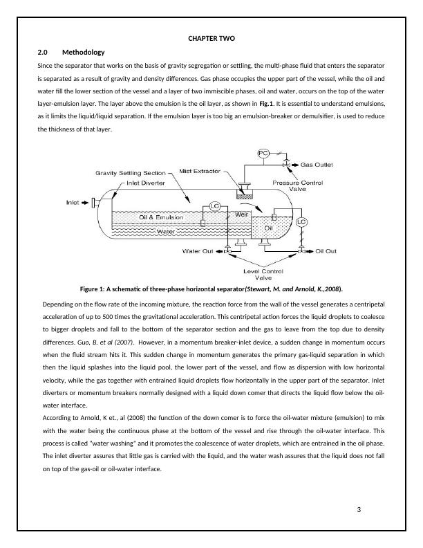
CHAPTER TWO2.0MethodologySince the separator that works on the basis of gravity segregation or settling, the multi-phase fluid that enters the separatoris separated as a result of gravity and density differences. Gas phase occupies the upper part of the vessel, while the oil andwater fill the lower section of the vessel and a layer of two immiscible phases, oil and water, occurs on the top of the waterlayer-emulsion layer. The layer above the emulsion is the oil layer, as shown in Fig.1. It is essential to understand emulsions,as it limits the liquid/liquid separation. If the emulsion layer is too big an emulsion-breaker or demulsifier, is used to reducethe thickness of that layer.Figure 1: A schematic of three-phase horizontal separator(Stewart, M. and Arnold, K.,2008).Depending on the flow rate of the incoming mixture, the reaction force from the wall of the vessel generates a centripetalacceleration of up to 500 times the gravitational acceleration. This centripetal action forces the liquid droplets to coalesceto bigger droplets and fall to the bottom of the separator section and the gas to leave from the top due to densitydifferences. Guo, B. et al (2007). However, in a momentum breaker-inlet device, a sudden change in momentum occurswhen the fluid stream hits it. This sudden change in momentum generates the primary gas-liquid separation in whichthen the liquid splashes into the liquid pool, the lower part of the vessel, and flow as dispersion with low horizontalvelocity, while the gas together with entrained liquid droplets flow horizontally in the upper part of the separator. Inletdiverters or momentum breakers normally designed with a liquid down comer that directs the liquid flow below the oil-water interface.According to Arnold, K et., al (2008) the function of the down comer is to force the oil-water mixture (emulsion) to mixwith the water being the continuous phase at the bottom of the vessel and rise through the oil-water interface. Thisprocess is called “water washing” and it promotes the coalescence of water droplets, which are entrained in the oil phase.The inlet diverter assures that little gas is carried with the liquid, and the water wash assures that the liquid does not fallon top of the gas-oil or oil-water interface.3Weir
2.1Factors Affecting Separation ProcessesThere are some factors that affect the separation efficiency in a separator. The following factors must be determinedbefore separation design:Flow Rate of Gas and liquid.Operating and design pressures and temperaturePhysical properties of the fluid such as , Z, , Sg, etc.,Surging or slugging tendencies of feed streams.Size of droplet to be removed.Presence of impurities e.g: Paraffin, sand, scale, etc.,Foaming tendencies of the crude oil,Corrosive tendencies of the liquid or gas.Arnold, K. 2007, reported challenges associated with separation processes such as:Foaming: Pressure reduction in certain types of crude oils may produce foaming. It occurs when small bubbles of gases that are dissolved in the oil start to come out of solution, and are incased in a thin film of oil.Emulsion: Materials become emulsified due to the presence of oil and water at the same time. The liquid/liquidseparation will be limited, if a large emulsion layer exists.Corrosion: Produced well fluids can be very corrosive and may cause the primary failure of process equipment. Thetwo most corrosive elements are hydrogen sulfide and carbon dioxide. These two gases may present in the well fluids inquantities from a race up to 40% to 50% of the gas by volume.Paraffin: The deposition of paraffin in separators could reduce their efficiency through the build-up action insidethe vessel. Paraffin build-up may block the fluid passages and the mist extractor, and consequently leads to costlyoperation shut downs.Sand: When dealing with separators, sand could have a worrying effect; as it is capable of causing metal erosion,especially in valves and chocks. In addition, it can accumulate at the bottom of the separator leading to blockage orclogging of the separator internals.4
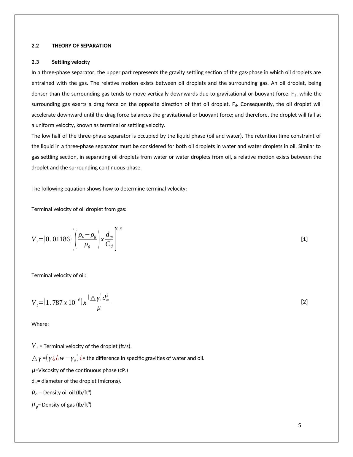
2.2THEORY OF SEPARATION2.3Settling velocityIn a three-phase separator, the upper part represents the gravity settling section of the gas-phase in which oil droplets areentrained with the gas. The relative motion exists between oil droplets and the surrounding gas. An oil droplet, beingdenser than the surrounding gas tends to move vertically downwards due to gravitational or buoyant force, Fg, while thesurrounding gas exerts a drag force on the opposite direction of that oil droplet, Fd. Consequently, the oil droplet willaccelerate downward until the drag force balances the gravitational or buoyant force; and therefore, the droplet will fall ata uniform velocity, known as terminal or settling velocity.The low half of the three-phase separator is occupied by the liquid phase (oil and water). The retention time constraint ofthe liquid in a three-phase separator must be considered for both oil droplets in water and water droplets in oil. Similar togas settling section, in separating oil droplets from water or water droplets from oil, a relative motion exists between thedroplet and the surrounding continuous phase. The following equation shows how to determine terminal velocity:Terminal velocity of oil droplet from gas:Vt=(0.01186)[(ρo−ρgρg)xdmCd]0.5[1]Terminal velocity of oil:Vt=(1.787x10⁻⁶)x(△γ)dm2μ[2]Where:Vt = Terminal velocity of the droplet (ft/s).△γ =(γ¿¿w−γo)¿= the difference in specific gravities of water and oil.μ=Viscosity of the continuous phase (cP.)dm= diameter of the droplet (microns).ρo = Density oil oil (Ib/ft3)ρg= Density of gas (Ib/ft3)5
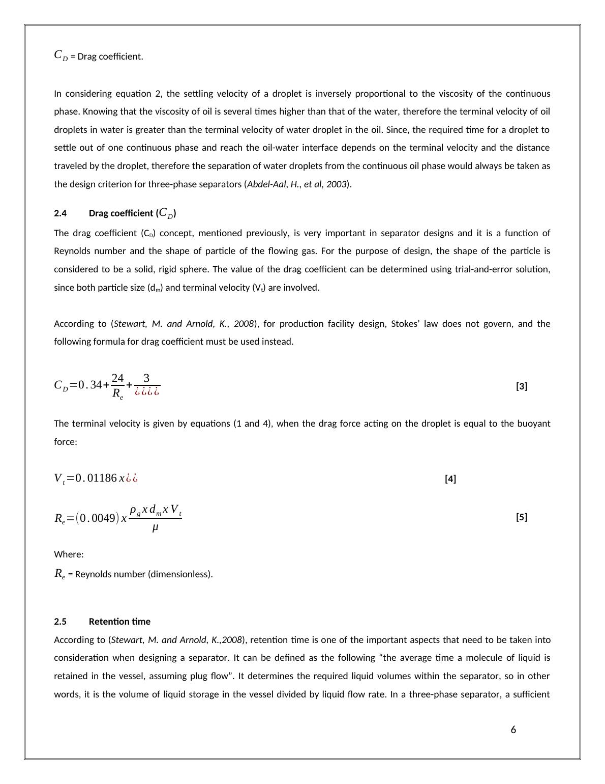
CD = Drag coefficient.In considering equation 2, the settling velocity of a droplet is inversely proportional to the viscosity of the continuousphase. Knowing that the viscosity of oil is several times higher than that of the water, therefore the terminal velocity of oildroplets in water is greater than the terminal velocity of water droplet in the oil. Since, the required time for a droplet tosettle out of one continuous phase and reach the oil-water interface depends on the terminal velocity and the distancetraveled by the droplet, therefore the separation of water droplets from the continuous oil phase would always be taken asthe design criterion for three-phase separators (Abdel-Aal, H., et al, 2003).2.4Drag coefficient (CD)The drag coefficient (CD) concept, mentioned previously, is very important in separator designs and it is a function ofReynolds number and the shape of particle of the flowing gas. For the purpose of design, the shape of the particle isconsidered to be a solid, rigid sphere. The value of the drag coefficient can be determined using trial-and-error solution,since both particle size (dm) and terminal velocity (Vt) are involved. According to (Stewart, M. and Arnold, K., 2008), for production facility design, Stokes’ law does not govern, and thefollowing formula for drag coefficient must be used instead.CD=0.34+24Re+3¿¿¿¿[3]The terminal velocity is given by equations (1 and 4), when the drag force acting on the droplet is equal to the buoyantforce:Vt=0.01186x¿¿[4]Re=(0.0049)xρgxdmxVtμ[5]Where:Re = Reynolds number (dimensionless).2.5Retention timeAccording to (Stewart, M. and Arnold, K.,2008), retention time is one of the important aspects that need to be taken intoconsideration when designing a separator. It can be defined as the following “the average time a molecule of liquid isretained in the vessel, assuming plug flow”. It determines the required liquid volumes within the separator, so in otherwords, it is the volume of liquid storage in the vessel divided by liquid flow rate. In a three-phase separator, a sufficient6
End of preview
Want to access all the pages? Upload your documents or become a member.
Related Documents
Purification Unitlg...
|62
|8801
|40