Investigating Truck Chassis Vibration: Natural Frequencies and Modes
VerifiedAdded on 2021/06/15
|16
|3527
|30
Report
AI Summary
This report investigates the vibrational characteristics of a truck chassis, focusing on natural frequencies and mode shapes, which are crucial for commercial vehicle performance. The study utilizes the finite element method to analyze the chassis's dynamic behavior under road excitation, engine operation, and transmission forces. The research explores the relationship between engine speed and natural frequencies, highlighting road excitation as a major disturbance. Furthermore, the report discusses chassis modifications aimed at increasing natural frequencies to an appropriate range, enhancing vehicle reliability and safety. The methodology includes finite element modeling using ANSYS, with detailed consideration of bolt and rivet joints, and the analysis of the first 30 modes of frequency. The results reveal the dominant modes of vibration, including torsional and bending modes, and their impact on the chassis's dynamic response. The findings provide valuable insights into the design and optimization of truck chassis to mitigate vibrations and improve overall vehicle performance.

Chassis 1
TRUCK CHASSIS VIBRATION
Student’s Name
Institution
City
Date
TRUCK CHASSIS VIBRATION
Student’s Name
Institution
City
Date
Paraphrase This Document
Need a fresh take? Get an instant paraphrase of this document with our AI Paraphraser
Chassis 2
Abstract
The article investigates characteristics of truck chassis vibrational such as the mode of shapes
and frequencies which are natural where the chassis of a truck form the backbone structure of
a vehicle in the commercial. If the truck runs along the road, the dynamic forces excite the
truck chassis due to the engine, the roughness of the road, transmission among other factors,
therefore, analysis of the modal by use of finite element method may be applied to determine
the mode of shapes and frequencies which are natural. The relation between the speed at
which the engine operates and the natural frequency have discussed and the results indicate
that the excitation of the road is the major truck chassis disturbance due to the frequencies
which are natural that lies inside the excitation of the road range of the frequency.
Advantages of the chassis with modification which causes the increase of the frequencies that
are natural and putting them in the range that is appropriate have also been explained.
Keywords: truck chassis, finite elements, modal analysis, vibration, dynamic
Chassis 3
Introduction
The response of simple dynamic structures which include plates, shells that are cylindrical
and beams which are uniform, could be obtained through equation solving of their motion,
however, several circumstances of practical either the properties of material vary geometrical
or the boundaries’ shape cannot be in known functions of mathematical terms be described.
This challenge is solved by seeking some solutions that are in numerical form and methods of
finite element. The industry of automotive is one the greatest users of modal analysis
technology, however, the behaviour of the modal of truck chassis is the most important part
of information for the dynamic behaviour of the truck for inspection. In this article the truck’s
chassis modal analysis has been researched on as a truck runs on the road there is the
excitement of the truck chassis caused by forces which are dynamically induced by the
roughness of the road, transmission and the engine.
Literature review
The vibrational features of a vehicle that are global is in relation to both its distribution of
mass and stiffness, the torsional modes and global bending of vibration frequencies are used
commonly as examples in structural performance of vehicles while, the stiffness of torsion
and bending influences the behaviour of the structure vibration in regards to the first natural
frequency. The truck’s chassis shape modes are very important at a certain point of natural
frequency in determining the point of mounting of components which include suspension,
engine and transmission among others hence, to include the effect of dynamic is very
important in the chassis designing.
(Henry, 2017)and (Khanna, 2017)made a research on 3530 FORD chassis for optimization
of thickness and main criteria to develop chassis got to be safety and reliability usually so as
for reliability to increase, the membranes of the chassis has to be increased which adds much
⊘ This is a preview!⊘
Do you want full access?
Subscribe today to unlock all pages.

Trusted by 1+ million students worldwide
Chassis 4
cost to the truck’s chassis. A study to find out the thickness that is optimum for the chassis
was conducted, analysis of linear static was also conducted for 3 kinds of chassis thickness
such as 4mm, 6mm and 5mm with a 16-ton load constant distributed. The study indicated the
thickness in the 4mm can in the place cross member chassis of 6mm be replaced without the
safety being affected.
(Kashem, et al., 2017)made a research on truck chassis of 4.5 tones comprising of C 2 side rail
sections and 5 numbers of cross member compared to excitations and roughness of the road.
The fixed components vibration to the chassis is as a result of the roughness of the road and
excitation were researched and an examination on the response of the chassis by the
distribution of stress and displacement. The locations that area suitable for engines and
system of the suspension was determined the findings of the shape of the mode and outcome
of the analysis showed that the main chassis disturbance is as a result of excitation of the
road.
(China, 2015)Studied chassis alternative materials such as Epoxy or Carbon, Epoxy or S-glass
and Epoxy or E-glass were applied as chassis materials in a variety of three cross-sections as
Box-section, I-section, and C-section. Chassis TATA 2515 EX was analysed. Finite element
analysis and 3D modelling analysis were conducted in ANSYS and Pro-E software in a
respective manner. The study showed that the Epoxy or Carbon section I-type has mechanical
properties that are much better such as weight stiffness and stiffness than other cross-sections
and materials.
(Dorst, 2015)Researched on the impact of cyclic loading in Gross Vehicle Weight of 36 tones
cargo truck. A chassis of 2.45m in width and 12.35m in length measurements was analysed
and load as a result of cargo was used as a load that is distributed uniformly that is divided
equally to the body of the cargo’s contact surfaces with chassis. The method of sub-
Paraphrase This Document
Need a fresh take? Get an instant paraphrase of this document with our AI Paraphraser
Chassis 5
modelling of Finite element method was applied to acquire results that are accurate at regions
with high stress. Information from accelerometer was as forces converted that has been used
as cyclic loading in components of sub-structure of the chassis. The results indicated that the
static load of the cargo leads more stresses than the cyclic load produced by the roughness of
the road.
Methodology
Many studies have been conducted on the chassis by a number of researchers (Gokhale,
2008)dynamically analysed a truck additionally in his method of truck simulation with
ANSYS Finite element package making sure that the vibrational structure modes are in a
suitable range, the vibrational ability was analysed.
(Khennane, 2013)Compared than the natural frequencies of chassis ladder with Finite element
and methods of experimental. (Heißing & Ersoy, 2010)Study into modal analysis and
dynamic of a space chassis that is, the complex chassis of dimension3 and transient response
analysed by use of superposition principle.
This article works on truck chassis of 6 tones which has mode shapes and natural frequencies,
it has been shortened by companies that are related for applying municipal service hereby,
facing the question it raises and also the challenge as to whether the natural frequencies of the
chassis with modification are in an appropriate range. In the researched model as compared to
the original model, bolts and rivets have been completely modelled and the shell element also
applied for analysis (Sheng, 2012). This element has a meshing that is more disciplined and
better as compared to various elements with the potential of attaining results that are accurate
with the meshing consisting of the dimensional 3 elements. It is valid to mention that the
results have proven by the results being compared from a model that is similar to the
proposed model by (Genta & Morello, 2008)
Chassis 6
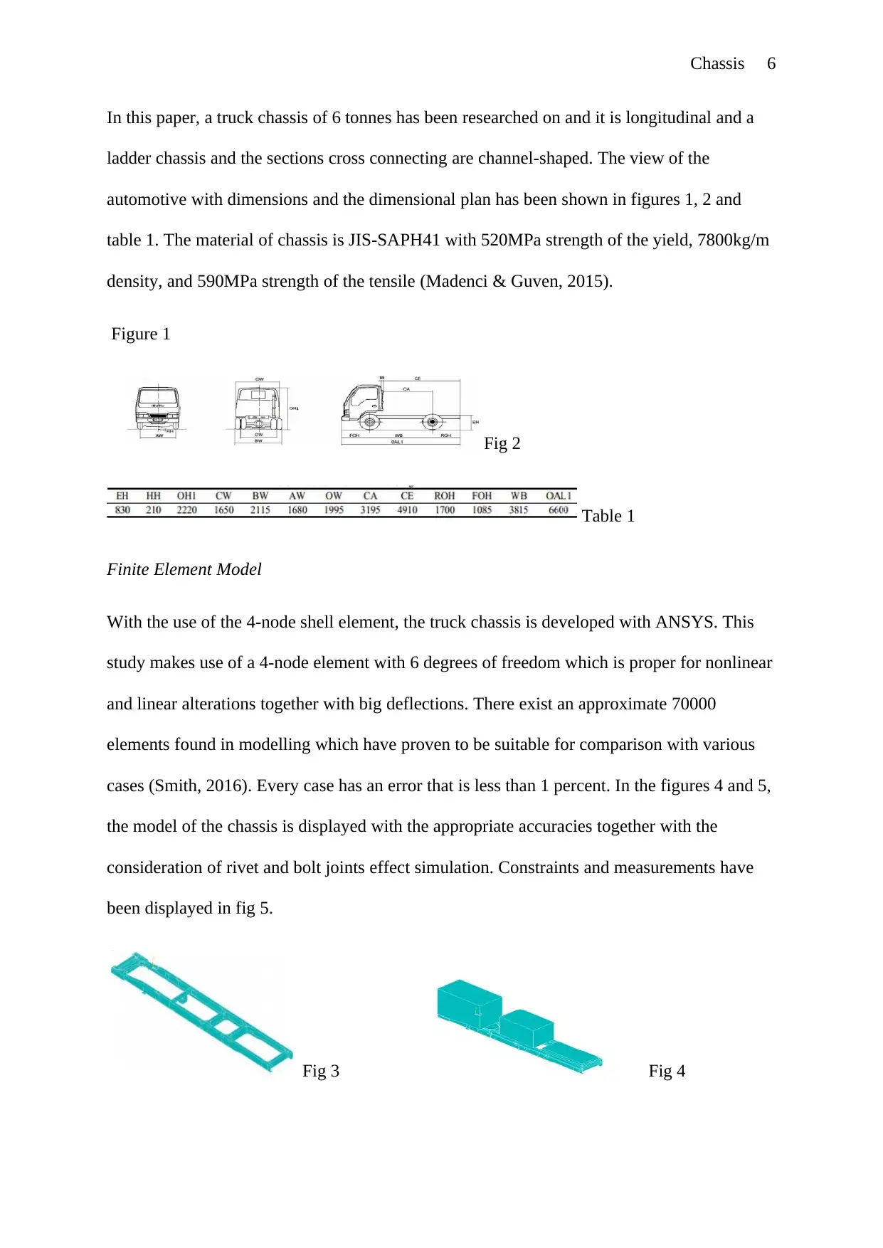
In this paper, a truck chassis of 6 tonnes has been researched on and it is longitudinal and a
ladder chassis and the sections cross connecting are channel-shaped. The view of the
automotive with dimensions and the dimensional plan has been shown in figures 1, 2 and
table 1. The material of chassis is JIS-SAPH41 with 520MPa strength of the yield, 7800kg/m
density, and 590MPa strength of the tensile (Madenci & Guven, 2015).
Figure 1
Fig 2
Table 1
Finite Element Model
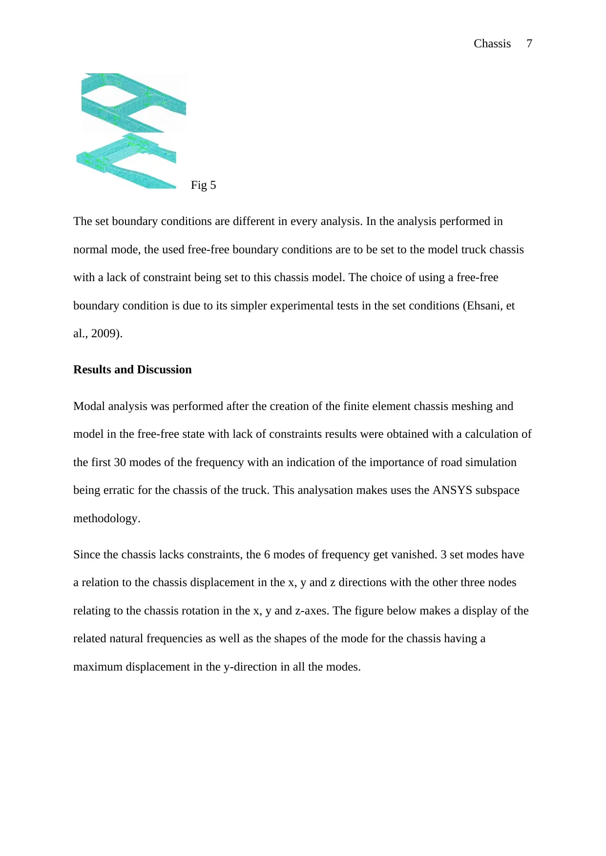
With the use of the 4-node shell element, the truck chassis is developed with ANSYS. This
study makes use of a 4-node element with 6 degrees of freedom which is proper for nonlinear
and linear alterations together with big deflections. There exist an approximate 70000
elements found in modelling which have proven to be suitable for comparison with various
cases (Smith, 2016). Every case has an error that is less than 1 percent. In the figures 4 and 5,
the model of the chassis is displayed with the appropriate accuracies together with the
consideration of rivet and bolt joints effect simulation. Constraints and measurements have
been displayed in fig 5.
Fig 3 Fig 4
⊘ This is a preview!⊘
Do you want full access?
Subscribe today to unlock all pages.

Trusted by 1+ million students worldwide
Chassis 7
Fig 5
The set boundary conditions are different in every analysis. In the analysis performed in
normal mode, the used free-free boundary conditions are to be set to the model truck chassis
with a lack of constraint being set to this chassis model. The choice of using a free-free
boundary condition is due to its simpler experimental tests in the set conditions (Ehsani, et
al., 2009).
Results and Discussion
Modal analysis was performed after the creation of the finite element chassis meshing and
model in the free-free state with lack of constraints results were obtained with a calculation of
the first 30 modes of the frequency with an indication of the importance of road simulation
being erratic for the chassis of the truck. This analysation makes uses the ANSYS subspace
methodology.
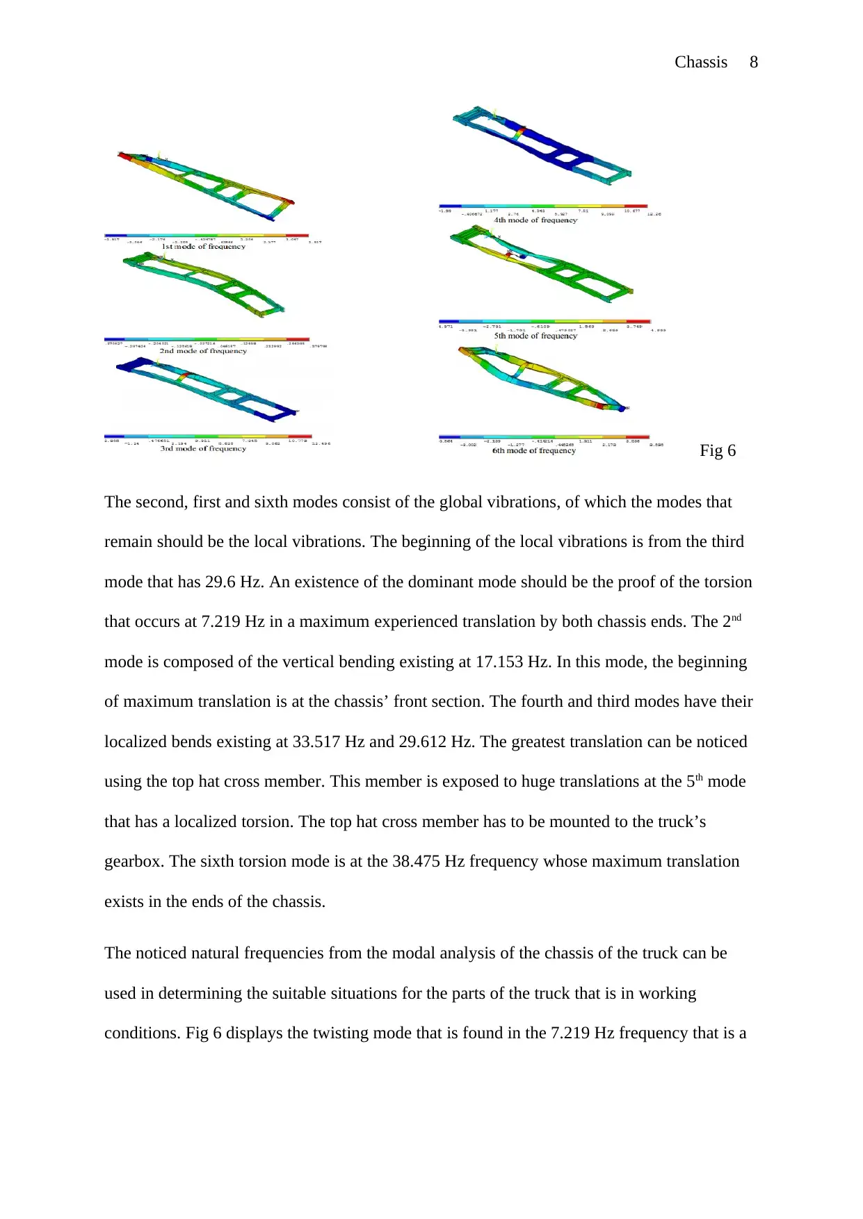
Since the chassis lacks constraints, the 6 modes of frequency get vanished. 3 set modes have
a relation to the chassis displacement in the x, y and z directions with the other three nodes
relating to the chassis rotation in the x, y and z-axes. The figure below makes a display of the
related natural frequencies as well as the shapes of the mode for the chassis having a
maximum displacement in the y-direction in all the modes.
Paraphrase This Document
Need a fresh take? Get an instant paraphrase of this document with our AI Paraphraser
Chassis 8
Fig 6
The second, first and sixth modes consist of the global vibrations, of which the modes that
remain should be the local vibrations. The beginning of the local vibrations is from the third
mode that has 29.6 Hz. An existence of the dominant mode should be the proof of the torsion
that occurs at 7.219 Hz in a maximum experienced translation by both chassis ends. The 2nd
mode is composed of the vertical bending existing at 17.153 Hz. In this mode, the beginning
of maximum translation is at the chassis’ front section. The fourth and third modes have their
localized bends existing at 33.517 Hz and 29.612 Hz. The greatest translation can be noticed
using the top hat cross member. This member is exposed to huge translations at the 5th mode
that has a localized torsion. The top hat cross member has to be mounted to the truck’s
gearbox. The sixth torsion mode is at the 38.475 Hz frequency whose maximum translation
exists in the ends of the chassis.
The noticed natural frequencies from the modal analysis of the chassis of the truck can be
used in determining the suitable situations for the parts of the truck that is in working
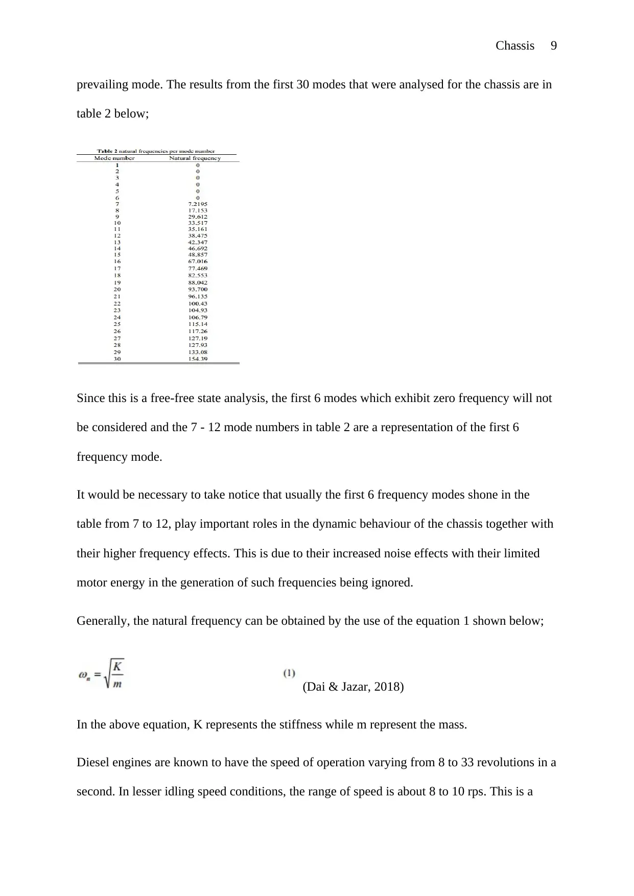
conditions. Fig 6 displays the twisting mode that is found in the 7.219 Hz frequency that is a
Chassis 9
prevailing mode. The results from the first 30 modes that were analysed for the chassis are in
table 2 below;
Since this is a free-free state analysis, the first 6 modes which exhibit zero frequency will not
be considered and the 7 - 12 mode numbers in table 2 are a representation of the first 6
frequency mode.
It would be necessary to take notice that usually the first 6 frequency modes shone in the
table from 7 to 12, play important roles in the dynamic behaviour of the chassis together with
their higher frequency effects. This is due to their increased noise effects with their limited
motor energy in the generation of such frequencies being ignored.
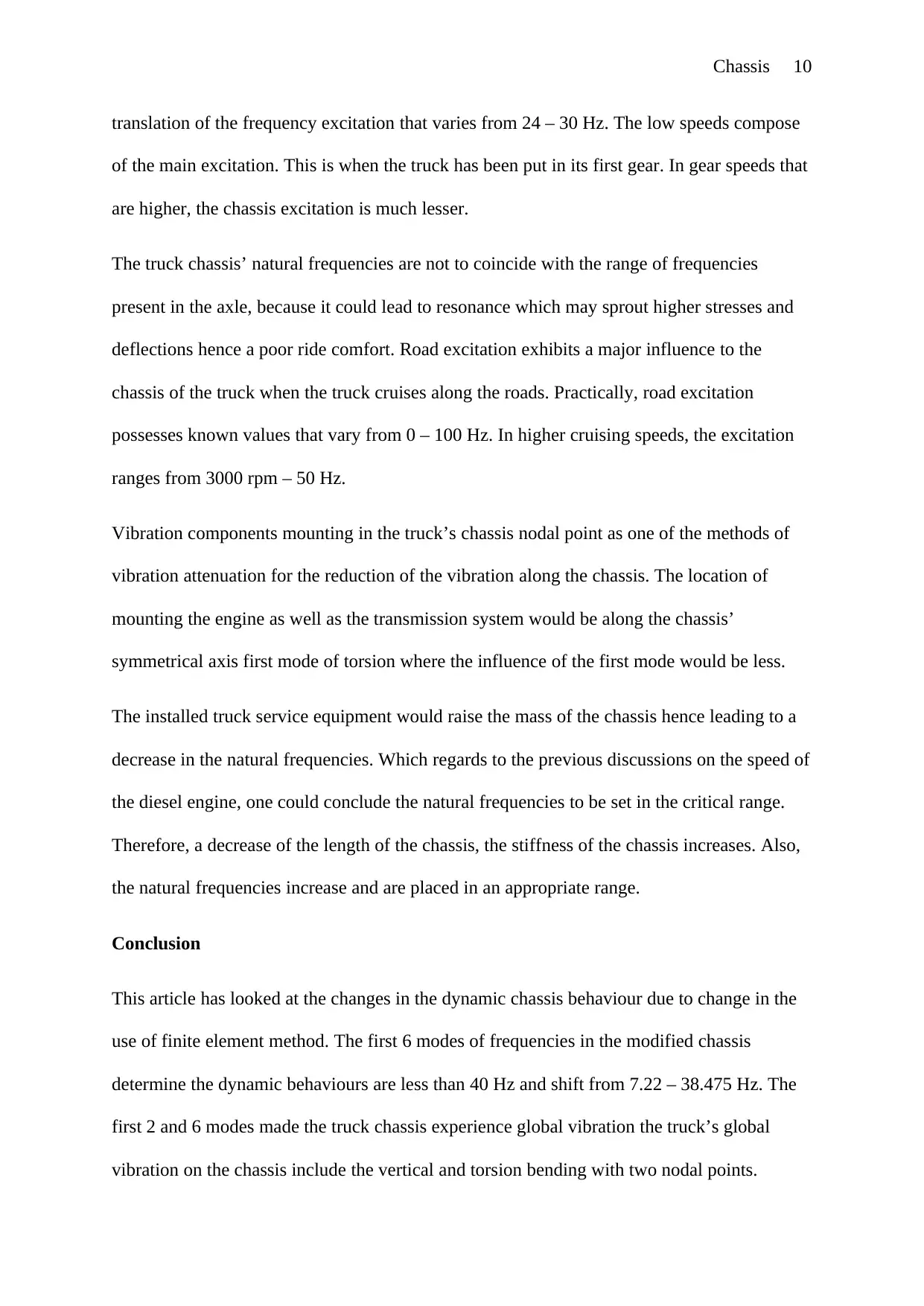
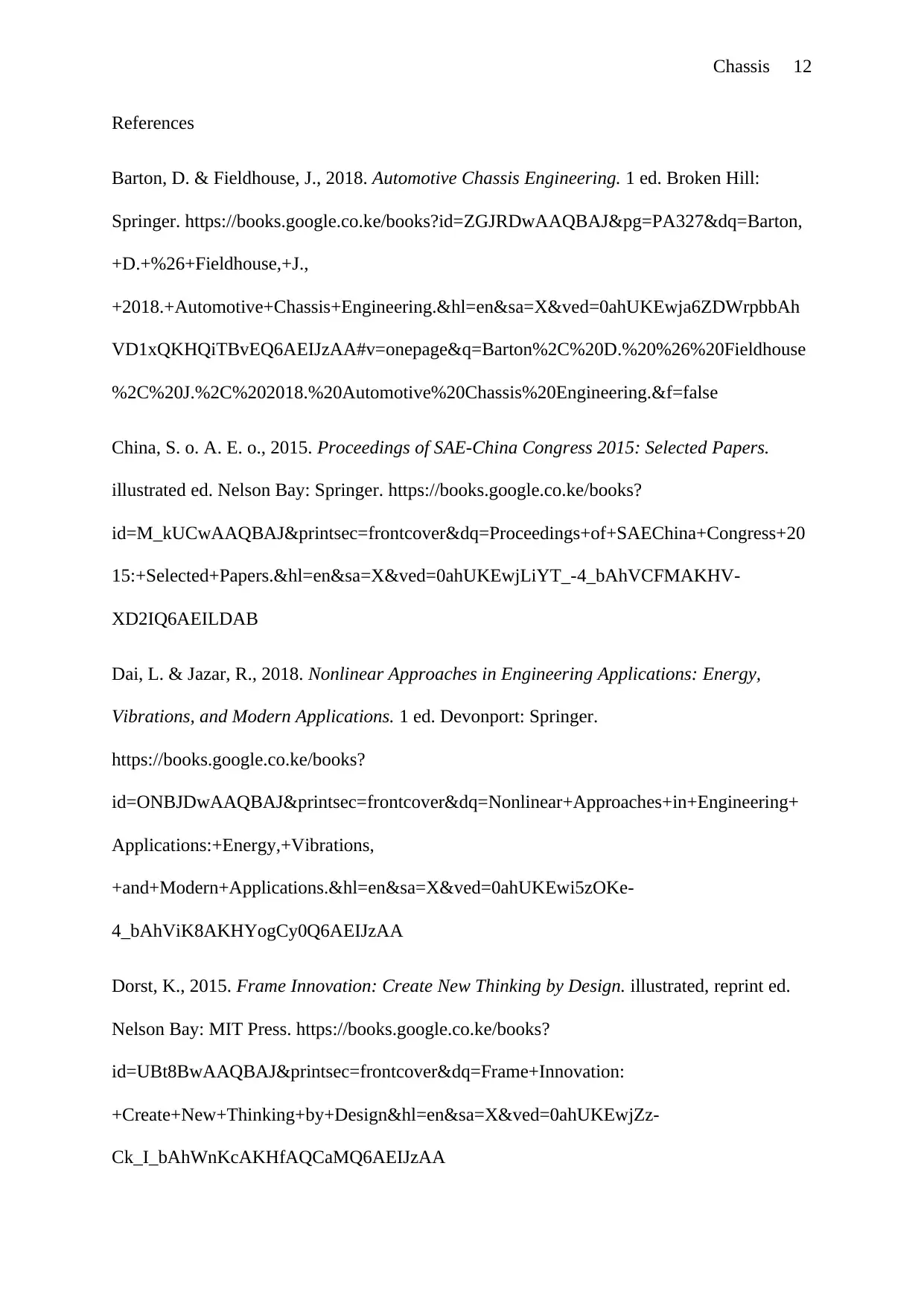
Generally, the natural frequency can be obtained by the use of the equation 1 shown below;
(Dai & Jazar, 2018)
In the above equation, K represents the stiffness while m represent the mass.
Diesel engines are known to have the speed of operation varying from 8 to 33 revolutions in a
second. In lesser idling speed conditions, the range of speed is about 8 to 10 rps. This is a
⊘ This is a preview!⊘
Do you want full access?
Subscribe today to unlock all pages.

Trusted by 1+ million students worldwide
Chassis 10
translation of the frequency excitation that varies from 24 – 30 Hz. The low speeds compose
of the main excitation. This is when the truck has been put in its first gear. In gear speeds that
are higher, the chassis excitation is much lesser.
The truck chassis’ natural frequencies are not to coincide with the range of frequencies
present in the axle, because it could lead to resonance which may sprout higher stresses and
deflections hence a poor ride comfort. Road excitation exhibits a major influence to the
chassis of the truck when the truck cruises along the roads. Practically, road excitation
possesses known values that vary from 0 – 100 Hz. In higher cruising speeds, the excitation
ranges from 3000 rpm – 50 Hz.
Vibration components mounting in the truck’s chassis nodal point as one of the methods of
vibration attenuation for the reduction of the vibration along the chassis. The location of
mounting the engine as well as the transmission system would be along the chassis’
symmetrical axis first mode of torsion where the influence of the first mode would be less.
The installed truck service equipment would raise the mass of the chassis hence leading to a
decrease in the natural frequencies. Which regards to the previous discussions on the speed of
the diesel engine, one could conclude the natural frequencies to be set in the critical range.
Therefore, a decrease of the length of the chassis, the stiffness of the chassis increases. Also,
the natural frequencies increase and are placed in an appropriate range.
Conclusion
This article has looked at the changes in the dynamic chassis behaviour due to change in the
use of finite element method. The first 6 modes of frequencies in the modified chassis
determine the dynamic behaviours are less than 40 Hz and shift from 7.22 – 38.475 Hz. The
first 2 and 6 modes made the truck chassis experience global vibration the truck’s global
vibration on the chassis include the vertical and torsion bending with two nodal points.
Paraphrase This Document
Need a fresh take? Get an instant paraphrase of this document with our AI Paraphraser

Chassis 11
Since there is an increase in the mass of the chassis due to equipment installed, the natural
frequencies would be far from the natural range that has a compensation with the increased
stiffness of the chassis. The use of this method is able to prevent resonance phenomenon as
well as unusual vibration of the chassis and place the natural frequencies in the natural range.
Chassis 12
References
Barton, D. & Fieldhouse, J., 2018. Automotive Chassis Engineering. 1 ed. Broken Hill:
Springer. https://books.google.co.ke/books?id=ZGJRDwAAQBAJ&pg=PA327&dq=Barton,
+D.+%26+Fieldhouse,+J.,
+2018.+Automotive+Chassis+Engineering.&hl=en&sa=X&ved=0ahUKEwja6ZDWrpbbAh
VD1xQKHQiTBvEQ6AEIJzAA#v=onepage&q=Barton%2C%20D.%20%26%20Fieldhouse
%2C%20J.%2C%202018.%20Automotive%20Chassis%20Engineering.&f=false
China, S. o. A. E. o., 2015. Proceedings of SAE-China Congress 2015: Selected Papers.
illustrated ed. Nelson Bay: Springer. https://books.google.co.ke/books?
id=M_kUCwAAQBAJ&printsec=frontcover&dq=Proceedings+of+SAEChina+Congress+20
15:+Selected+Papers.&hl=en&sa=X&ved=0ahUKEwjLiYT_-4_bAhVCFMAKHV-
XD2IQ6AEILDAB
Dai, L. & Jazar, R., 2018. Nonlinear Approaches in Engineering Applications: Energy,
Vibrations, and Modern Applications. 1 ed. Devonport: Springer.
https://books.google.co.ke/books?
id=ONBJDwAAQBAJ&printsec=frontcover&dq=Nonlinear+Approaches+in+Engineering+
Applications:+Energy,+Vibrations,
+and+Modern+Applications.&hl=en&sa=X&ved=0ahUKEwi5zOKe-
4_bAhViK8AKHYogCy0Q6AEIJzAA
Dorst, K., 2015. Frame Innovation: Create New Thinking by Design. illustrated, reprint ed.
Nelson Bay: MIT Press. https://books.google.co.ke/books?
id=UBt8BwAAQBAJ&printsec=frontcover&dq=Frame+Innovation:
+Create+New+Thinking+by+Design&hl=en&sa=X&ved=0ahUKEwjZz-
Ck_I_bAhWnKcAKHfAQCaMQ6AEIJzAA
⊘ This is a preview!⊘
Do you want full access?
Subscribe today to unlock all pages.

Trusted by 1+ million students worldwide
1 out of 16
Related Documents
Your All-in-One AI-Powered Toolkit for Academic Success.
+13062052269
info@desklib.com
Available 24*7 on WhatsApp / Email
![[object Object]](/_next/static/media/star-bottom.7253800d.svg)
Unlock your academic potential
Copyright © 2020–2026 A2Z Services. All Rights Reserved. Developed and managed by ZUCOL.


