CHE 3040 Unit Operations Laboratory I: Centrifugal Pump Analysis
VerifiedAdded on 2019/10/18
|5
|1620
|452
Practical Assignment
AI Summary
This assignment details a laboratory experiment focused on characterizing a centrifugal pump's performance. The experiment investigates the effects of varying flow rates and speeds on critical parameters, including pump head, efficiency, and brake horsepower (BHP). The procedure involves measuring suction and discharge pressures, torque, and rotational speed at different flow rates. The analysis section requires plotting pump head, efficiency, and BHP versus flow rate curves for different pump speeds, and calculating the net positive suction head available (NPSHa). The assignment requires the student to explain observed trends, compare results with typical centrifugal pump curves, determine the optimal operating flow rate, and analyze reverse flow behavior. The goal is to understand how these factors influence pump performance and to relate the experimental results to established engineering principles. The report includes detailed calculations, plots, and explanations of the observed phenomena, providing a comprehensive understanding of centrifugal pump operation.
CHE 3040 UNIT OPERATIONS LABORATORY I
Centrifugal Pump Characteristics
Purpose
The purpose of this experiment is to determine the effect of flow rate and speed on the
head, efficiency, and brake horsepower requirement of a centrifugal pump.
Background/Theory
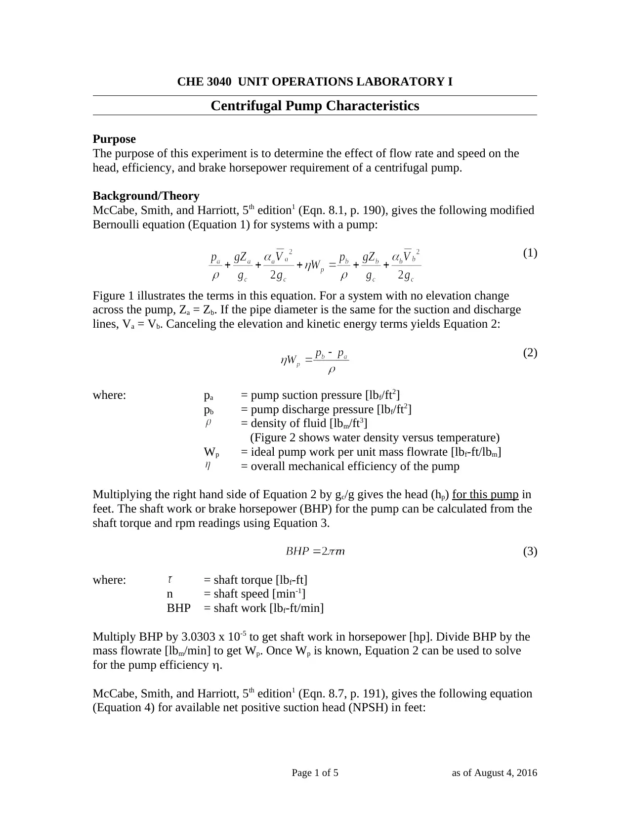
McCabe, Smith, and Harriott, 5th edition1 (Eqn. 8.1, p. 190), gives the following modified
Bernoulli equation (Equation 1) for systems with a pump:
(1)
Figure 1 illustrates the terms in this equation. For a system with no elevation change
across the pump, Za = Zb. If the pipe diameter is the same for the suction and discharge
lines, Va = Vb. Canceling the elevation and kinetic energy terms yields Equation 2:
(2)
where: pa = pump suction pressure [lbf/ft2]
pb = pump discharge pressure [lbf/ft2]
= density of fluid [lbm/ft3]
(Figure 2 shows water density versus temperature)
Wp = ideal pump work per unit mass flowrate [lbf-ft/lbm]
= overall mechanical efficiency of the pump
Multiplying the right hand side of Equation 2 by gc/g gives the head (hp) for this pump in
feet. The shaft work or brake horsepower (BHP) for the pump can be calculated from the
shaft torque and rpm readings using Equation 3.
(3)
where: = shaft torque [lbf-ft]
n = shaft speed [min-1]
BHP = shaft work [lbf-ft/min]
Multiply BHP by 3.0303 x 10⁻⁵ to get shaft work in horsepower [hp]. Divide BHP by the
mass flowrate [lbm/min] to get Wp. Once Wp is known, Equation 2 can be used to solve
for the pump efficiency .
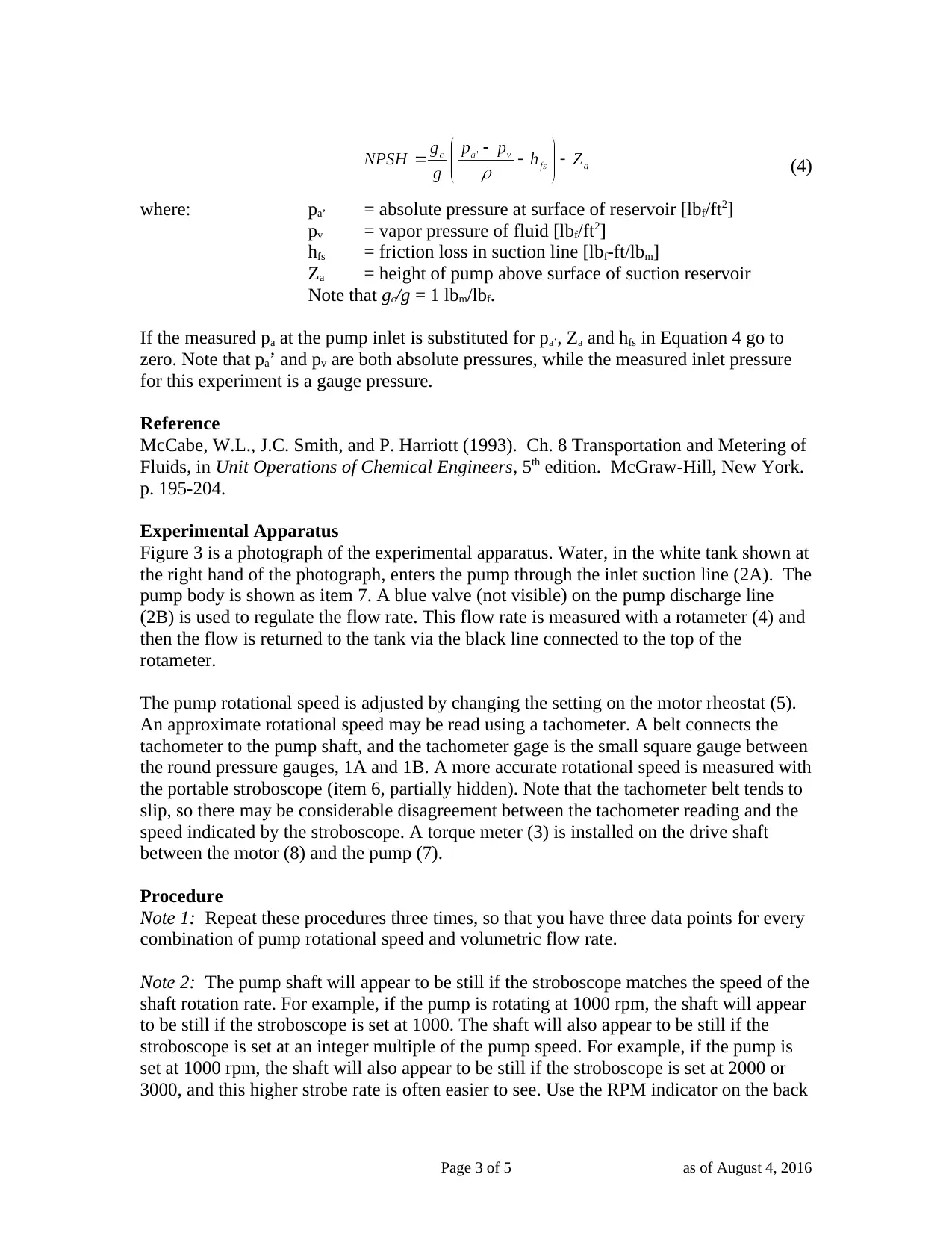
McCabe, Smith, and Harriott, 5th edition1 (Eqn. 8.7, p. 191), gives the following equation
(Equation 4) for available net positive suction head (NPSH) in feet:
Page 1 of 5 as of August 4, 2016
Paraphrase This Document
Need a fresh take? Get an instant paraphrase of this document with our AI Paraphraser
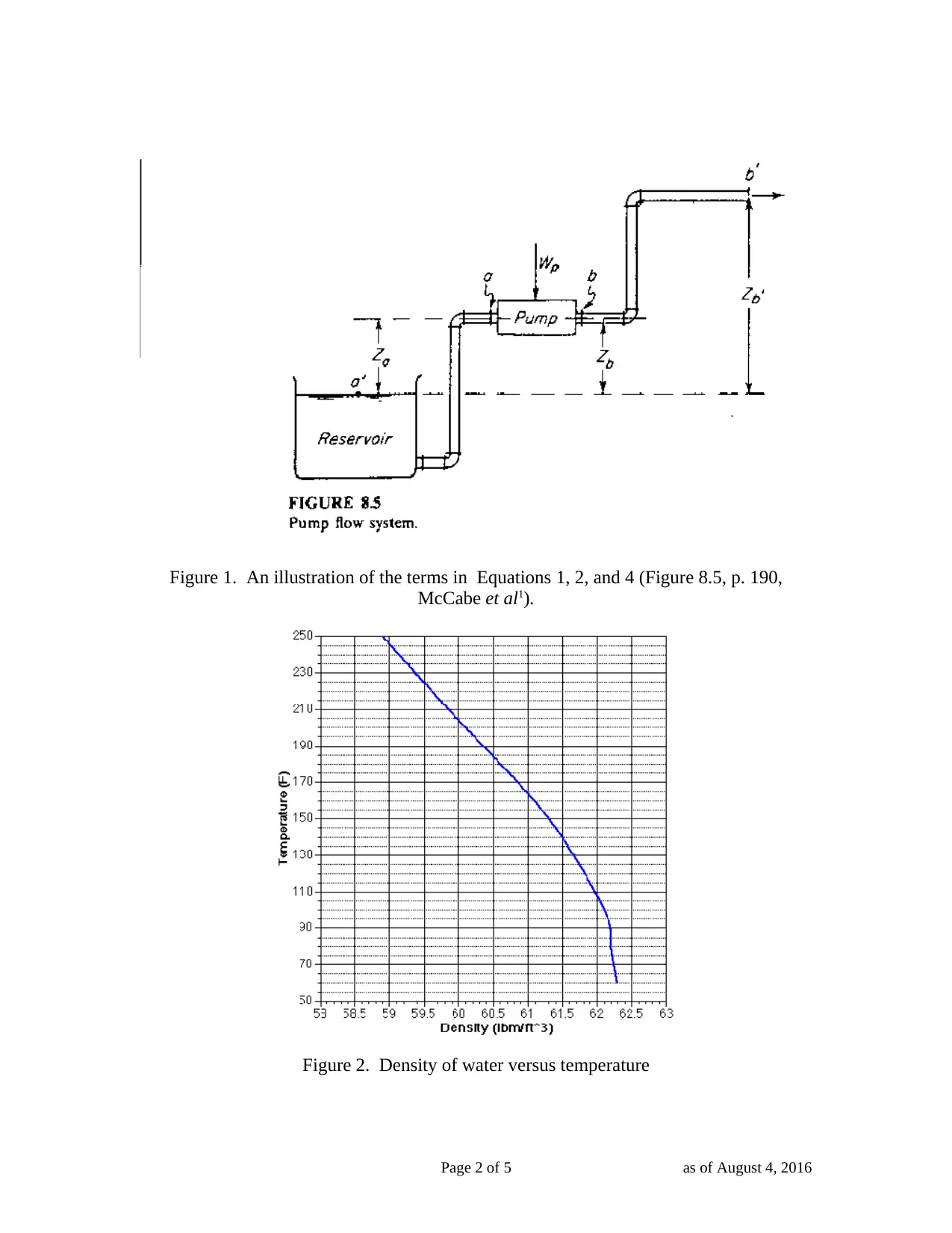
Figure 1. An illustration of the terms in Equations 1, 2, and 4 (Figure 8.5, p. 190,
McCabe et al1).
Figure 2. Density of water versus temperature
Page 2 of 5 as of August 4, 2016
McCabe et al1).
Figure 2. Density of water versus temperature
Page 2 of 5 as of August 4, 2016
(4)
where: pa’ = absolute pressure at surface of reservoir [lbf/ft2]
pv = vapor pressure of fluid [lbf/ft2]
hfs = friction loss in suction line [lbf-ft/lbm]
Za = height of pump above surface of suction reservoir
Note that gc/g = 1 lbm/lbf.
If the measured pa at the pump inlet is substituted for pa’, Za and hfs in Equation 4 go to
zero. Note that pa’ and pv are both absolute pressures, while the measured inlet pressure
for this experiment is a gauge pressure.
Reference
McCabe, W.L., J.C. Smith, and P. Harriott (1993). Ch. 8 Transportation and Metering of
Fluids, in Unit Operations of Chemical Engineers, 5th edition. McGraw-Hill, New York.
p. 195-204.
Experimental Apparatus
Figure 3 is a photograph of the experimental apparatus. Water, in the white tank shown at
the right hand of the photograph, enters the pump through the inlet suction line (2A). The
pump body is shown as item 7. A blue valve (not visible) on the pump discharge line
(2B) is used to regulate the flow rate. This flow rate is measured with a rotameter (4) and
then the flow is returned to the tank via the black line connected to the top of the
rotameter.
The pump rotational speed is adjusted by changing the setting on the motor rheostat (5).
An approximate rotational speed may be read using a tachometer. A belt connects the
tachometer to the pump shaft, and the tachometer gage is the small square gauge between
the round pressure gauges, 1A and 1B. A more accurate rotational speed is measured with
the portable stroboscope (item 6, partially hidden). Note that the tachometer belt tends to
slip, so there may be considerable disagreement between the tachometer reading and the
speed indicated by the stroboscope. A torque meter (3) is installed on the drive shaft
between the motor (8) and the pump (7).
Procedure
Note 1: Repeat these procedures three times, so that you have three data points for every
combination of pump rotational speed and volumetric flow rate.
Note 2: The pump shaft will appear to be still if the stroboscope matches the speed of the
shaft rotation rate. For example, if the pump is rotating at 1000 rpm, the shaft will appear
to be still if the stroboscope is set at 1000. The shaft will also appear to be still if the
stroboscope is set at an integer multiple of the pump speed. For example, if the pump is
set at 1000 rpm, the shaft will also appear to be still if the stroboscope is set at 2000 or
3000, and this higher strobe rate is often easier to see. Use the RPM indicator on the back
Page 3 of 5 as of August 4, 2016
⊘ This is a preview!⊘
Do you want full access?
Subscribe today to unlock all pages.

Trusted by 1+ million students worldwide
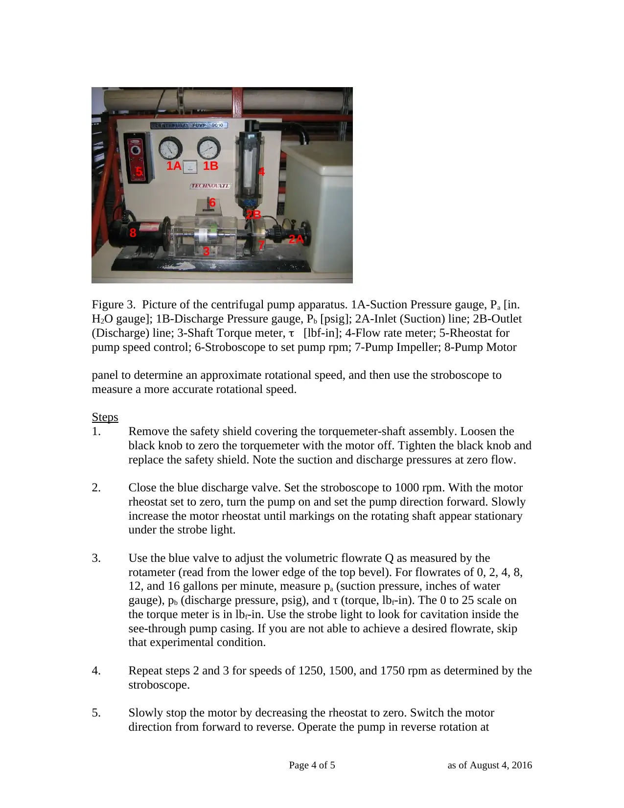
Figure 3. Picture of the centrifugal pump apparatus. 1A-Suction Pressure gauge, Pa [in.
H2O gauge]; 1B-Discharge Pressure gauge, Pb [psig]; 2A-Inlet (Suction) line; 2B-Outlet
(Discharge) line; 3-Shaft Torque meter, [lbf-in]; 4-Flow rate meter; 5-Rheostat for
pump speed control; 6-Stroboscope to set pump rpm; 7-Pump Impeller; 8-Pump Motor
panel to determine an approximate rotational speed, and then use the stroboscope to
measure a more accurate rotational speed.
Steps
1. Remove the safety shield covering the torquemeter-shaft assembly. Loosen the
black knob to zero the torquemeter with the motor off. Tighten the black knob and
replace the safety shield. Note the suction and discharge pressures at zero flow.
2. Close the blue discharge valve. Set the stroboscope to 1000 rpm. With the motor
rheostat set to zero, turn the pump on and set the pump direction forward. Slowly
increase the motor rheostat until markings on the rotating shaft appear stationary
under the strobe light.
3. Use the blue valve to adjust the volumetric flowrate Q as measured by the
rotameter (read from the lower edge of the top bevel). For flowrates of 0, 2, 4, 8,
12, and 16 gallons per minute, measure pa (suction pressure, inches of water
gauge), pb (discharge pressure, psig), and τ (torque, lbf-in). The 0 to 25 scale on
the torque meter is in lbf-in. Use the strobe light to look for cavitation inside the
see-through pump casing. If you are not able to achieve a desired flowrate, skip
that experimental condition.
4. Repeat steps 2 and 3 for speeds of 1250, 1500, and 1750 rpm as determined by the
stroboscope.
5. Slowly stop the motor by decreasing the rheostat to zero. Switch the motor
direction from forward to reverse. Operate the pump in reverse rotation at
Page 4 of 5 as of August 4, 2016
1A 1B
3
4
2A
2B
5
6
7
8
Paraphrase This Document
Need a fresh take? Get an instant paraphrase of this document with our AI Paraphraser
different speeds and observe the flowrate with the discharge valve wide open.
What you should see is some flow at maximum rpm, but not enough to lift the
float in the rotameter.
Analysis
Note: For each condition (rpm and flowrate), show the mean, not the raw data. Also
show the 95 % confidence interval for each condition if you complete the lab after that
has been discussed in lecture.
1. Plot pump head (hp, feet of water) versus volumetric flowrate (Q, gpm) curves
(smooth line between data points) for each of the four pump speeds. Put all four
curves on the same plot, and label each curve with the correct rpm value.
2. Plot the pump efficiency in percent versus Q in gpm, again with curves for
constant rpm.
3. Plot the brake horsepower (BHP in hp) versus Q in gpm, again with curves for
constant rpm.
4. For your 1750 rpm data, plot the net positive suction head available (NPSHa, in
feet) versus the volumetric flowrate.
5. Explain the trends observed in your pump curves, and compare them with typical
centrifugal pump curves in the literature. Is the pump efficiency reasonable? If
not, offer possible explanations.
6. For a given impeller speed, what is the most desirable operating flowrate for this
pump? Justify your answer. Explain the decline in performance when the pump is
operated at flowrates other than the optimum.
7. Compare the reverse flows qualitatively to what happened with forward rotation,
and explain the differences.
Page 5 of 5 as of August 4, 2016
1 out of 5
Your All-in-One AI-Powered Toolkit for Academic Success.
+13062052269
info@desklib.com
Available 24*7 on WhatsApp / Email
![[object Object]](/_next/static/media/star-bottom.7253800d.svg)
Unlock your academic potential
Copyright © 2020–2025 A2Z Services. All Rights Reserved. Developed and managed by ZUCOL.