System Science and Engineering: Chenab Bridge Design Analysis
VerifiedAdded on 2023/06/04
|13
|2590
|277
Report
AI Summary
This report provides a comprehensive analysis of the Chenab Bridge, a significant engineering project undertaken by the Indian Railway Corporation in the Jammu and Kashmir region. It details the preliminary and detailed structural design, considering factors like seismic activity and high wind forces. The report covers functional criteria, design engineering activities, and the evolution of design details, including the integration of subsystems. Design requirements, such as adherence to Indian, British, and Eurocode standards, are thoroughly examined. The report also discusses the evaluation and validation processes, including deterministic and probabilistic danger analyses, and the design tools used, such as Tekla Structures. The Chenab Bridge is a steel arch railway bridge. The report also describes the evaluation and validation of the bridge.
The Chenab Bridge 1
System science and engineering
The Chenab Bridge
NAME: SHAIK ZAKIR HUSSAIN
ID : 12046748
CENTRAL QUEENSLAND UNIVERSITY
MELB - Campus
System science and engineering
The Chenab Bridge
NAME: SHAIK ZAKIR HUSSAIN
ID : 12046748
CENTRAL QUEENSLAND UNIVERSITY
MELB - Campus
Paraphrase This Document
Need a fresh take? Get an instant paraphrase of this document with our AI Paraphraser
The Chenab Bridge 2
Table of Contents
Executive summary.........................................................................................................................2
Introduction......................................................................................................................................3
Preliminary Design..........................................................................................................................4
Functional criteria........................................................................................................................5
Design engineering activities.......................................................................................................6
Detailed design................................................................................................................................6
Design requirements....................................................................................................................6
Evolution of design detail............................................................................................................8
Integration of subsystems.............................................................................................................9
Design tools................................................................................................................................10
Evaluation and validation of Chenab Bridge.................................................................................11
Evaluation..................................................................................................................................11
Validation...................................................................................................................................12
Conclusion.....................................................................................................................................12
Reference.......................................................................................................................................13
The Chenab Bridge 3
Executive summary
Bridges are the structures that provide backings to perpendicular loads of lateral movement
sandwiched between two positions. Bridges are built to uphold the movement over the physical
hindrance along the travel way such as, water body, highway, or gorge. Such kind of structure is
extra multifaceted as it consist of so many complex designs along with a number of participants.
Indian Railway Corporation has embarked on a huge project of building a new-fangled rail line
route between Municipal of Jammu and Kasmir. The development consisted of massive tunnels
and bridges constructed in highly rocky and hilly topography. The orientation runs accross a
deep valley of River Chenab that require building of a lengthy distance rail line passage. The key
element of Bridge Chenab is its 467 m stretched hardened arch central length sited
approximately 320 metres over the river surface. The research describes primarily the
preliminary and detailed structural design, but partially also the evaluation and validation of the
bridge. In the design exertion both domestic Indian Standard codes along with a number of
global codes had to be charted bearing in mind that the design principles match the building
principles.
⊘ This is a preview!⊘
Do you want full access?
Subscribe today to unlock all pages.

Trusted by 1+ million students worldwide
The Chenab Bridge 4
Introduction
Indian Railway Corporation embarked on a huge development of building of a novel rail
line route between in the Municipal of Jammu and Kashmir, between Udhampur and Baramulla.
The venture had been professed as a countrywide development scheme. The arrangement
comprised of several tunnels and bridges that were to be executed in extremely rocky and hilly
topography, with the problematic Himalayan geology Pulkkinen, etal. (2012). The infrastructure
crosses a profound valley of the River Chenab that required building of a long-span bridge. The
Bridge is situated in the Jammu and Kashmir region in the northern front of India. It runs across
the Chenab Water body neighboring the rural community of Kauri. It is a subproject of the new
Baramulla−Srinagar−Udhamptur rail line construction. The total length of the bridge is 1315
metres. The free span length of the bridge is 467 metres, measured from the seeming beneath of
the river, the stature of the bridge deck is 350 metres. As a consequence, Bridge Chenab is the
largest and longest-spanning rail line bridge of its kind in worldwide. It holds nearly 25,000 tons
of steel.
The Chenab Bridge was planned to be finalized by the end of December 2009. However,
In September 2008 it was publicized that the development Scheme was stopped temporarily even
with the accomplishment of groundwork of the approach viaduct India, (2008). Starting mid-
2009, it was agreed that the initial course to resume and the bridge would be constructed as
initially scheduled. On the other hand, it was decided that the key length of the bridge would be
revised to be 467 m. Chenab Bridge is an arch bridge entirely made of steel. Also the sundeck of
the bridge is out of steel. Bases and the approach overpass piers are out of concrete. The arch
was built by means of a cableway crane. In actual fact, all the assemblage links are bolted. The
Paraphrase This Document
Need a fresh take? Get an instant paraphrase of this document with our AI Paraphraser
The Chenab Bridge 5
quantity of bolts is about 600,000. The structure is established on the bedrock. The bases of the
arch are roughly 40 m tall and 50 m wide.
Preliminary Design
The Chenab Bridge is situated in seismically active region. Owing to the tunneling effects
in the valleys, the site also experiences high wind forces. To endure this, a preliminary design
and as series of tests were conducted in Force Technology Laboratory in Denmark. The
preliminary design was executed to find out the most feasible (economical, long lasting, and
most efficient) type of bridge and method of construction. Mitchell, (2008).
Functional criteria
Preliminary design of the key bridge necessitude contemplation of several extra
considerations, such as composite action, fatigue, secondary demand effects, global stability etc.
It as well required that such a special bridge is calculated to realize a reliable degree of
dependability for all force cases, and that design principles equal the building principles.
A series of studies were carried out to determine the most appropriate properties and
sections. First, Wind characteristics were considered in-depth in the first portion of the wind-
tunnel analysis platform with big size scale model of the landscape. The study was envisioned to
define the exact design wind speed. Secondly, section-model test were carried out to achieve
smooth input for wind forces and investigative wind-caused vibration reaction working out.
Thirdly, Deck unit was analyzed also with aero elastic analysis to find factors for vortex-caused
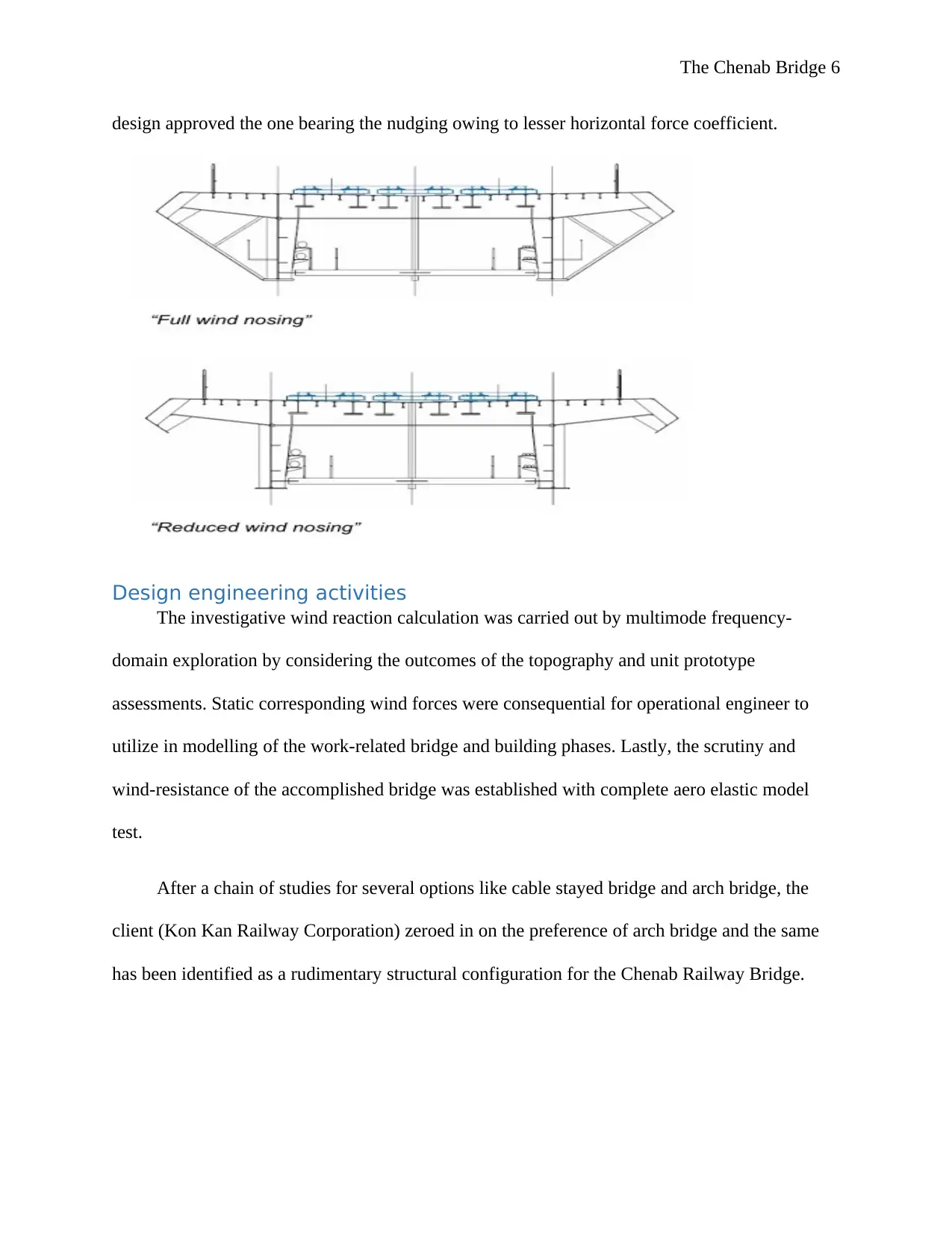
vibration inquiry. Two deck forms were investigated: with and without wind nudging. The
The Chenab Bridge 6
design approved the one bearing the nudging owing to lesser horizontal force coefficient.
Design engineering activities
The investigative wind reaction calculation was carried out by multimode frequency-
domain exploration by considering the outcomes of the topography and unit prototype
assessments. Static corresponding wind forces were consequential for operational engineer to
utilize in modelling of the work-related bridge and building phases. Lastly, the scrutiny and
wind-resistance of the accomplished bridge was established with complete aero elastic model
test.
After a chain of studies for several options like cable stayed bridge and arch bridge, the
client (Kon Kan Railway Corporation) zeroed in on the preference of arch bridge and the same
has been identified as a rudimentary structural configuration for the Chenab Railway Bridge.
⊘ This is a preview!⊘
Do you want full access?
Subscribe today to unlock all pages.

Trusted by 1+ million students worldwide
The Chenab Bridge 7
Detailed design
Generally a bridge is examined as a plane structure. For that reason, only 3 elementary
equalities of symmetry, ought to be gratified conferring to the functional mechanism. These
equalities are as:
∑FX=0, ∑FY=0, ∑M=0,
Any building satiating these 3 equalities is a practicable building. If a building flops to fulfill
these 3 equalities is not realistic. On the other hand, a bridge is not a 2-dimensional assembly
despite the fact that it is evaluated as a 2-dimensional assembly often. This deliberation of 2-
dimensional examines for bridges is utilized for easiness and is recognized internationally.
Design requirements
The bridge Proprietor set stern instructions and principles that were to be complied within
the design. Indian Rail line Principles (IRS Standards) had to be utilized where valid. British
Standards, Eurocodes and other international standards as well as UIC Standards could be
utilized as a complement.
Below are selected design standards taken used in the design of the bridge:
Limit state values of modelling had been agreed to be charted in accordance with British
Standard (BS) codes
Calculation of wind load special effects in accordance with wind tunnel assessments
Site detailed seismic ranges technologically advanced by Indian Institute of Technology
(IIT) Roorkee
Establishment of Euro code 8 for ductility describing of towering and muffled rectangular
RCC piers
Paraphrase This Document
Need a fresh take? Get an instant paraphrase of this document with our AI Paraphraser
The Chenab Bridge 8
Establishment of long welded rail (LWR) over the structures and consequential force
determination in accordance with UIC – 774-3R guiding principles
Blast resilient modelling has been utilized
Design inspection for fatigue in accordance with British Standards (BS) codes
Distortion restrictions in accordance with principles of UIC – 776-2R and UIC 776 -3R
course of action
Redundancy made available in the buildings, for lesser level of task in the course of
misfortunes and contrary to breakdown in extreme cases of one pier failure.
The design speed of the rail line was agreed to be 100 kilometres per hour and the design
lifespan set to be 120 years. Lethargy calculation was executed in accordance with BS: 5400 Part
–10. Wind forces were consequential by means of bodily terrain models of the place and
assessments in a wind tunnel test center. Even full-scale prototypes were mandatory. The
analysis outcomes of the structure were utilized to source corresponding static wind forces that
were utilized in the concluding structural scrutiny. These corresponding static wind loads
describe wind-caused vigorous activities of the structure, along with size decrease effects related
to the sporadic spreading of wind pressure points. The facility wind load tallies to an extreme
wind pressure of 1500 Pascal. The wind load is leading the arch design. Beside small straight rail
line bridge forces, this bridge had to withstand special blast loads indicated by the Customer, and
to be responsible for satisfactory redundancy in case of confined catastrophe. The utmost
significant design principle in the steel deck is fatigue. National Steel Bridge Alliance, (2009).
The Chenab Bridge 9
Evolution of design detail.
An extraordinary blast load had to be well thought-out in the design. The structure would be
designed for two circumstances of blast happening on the deck or in the vicinity of the bases.
-> The arch trusses should not be spoiled and no bridge length should ruin in such conditions.
Whichever harm on the building should be mendable so as to be reinstated to its innovative
serviceability condition National Steel Bridge Alliance, (2009).
Another extraordinary loading case originates from the necessity of structural redundancy. The
scheme will be evaluated by eliminating precarious single structural elements in sequence. These
fundamentals are:
one minor chord of the arch truss (1box out of 8 boxes founding the entire arch) of a maximum
of. 8 m long stuck between the trusses joints. Side rise of the Bridge Chenab. The arch and arch
piers of Bridge Chenab would be made out of huge steel trusses.
Integration of subsystems
In order to offer least wind opposition, it was originally planned to utilize pipe segments
for each and every member of the arch. For simplicity of the manufacture on spot, the chords of
the trusses and the diagonals were later changed to turn into closed steel boxes. Railway
Technology, (2018). The rest sections comprising of the secondary sections were retained round
that significantly make things easier when joining details. The chord sections would be packed
with concrete to support in governing wind-caused loads on the structure by refining the
damping ratio and stiffness. The concrete seal also improves the whole sturdiness. In the arch
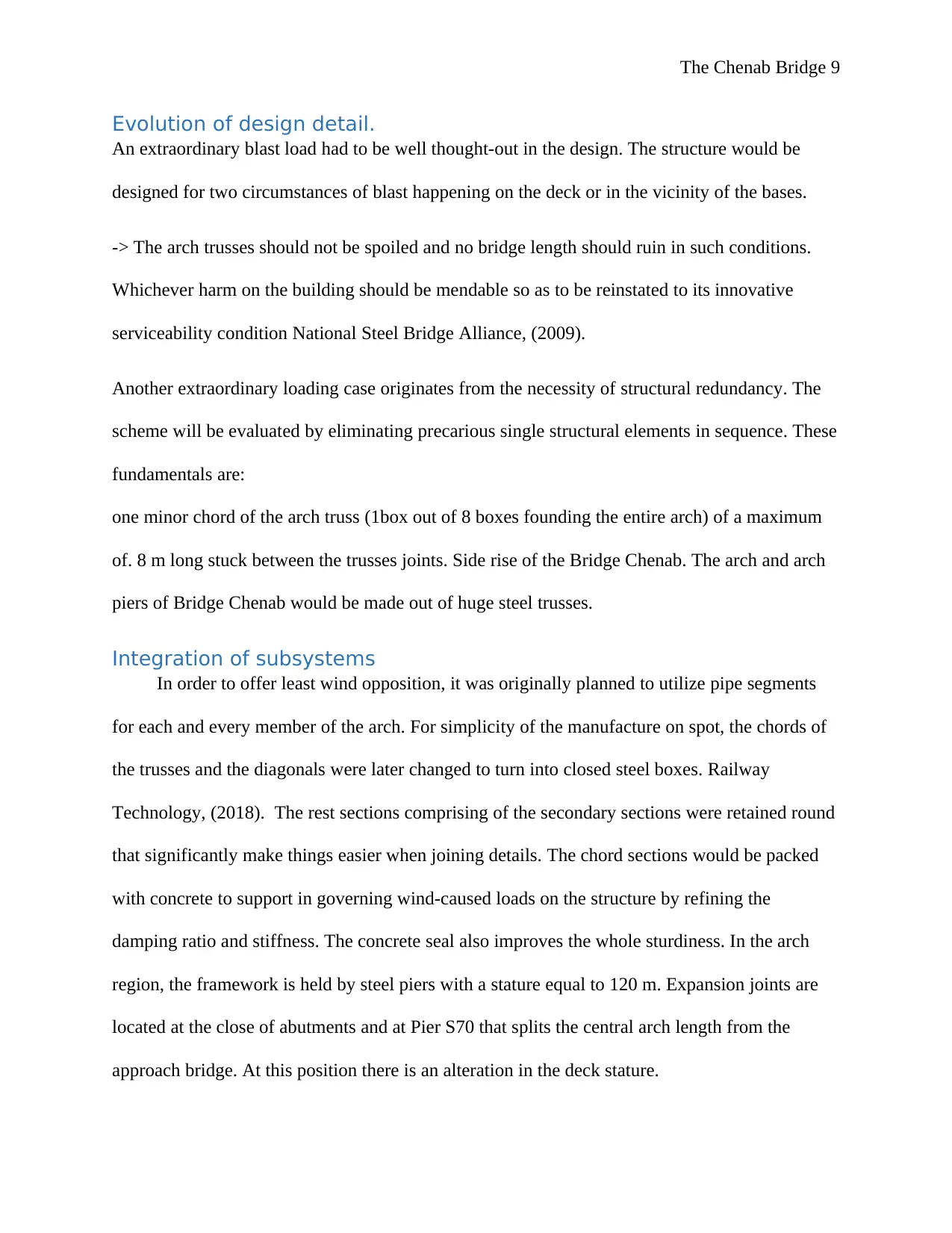
region, the framework is held by steel piers with a stature equal to 120 m. Expansion joints are
located at the close of abutments and at Pier S70 that splits the central arch length from the
approach bridge. At this position there is an alteration in the deck stature.
⊘ This is a preview!⊘
Do you want full access?
Subscribe today to unlock all pages.

Trusted by 1+ million students worldwide
The Chenab Bridge 10
Design tools
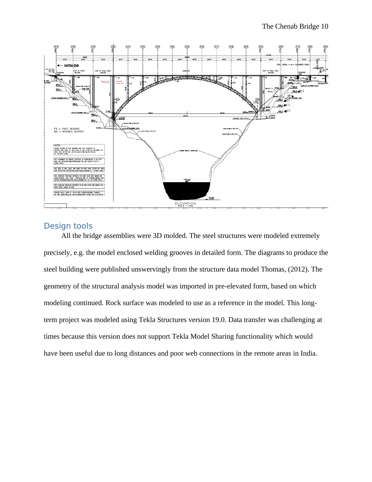
All the bridge assemblies were 3D molded. The steel structures were modeled extremely
precisely, e.g. the model enclosed welding grooves in detailed form. The diagrams to produce the
steel building were published unswervingly from the structure data model Thomas, (2012). The
geometry of the structural analysis model was imported in pre-elevated form, based on which
modeling continued. Rock surface was modeled to use as a reference in the model. This long-
term project was modeled using Tekla Structures version 19.0. Data transfer was challenging at
times because this version does not support Tekla Model Sharing functionality which would
have been useful due to long distances and poor web connections in the remote areas in India.
Paraphrase This Document
Need a fresh take? Get an instant paraphrase of this document with our AI Paraphraser
The Chenab Bridge 11
Railway Technology, (2018)
Evaluation and validation of Chenab Bridge
Evaluation
An all-inclusive evaluation on both deterministic and probabilistic danger analyses was
executed for the Chenab bridge position. The chief conclusions are summarized below:
i) The Chenab bridge setting is located in the tectonically active Himalayan zone falling under
zone IV. Eighty two seismo tectonic topographies such as faults/thrusts were acknowledged that
may cause significant future earthquakes within 350 km radius of the Chenab bridge site.
ii) Out of these tectonic topographies, 20 of them were well thought-out as major and their
source lengths changing from 4.82 to 947.97 km.
iii) Wells and Coppersmith’s (1994) model was utilized to forecast magnitudes (Mw) from the
rupture distances for all faults.
The Chenab Bridge 12
Validation
Slope was designed with surface mapping. Every time the experts progressed to next
bench on sequential critical validation was arranged. The innovative alignment was checked with
designed alignment. If any noticeably variation perceived in alignment concerning designed
alignment it required redesign. The validation of each 5m depth was reiterated at least for first
two sequential statures before proceeding to next level. National Steel Bridge Alliance, (2009).
Conclusion
In the design of the Chenab Bridge, special deliberation on a number of extra special
constraints such as fatigue, composite action, second order effects, and global stability was done.
The Chenab Bridge is the leading, longest-span and the uppermost railway arch bridge
interminably constructed worldwide. Its design presented great trials to the design team, but the
difficulties were even more challenging before the gap between the main arch splits was filled.
⊘ This is a preview!⊘
Do you want full access?
Subscribe today to unlock all pages.

Trusted by 1+ million students worldwide
1 out of 13
Your All-in-One AI-Powered Toolkit for Academic Success.
+13062052269
info@desklib.com
Available 24*7 on WhatsApp / Email
![[object Object]](/_next/static/media/star-bottom.7253800d.svg)
Unlock your academic potential
Copyright © 2020–2026 A2Z Services. All Rights Reserved. Developed and managed by ZUCOL.