Structural Steelwork Design and Optimization
VerifiedAdded on 2020/05/11
|10
|2720
|143
AI Summary
This assignment delves into the world of structural steelwork design. Students will learn about various design methodologies, including limit state theory, and explore how to optimize steel structures for strength and performance. The focus encompasses both theoretical concepts and practical applications, addressing seismic design, connections, and common defects in construction. Safety considerations are emphasized throughout the assignment, highlighting the importance of safe practices on construction sites.
Contribute Materials
Your contribution can guide someone’s learning journey. Share your
documents today.
RUNNING HEAD: STEEL CONSTRUCTION
NAME
UNIT
ASSIGNMENT
ASSESSMENT NUMBER
1
NAME
UNIT
ASSIGNMENT
ASSESSMENT NUMBER
1
Secure Best Marks with AI Grader
Need help grading? Try our AI Grader for instant feedback on your assignments.
RUNNING HEAD: STEEL CONSTRUCTION
Executive Summary:
The project covers the process of construction from the moment the idea is conceived till it is ready
for hand over. It describes in detail the process of construction by analysing the construction costs, the
design considerations, load calculation and structural design, bar selection and designing for shears.
The foundation will also be designed to the AS3600 and from here the write-up of the project
sections, primarily question 2 and 3 explaining the various terms and design components associated
with the project.
2. Design documentation.
The design documentation in this case includes the:
Regulatory Codes and Standards:
Loading (dead and live) refer to AS1170
The designing of structural steel is in adherence to AS4100
Foundations:
The geotechnical engineer has recommended the use screw piles when designing for safe
bearing capacity.
Concrete:
The design of concrete members is done according to AS3600
For steel encasement, mix shall be 1:2:4
21 day cure
Reinforcement
As per the engineer’s recommendation, all bars are to be lapped. Bar sizes to be used include:
N12, N16, N20 and N24
Structural steel
Erection and fabrication of steel members done according to AS1554 and AS4100
The surface of steelwork is done according to AS1627
All steelwork that is not enclosed is to be painted.
Internal protective coating is to be done according to AS1627. The minimum 35um primer to
be used is zinc phosphate.
External protective coating is to be done according to AS1627. This includes the application
of two layers of i.e. alkyd primer and a coat of not more than 50um.
Mega and super-structures have been engineered with cutting-edge methods to provide building
stability, comfy, sustainable, and renewable applications for a desirable life cycle. A wide range of the
construction methods that were in use in earlier generations or eras have been incorporated in the
current trends with changes to increase the structural durability. Portal steel frame systems have been
used during construction since the mid-1900s. The approach assures overall performance in regards to
expenses, time saving, making sure the integrity of the structure. But, the method of construction is
gaining root in the present day construction sector thanks to the capability to withstand as
considerable wind loading affecting the form and stability deal as wind movement end result and
deliver stability of the shape. The elements specializes in assisting with the structural resistance at the
side of the vertical stability of the building when used along with portal frames.
1
RUNNING HEAD: STEEL CONSTRUCTION
The construction of the steel members follows a few standard ways wherein each they are
incorporated at the bottom slab of the event or a casting pad created for a specific phase of the event.
Once the initial concrete has been placed into the long, member, stability in the slabs is ensured by
incorporating steel columns, beams and braces. When this is done, connections can be commenced
from the column to the beams to the trusses and finally the roof. To set them up in place, they can be
carried by use light plant machines, humans but in complex cases crane is used to move the steel
sections to the site, after which they connect with the other steel sections within the construction site
(Kurrer, 2008).
The steel sections’ ability to resist lateral effect of the wind load is contributed to further which is
probably added within the path of the preliminary degrees of building them. Steel rebars can be
introduced to the frame systems to improve the structure of the steel sectionss. It is generally implied
that a well-preferred to use I or H sections for these frames though angle lines can be used as bracing
depending on the dimensions. What’s more is, there are factors or elements of interest for the
crewmembers working in an environment with steel frames that include environmental, which has
wind in order to build the crane risky and consequently the steel section to fall on the personnel
should be noted. Once the section is well bolted and welded, it can be considered sturdy enough to
provide the effective resistance to wind forces (Pessiki and Mlynarczyk, 2003).
Connecting of the members of the steel sectionss in is done with the use of the method of a close fit
joint during which one steel sections is above the next in the link to make a guided joint for each steel
sections. Additionally, joint filling materials location unit used, which might be go with hobby in their
thermal moves, climate resistance, and consequently the structural actions of the constructing once of
completion. Therefore, as the wind blows along the course of one steel sections, the rest of the steel
sections facilitate the support of the member especially as they may be all interconnected, they remain
powerfully established to form a rigid network of support and bracing.
Some of the notable benefits of incorporating steel sections during the construction process is that the
increased rigidity of the structure. The design and production process of the steel sections is done with
the focus of producing steel sections of a particular predetermined weight. The in this case are
designed to be independent systems which offer helpful and rigid bracing support for the whole
system of the building, for this reason they are designed with the steel sections having a double
bracing or welded plate to provide a firmer bracing effect and preserve its stability. Once the steel
sections are ready collectively, extra reinforcement of the steel sections is required to be meshed with
them which is then completed (Yu, 2000).
The use of portal frames with connecting edges of the steel sections is currently a method that a many
cutting-edge companies have adopted. The device of creating the steel sections is discussed above,
and each one of the technical areas pre-described are incorporated to create precision and exactness of
the steel sections (Lam et al., 2013).
In the documentation, there is no geotechnical report or architectural drawing so any discussions made
can only be made in relation to the structural engineering documentation. However the technology at
the moment allows for the designers and contractors to be able to save some time beforehand and
especially in the case of this building, particular attention is given to giving it freely.
The problems experienced during the acquisition of the documentation of these civil engineering
projects:
These are:
The unavailability of public records in the public council sectors.
2

RUNNING HEAD: STEEL CONSTRUCTION
Some of the geotechnical tests conducted in the design and construction have been very
tedious making the obtaining documentation very challenging.
3. Site visit documentation
Site visits are a mandatory construction procedure as they mainly involve going to check out the work
done by a contractor and provide the approvals if need be for the continuation of the job. Site visits
happen either regularly after a predefined interval of time or after the completion of a predetermined
stage of the construction. They comprise members of every party including the client’s, consultant
and contractor’s team who are the project stakeholders (Toole, 2002).
Periodic meetings at the building site are an essential a part of the target meeting objectives of the
entire project. If held regularly, the site meetings happening among the project leads especially when
dealing with an issue can aid in facilitating better information sharing and the joint effort almost
always guarantees that the challenge will be solved or a way around it will be charted. This leads to
the goals being completed efficiently. Challenge in the site can be attributed to poor management with
the key aspect being a lack of proper communication and information management.
As such, it is important to hold the meetings normally and scheduled prior, perhaps on a weekly or
monthly basis, a decision relying on the agendas to be discussed, although at the end of the day, the
scale and complexity of the construction project may prove to require non-standard site meeting
schedule. As such, their purpose will be reporting developments, permitting dialogue when of any
problems or troubles arise, and allowing the proposal of solutions or alternatives. They provide an
opportune possibility for bi-lateral discussions of any issues which have arisen or which are expected
(Mustapha and Naoum, 1999).
For this construction, the latest site visit was conducted on the 10th of October 2017. This was a
monthly meeting meant to periodically check on the progress and discuss about any issues on the
construction site. The meeting conducted prior to this was held 2 weeks before and was not part of the
regular monthly meeting but rather was held to approve the work done on the completion of the third
phase of the steel truss assembly. So far, 7 meetings have been held, both monthly and at the end of
every phase.
An amalgamation of the reports of all site visits indicate the few agendas have included administrative
changes, end phase approval, cost analysis, stock taking of machinery and tools, quantity
measurements and issuing of payment certificates. So far, defects observed have been either rectified
or ignores. The specifications have also been modified over these site meetings. Over the last site
meeting, photographs were taken to compliment the written reports so as to enable further discussion
and deliberation. In this meeting, matters to be discussed included:
I. The steel beam member on the western section of the structure that has been affected by the
torsional turning moment due to wind loading giving it a slight twist. The turn is not clearly
visible from afar and one would need to observe closely. It was agreed that it would not have
any effect on the integrity of the structure and could therefore be left as is.
II. The additional bolts connecting the steel column section to the trusses over the welded plate
and brace. This was agreed on as the wind loading on the site had surpassed the expected
wind loading values.
III. Alteration of the specifications to allow for a sturdier roofing system. While part of the roof
had been constructed, it was agreed on that the specifications are to be revised to provide for a
an extra set of truss members to help counter the unexpected wind loading.
• In the photos taken, most structural members are as described with the exception of a few which
have been modified to adapt to conditions on the site. The steel rafter connections are modified to
contain an extra two bolts each because of the excessive and unexpected wind load which was only
noticed after the design.
3
Secure Best Marks with AI Grader
Need help grading? Try our AI Grader for instant feedback on your assignments.

RUNNING HEAD: STEEL CONSTRUCTION
Figure 1: Steel truss/rafter on site.
In trying to keep the members as close to the design as possible, the rest of the components have been
left as is.
4
Figure 1: Steel truss/rafter on site.
In trying to keep the members as close to the design as possible, the rest of the components have been
left as is.
4

RUNNING HEAD: STEEL CONSTRUCTION
Steel truss detail
Figure 2: Steel truss detail.
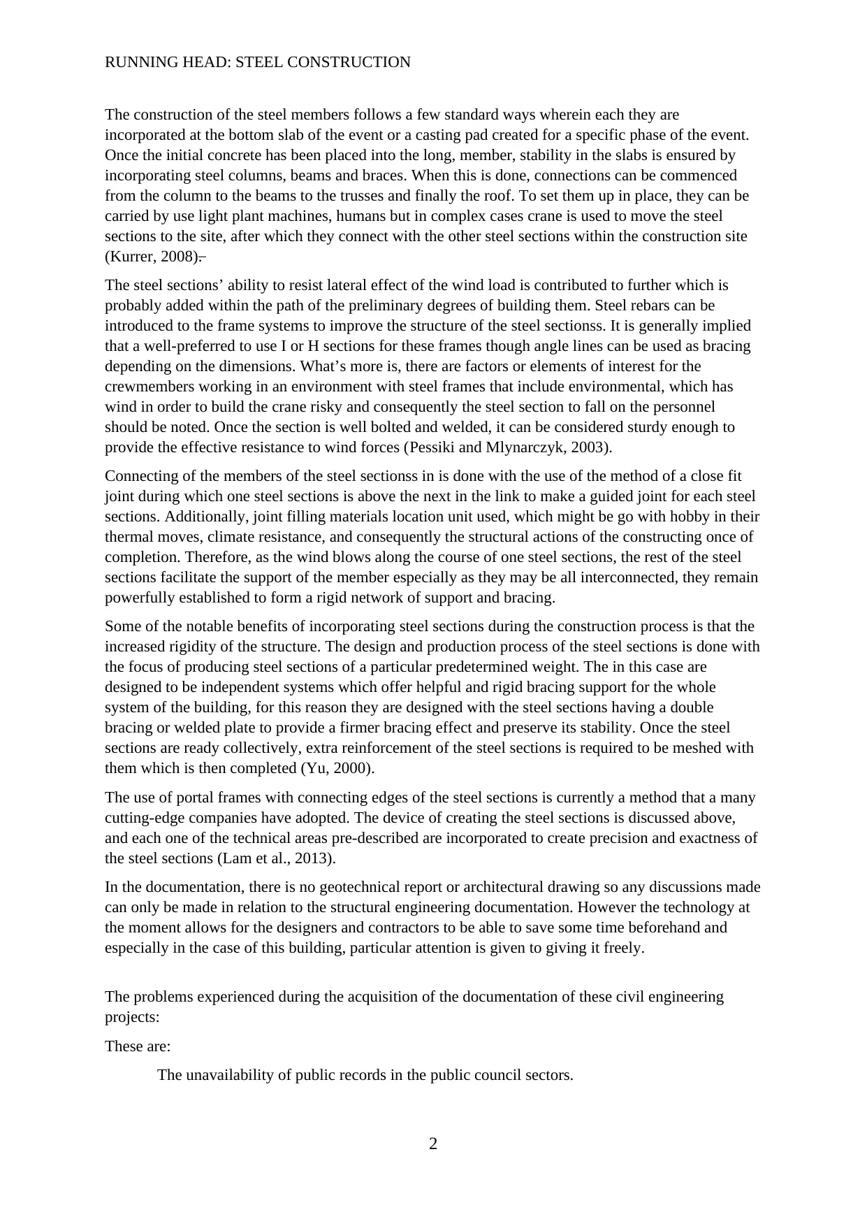
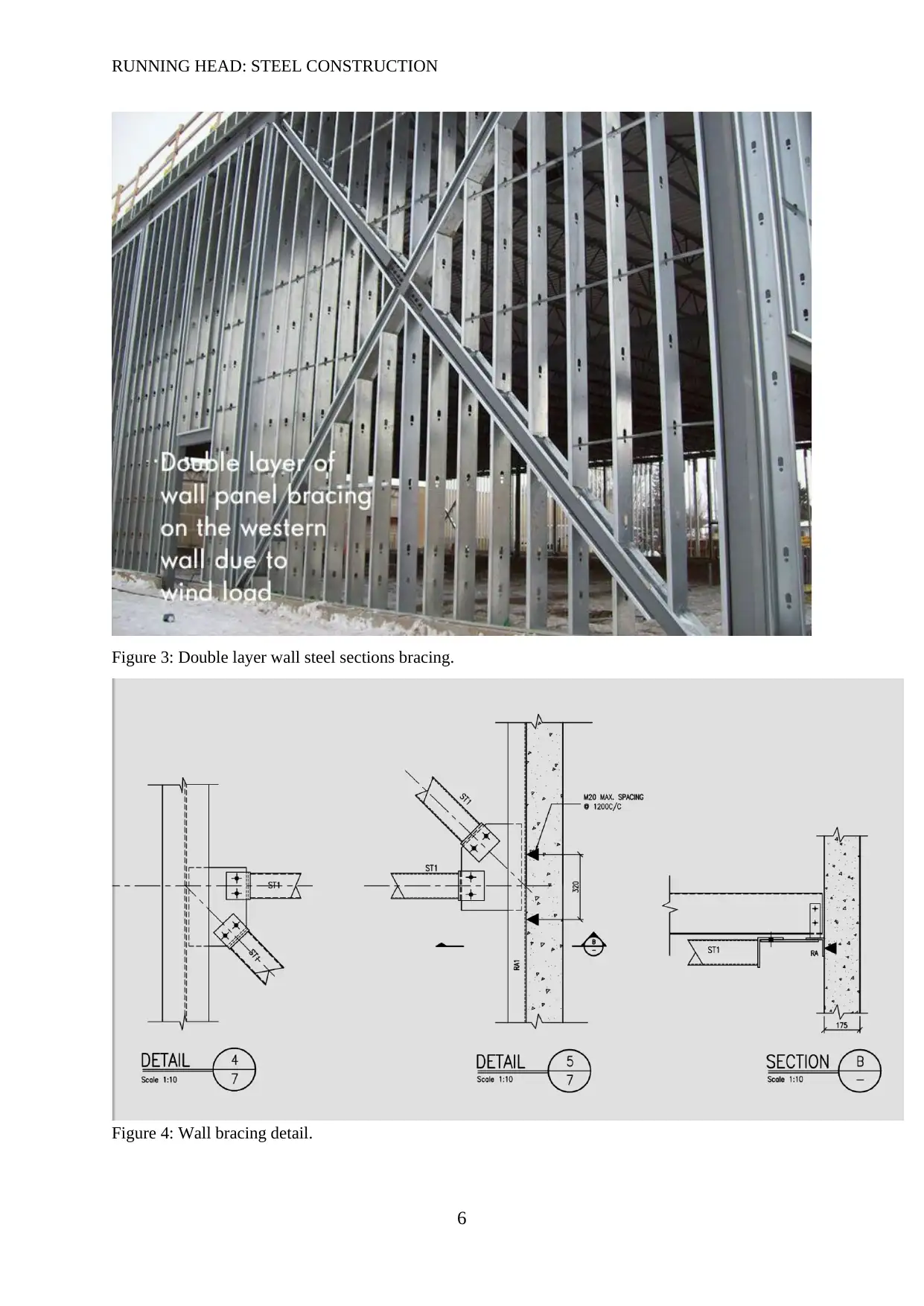
Wall steel sectionss have also been modified a bit to include an extra layer of steel bracing on the
Western side as that is the most affected side of the building. Their bracings have, however remained
in alignment with each other in an effort to minimize any adverse design differences.
5
Steel truss detail
Figure 2: Steel truss detail.
Wall steel sectionss have also been modified a bit to include an extra layer of steel bracing on the
Western side as that is the most affected side of the building. Their bracings have, however remained
in alignment with each other in an effort to minimize any adverse design differences.
5
RUNNING HEAD: STEEL CONSTRUCTION
Figure 3: Double layer wall steel sections bracing.
Figure 4: Wall bracing detail.
6
Figure 3: Double layer wall steel sections bracing.
Figure 4: Wall bracing detail.
6
Paraphrase This Document
Need a fresh take? Get an instant paraphrase of this document with our AI Paraphraser
RUNNING HEAD: STEEL CONSTRUCTION
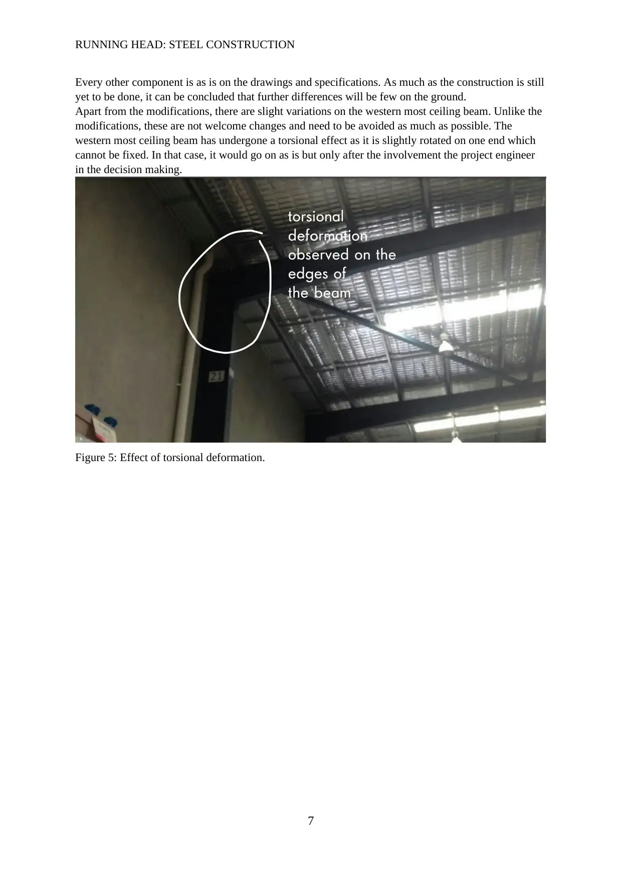
Every other component is as is on the drawings and specifications. As much as the construction is still
yet to be done, it can be concluded that further differences will be few on the ground.
Apart from the modifications, there are slight variations on the western most ceiling beam. Unlike the
modifications, these are not welcome changes and need to be avoided as much as possible. The
western most ceiling beam has undergone a torsional effect as it is slightly rotated on one end which
cannot be fixed. In that case, it would go on as is but only after the involvement the project engineer
in the decision making.
Figure 5: Effect of torsional deformation.
7
RUNNING HEAD: STEEL CONSTRUCTION
References:
AustralianStandards.com.au: The Leading Australian Standard Site on the Net. 2013.
AustralianStandards.com.au: The Leading Australian Standard Site on the Net. [ONLINE] Available
at: http://www.australianstandards.com.au/. [Accessed 10 October 2014]
Barrie, D.S. and Paulson, B.C., 1992. Professional construction management: including CM, design-
construct, and general contracting. McGraw-Hill Science/Engineering/Math.
Construction work code of practice, 2012, Viewed October 10 2014,
<http://www.safeworkaustralia.gov.au/sites/swa/model-whs-laws/model-COP/Documents/Historical
%20model%20Codes%20of%20Practice/Construction-Work-V1.doc>.
Chau, K.W. and Anson, M., 2002. A knowledge-based system for construction site level facilities
layout. Developments in Applied Artificial Intelligence, pp.25-67.
Chen, Z., Ge, H., Kasai, A. and Usami, T., 2007. Simplified seismic design approach for steel portal
frame piers with hysteretic dampers. Earthquake engineering & structural dynamics, 36(4), pp.541-
562.
Da Silva, J.G.S., De Lima, L.R.O., Vellasco, P.D.S., De Andrade, S. and De Castro, R.A., 2008.
Nonlinear dynamic analysis of steel portal frames with semi-rigid connections. Engineering
Structures, 30(9), pp.2566-2579.
Degertekin, S.O., 2008. Optimum design of steel frames using harmony search algorithm. Structural
and multidisciplinary optimization, 36(4), pp.393-401.
Josephson, P.E. and Hammarlund, Y., 1999. The causes and costs of defects in construction: A study
of seven building projects. Automation in construction, 8(6), pp.681-687.
Kurrer, K.E., 2008. The history of the theory of structures: from arch analysis to computational
mechanics. International Journal of Space Structures, 23(3), pp.193-197.
Lam, D., Ang, T.C. and Chiew, S.P., 2013. Structural steelwork: design to limit state theory. Crc
Press.
Liu, M., Burns, S.A. and Wen, Y.K., 2005. Multiobjective optimization for performance‐based
seismic design of steel moment frame structures. Earthquake Engineering & Structural Dynamics,
34(3), pp.289-306.
8

RUNNING HEAD: STEEL CONSTRUCTION
Mahfouz, S.Y., 1999. Design optimization of structural steelwork (Vol. 318). University of Bradford.
Mustapha, F.H. and Naoum, S., 1998. Factors influencing the effectiveness of construction site
managers. International Journal of Project Management, 16(1), pp.1-8.
Nethercot, D., 2001. Limit states design of structural steelwork. CRC Press.
Pessiki, S. and Mlynarczyk, A., 2003. Experimental evaluation of the composite behavior of precast
concrete sandwich wall steel sectionss. PCI journal, 48(2), pp.54-71.
Toole, T.M., 2002. Construction site safety roles. Journal of Construction Engineering and
Management, 128(3), pp.203-210.
Wrzesien, A., Lim, J.B. and Nethercot, D.A., 2012. Optimum joint detail for a general cold-formed
steel portal frame. Advances in Structural Engineering, 15(9), pp.1623-1639.
Yu, W.W., 2000. Cold-formed steel design. John Wiley & Sons.
9
1 out of 10
Related Documents


Your All-in-One AI-Powered Toolkit for Academic Success.
+13062052269
info@desklib.com
Available 24*7 on WhatsApp / Email
![[object Object]](/_next/static/media/star-bottom.7253800d.svg)
Unlock your academic potential
© 2024 | Zucol Services PVT LTD | All rights reserved.