Detailed Design of Portal Frame Structure for Civil Project
VerifiedAdded on 2023/04/21
|31
|3984
|259
Project
AI Summary
This civil engineering project focuses on the comprehensive design of a portal frame structure, commonly used in single-story buildings. It covers various aspects, starting with an introduction to steel portal frames and their applications. The project includes a detailed structural design analysis, encompassing roof and beam design, universal column design, and cladding installation. It further delves into connection designs, addressing roof panel connections, cold-formed steel connections to the main beam, and beam-to-column bolt details. The foundation design section explores reinforced concrete wall design and slab floor design, considering material properties and actions. Additionally, the project incorporates drainage design and hard standing area design. Drawings, including site plans and roof plans, are provided to illustrate the design. This document offers a complete overview for students and professionals in civil engineering, available on Desklib for further study and reference.
CIVIL ENGINEERING
By Name
Course
Instructor
Institution
Location
Date
By Name
Course
Instructor
Institution
Location
Date
Paraphrase This Document
Need a fresh take? Get an instant paraphrase of this document with our AI Paraphraser
1.0 INTRODUCTION
It is evaluated that half of all constructional steelwork utilized in the UK is in the essential
structure of single-story structures. Inside this significant market division, the steel portal frame
has turned into the most widely recognized auxiliary shape in pitched rooftop structures, in light
of its economy and adaptability for a wide scope of ranges(Shaw 2013). In spite of the fact that
the utilization of steel portal frame is settled in the UK, there is no production which characterizes
best practice in this type of development. The direction in this production focuses on the structure
of single-span portal frame utilizing cold formed steel I areas, however the general standards
additionally apply to multi-range portal frames and to the utilization of manufactured segments.
Where conceivable, the direction given has been concurred with fashioners, steelwork temporary
workers and those worried about checking for building control purposes(Papadopoulos, Soimiris
and Papadrakakis 2013).
It manages the issues that happen sensibly frequently in configuration practice and which are
agreeable to general direction. Perspectives required for idea or primer configuration are secured
first, trailed by more subtleties for definite plan. Auxiliary components, for example, purlins, end
peaks and cladding are additionally assessed. The utilization of PC configuration has made
manual computations nearly repetitive for normal portal frames, and in this manner point by point
direction on manual techniques for examination is excluded. Be that as it may, tables and graphs
for starter configuration are displayed, and reference is made to different distributions for manual
examination systems.
Yield from the CSC Fastrak program is incorporated into Supplement D, as this program is
broadly utilized by steel fabricators in the UK. Where direction is given in detail somewhere else,
for instance on the plan of entry outlines in flame limit conditions, built up productions are
alluded to, with a concise clarification and survey of their substance. Cross-reference is made to
the pertinent conditions of BS 5950-1:2000[1]. The alteration of BS 5950-1 from the 1990
adaptation to the 2000 rendition gave ascend to some specialized changes that influence the
structure of portal frames. Too, statements were renumbered in the 2000 form. The primary
design that effect point by point structure of portal frame are as per the discussion.
2.0 Scope of the work
This particular work was limited to the design of the portal frame structure that has various
functional characteristics and subsequent analysis of the performance of these components.
3.0 Structure design
3.1 Overall Analysis of portal frame
The portal frames are generally regarded as low-rise structures that are made of columns and
rafters that are horizontal which are connected by the moment-resisting connections. The frame
actually relies on the bending resistance of the very connections. These connections are stiffened
by a favorable haunch or sections that are deepened. This leads to the formation of the rigid frame
that constitutes the structure. The frames are actually stable in their own plane and assist in the
provision of the clear plan. Various sorts of structure can be characterized comprehensively as
entrance outlines.
These are depicted quickly in this section; however the consequent Sections of this production
focus on the structure of single-range symmetric portal frame. All the casing types portrayed can
be intended for a scope of base fixity; determination of fitting fixity is an imperative structure
choice. Ostensibly stuck base is the most widely recognized for comfort of establishment
structure and development. It may not give the most financial aggregate answer for establishment
⊘ This is a preview!⊘
Do you want full access?
Subscribe today to unlock all pages.
Trusted by 1+ million students worldwide
and structure in light of the fact that even unassuming base solidness regularly gives real
enhancements in casing dependability. The data given with respect to ranges, rooftop pitch, and
so forth is run of the mill of the structure that are represented.
3.2 Roof Design
A portal frame that has been designed will basically have a pitched roof with the following
dimensions
A span that ranges between 50-60m
Height of the eaves as 10m
Roof pitch as 6 degrees
Frame spacing was taken as 5 m
Having haunches in the rafters at the apex and eaves.
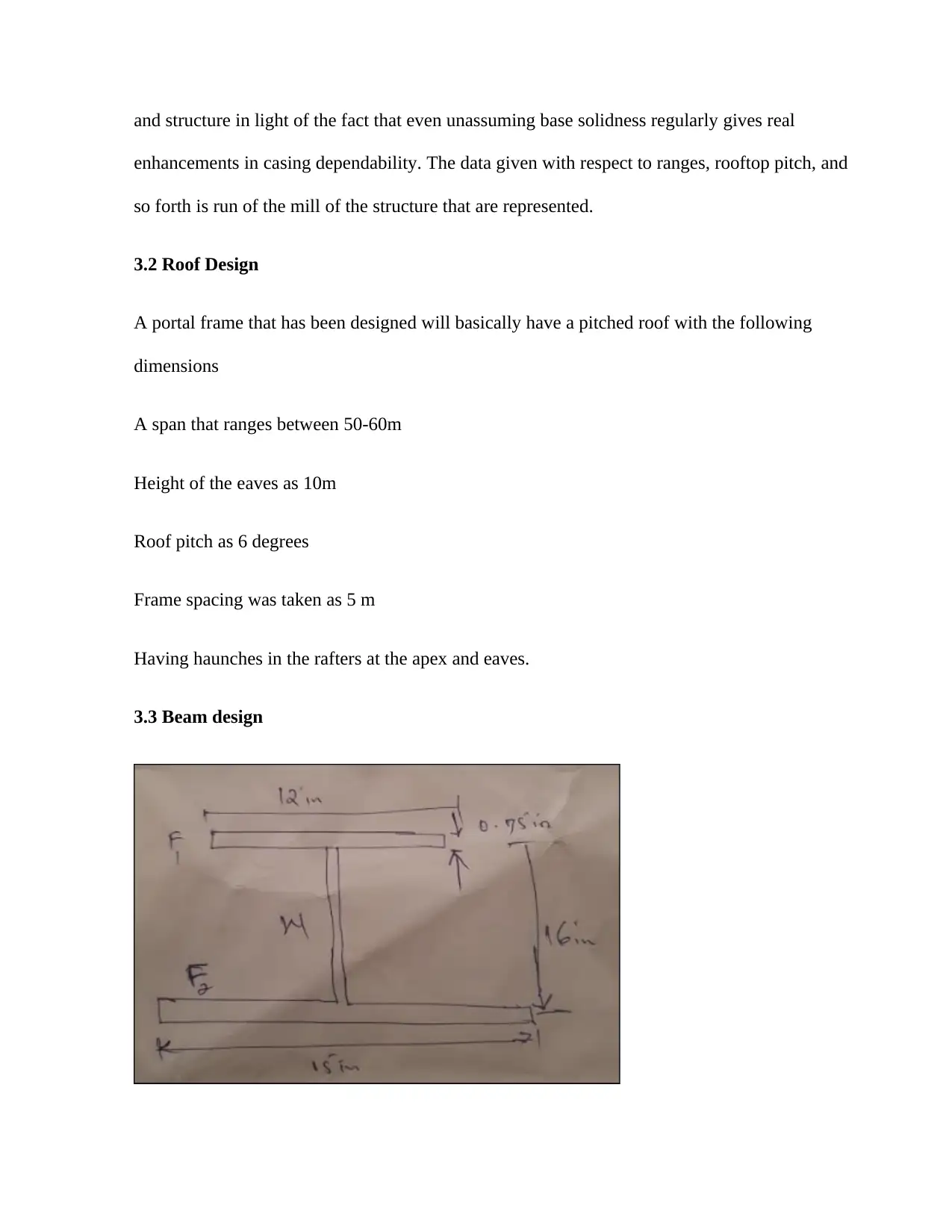
3.3 Beam design
enhancements in casing dependability. The data given with respect to ranges, rooftop pitch, and
so forth is run of the mill of the structure that are represented.
3.2 Roof Design
A portal frame that has been designed will basically have a pitched roof with the following
dimensions
A span that ranges between 50-60m
Height of the eaves as 10m
Roof pitch as 6 degrees
Frame spacing was taken as 5 m
Having haunches in the rafters at the apex and eaves.
3.3 Beam design
Paraphrase This Document
Need a fresh take? Get an instant paraphrase of this document with our AI Paraphraser
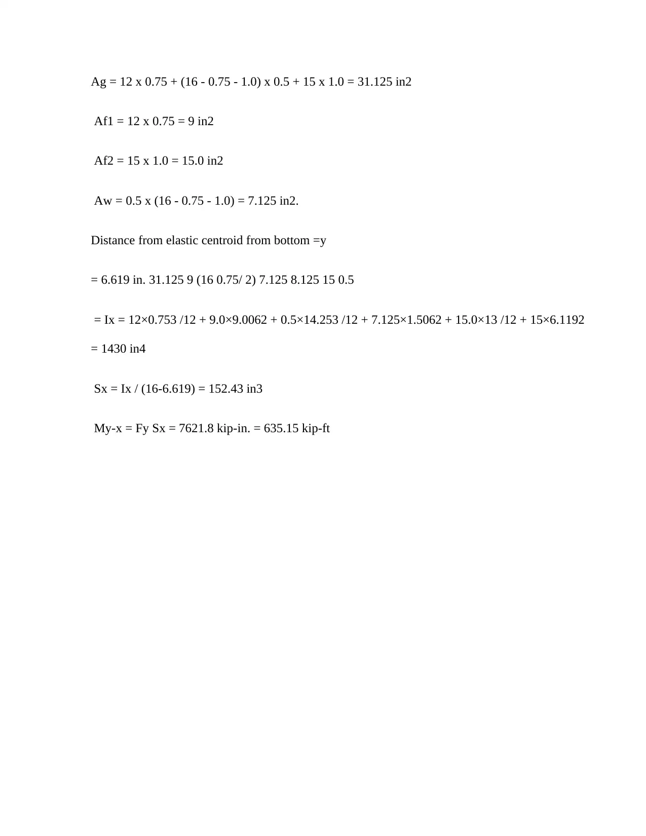
Ag = 12 x 0.75 + (16 - 0.75 - 1.0) x 0.5 + 15 x 1.0 = 31.125 in2
Af1 = 12 x 0.75 = 9 in2
Af2 = 15 x 1.0 = 15.0 in2
Aw = 0.5 x (16 - 0.75 - 1.0) = 7.125 in2.
Distance from elastic centroid from bottom =y
= 6.619 in. 31.125 9 (16 0.75/ 2) 7.125 8.125 15 0.5
= Ix = 12×0.753 /12 + 9.0×9.0062 + 0.5×14.253 /12 + 7.125×1.5062 + 15.0×13 /12 + 15×6.1192
= 1430 in4
Sx = Ix / (16-6.619) = 152.43 in3
My-x = Fy Sx = 7621.8 kip-in. = 635.15 kip-ft
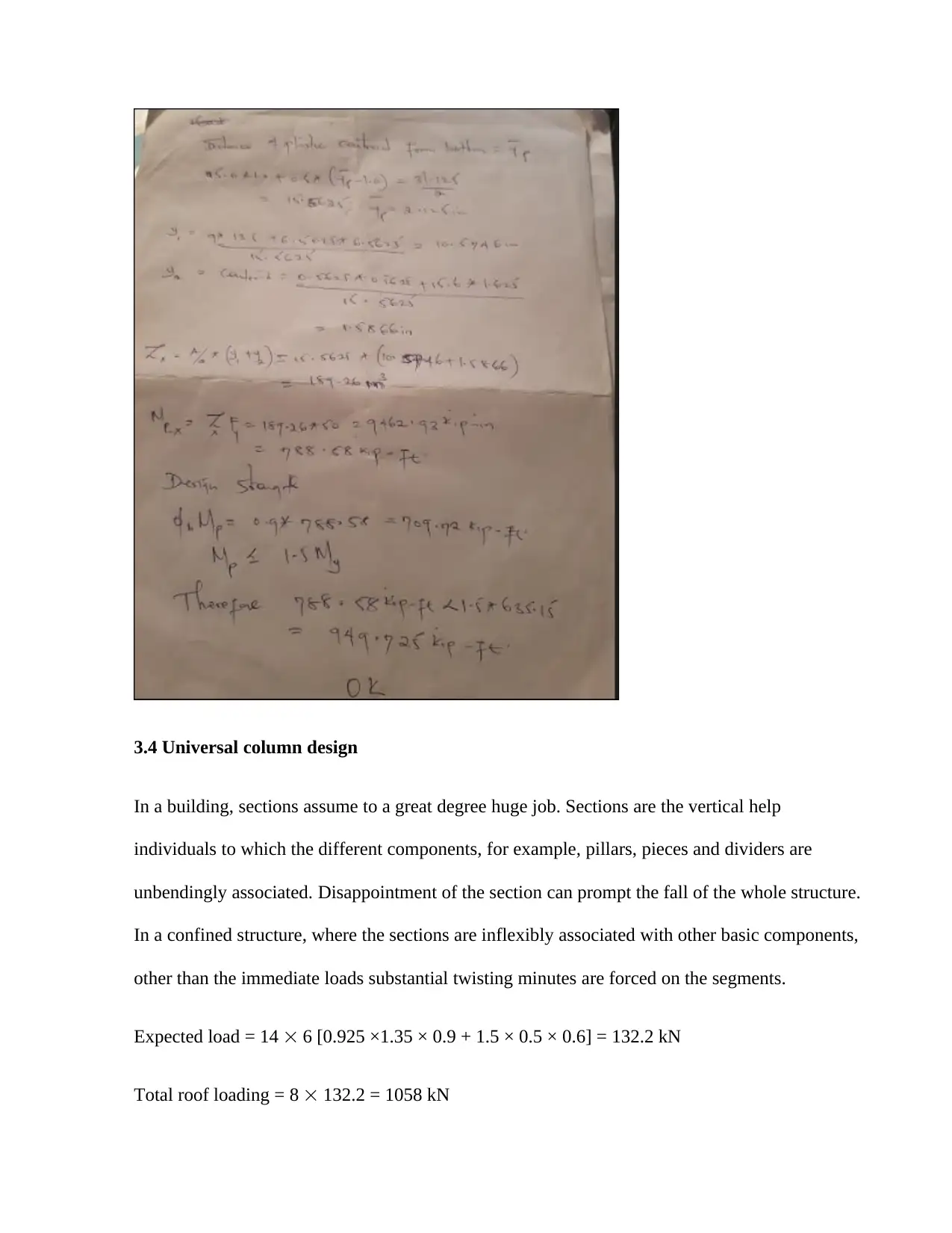
3.4 Universal column design
In a building, sections assume to a great degree huge job. Sections are the vertical help
individuals to which the different components, for example, pillars, pieces and dividers are
unbendingly associated. Disappointment of the section can prompt the fall of the whole structure.
In a confined structure, where the sections are inflexibly associated with other basic components,
other than the immediate loads substantial twisting minutes are forced on the segments.
Expected load = 14 6 [0.925 ×1.35 × 0.9 + 1.5 × 0.5 × 0.6] = 132.2 kN
Total roof loading = 8 132.2 = 1058 kN
⊘ This is a preview!⊘
Do you want full access?
Subscribe today to unlock all pages.
Trusted by 1+ million students worldwide
Equivalent horizontal force (acting as a point load) at roof level in end frame = 0.5 0.5%
1058 = 2.7 kN gk = 0.9 kN/m2 qk = 0.6 kN/m2 (see arrangement and actions)
Resultant horizontal force at roof level = 2.7 kN 5.3.2(3)
Floor loading on one column = 14 6 [0.925 ×1.35 3.7 + 1.5 × 0.7 3.3] = 679 kN
Total floor loading = 8 679 = 5433 kN
Equivalent horizontal force (acting as a point load) at each floor level in end frame = 0.5 0.5%
5433 = 13.6 kN.
13.6KN>12.97 thus OK.
3.5 Cladding of wall installation
Liner sheets are generally made from chilly shaped pre-covered steel or aluminum and have a
shallow trapezoidal profile, i.e. a stature 18mm to 20mm as delineated underneath. For steel
liners, the sheet thickness is generally either 0.4mm or 0.7mm, while aluminum liner sheets are
marginally thicker at 0.5mm or 0.9mm. The decision of liner will rely upon the required crossing
ability, the cladding establishment technique and the acoustic prerequisites of the cladding. Where
required, the acoustic execution of the cladding, specifically its capacity to retain sound and limit
resonation, might be upgraded by the utilization of a punctured liner sheet(Narayanan 2014).
The shallow liner sheets are not sufficiently able to stroll on, so it is basic that the protection,
spacer framework and climate sheet are introduced from sheets or access stages, as showed
beneath. Notwithstanding, they do give a non- delicate boundary against falling once they have
been completely secured. Where strolling access is required, usually practice to supplant the
Paraphrase This Document
Need a fresh take? Get an instant paraphrase of this document with our AI Paraphraser
shallow liner profile with an increasingly considerable sheet, i.e. 32mm to 35mm trapezoidal
profile in 0.7mm measure steel.
3.6 Design Of Access Door
The access door will have dimensions of double 1000x2045.This will be equivalent to dimension
of two room doors.
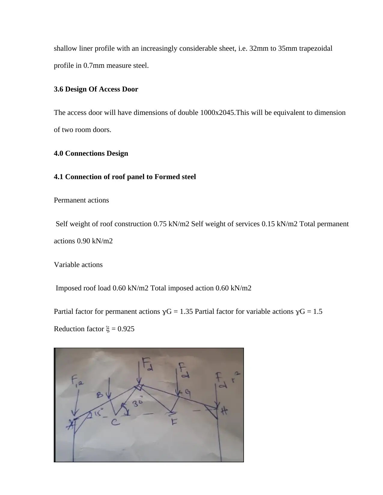
4.0 Connections Design
4.1 Connection of roof panel to Formed steel
Permanent actions
Self weight of roof construction 0.75 kN/m2 Self weight of services 0.15 kN/m2 Total permanent
actions 0.90 kN/m2
Variable actions
Imposed roof load 0.60 kN/m2 Total imposed action 0.60 kN/m2
Partial factor for permanent actions G = 1.35 Partial factor for variable actions G = 1.5
Reduction factor = 0.925
profile in 0.7mm measure steel.
3.6 Design Of Access Door
The access door will have dimensions of double 1000x2045.This will be equivalent to dimension
of two room doors.
4.0 Connections Design
4.1 Connection of roof panel to Formed steel
Permanent actions
Self weight of roof construction 0.75 kN/m2 Self weight of services 0.15 kN/m2 Total permanent
actions 0.90 kN/m2
Variable actions
Imposed roof load 0.60 kN/m2 Total imposed action 0.60 kN/m2
Partial factor for permanent actions G = 1.35 Partial factor for variable actions G = 1.5
Reduction factor = 0.925
Reaction force at support A RA =2 Fd = 87.8 kN
At joint A FAB sin15o + (RA-W/2) = 0 FAB cos15o + FAC = 0 FAB = –255 kN FAC =
246 kN .
At joint B FBC + W cos15o = 0 FBD - FAB - W sin15o = 0 FBC = –42 kN FBD = –243 kN
At joint C FBC sin75o + FCD sin30o = 0 FCE – FAC - FBC cos75o + FCD cos30o = 0
FCD = 82 kN FCE = 164 kN.
4.2 Connection of cold formed steel to main beam
Vertical shear resistance of the composite beam is: 3 M0 v y pl,Rd pl,a,Rd A f V V BS
EN 1993-1-1 6.2.6(3) For rolled I and H sections loaded parallel to the web: A 2bt t t 2r v
f f w but not less than w h t 2800 (2 101.6 6.8) 6.8 5.7 (2 7.6) Av Av
1560 mm2 1.0 (Conservatively from note to 6.2.6(3)) h wt w 1.0 240.4 5.7 1370
mm2 1560 mm2 > 1370 mm2 Therefore, Av 1560 mm2 10 247 3 1.0 275 1560 -3 pl,Rd
V kN Design vertical shear resistance Vpl,Rd = 247 kN 0.31 247 76.5 pl,Rd Ed V < 1.0
In this way the plan protection from vertical shear is satisfactory. Structure opposition for vertical
shear is sufficient 6.2.2.4 As there is no shear compel at the purpose of most extreme bowing
minute (mid range) no decrease (because of shear) in bowing obstruction is required.
4.3 Beams to Column
⊘ This is a preview!⊘
Do you want full access?
Subscribe today to unlock all pages.
Trusted by 1+ million students worldwide
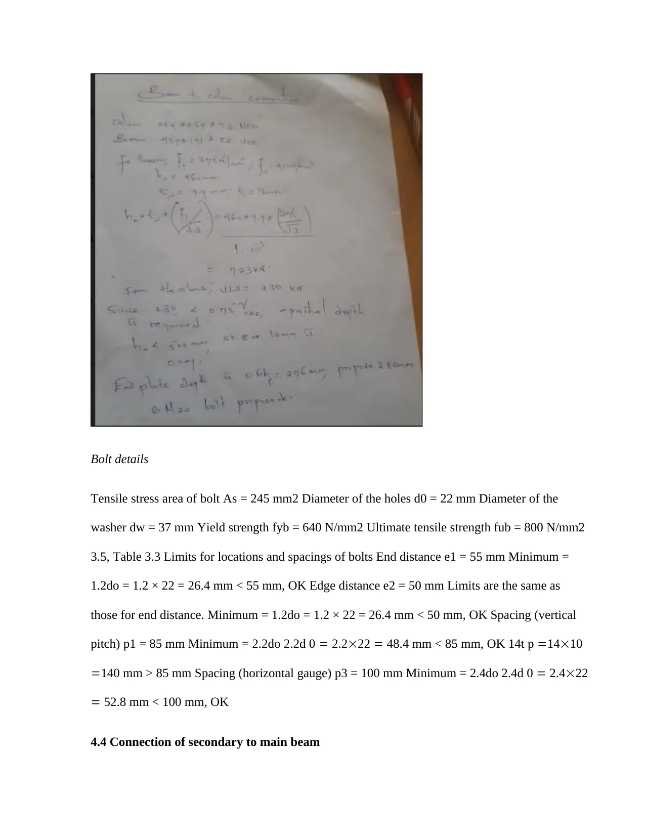
Bolt details
Tensile stress area of bolt As = 245 mm2 Diameter of the holes d0 = 22 mm Diameter of the
washer dw = 37 mm Yield strength fyb = 640 N/mm2 Ultimate tensile strength fub = 800 N/mm2
3.5, Table 3.3 Limits for locations and spacings of bolts End distance e1 = 55 mm Minimum =
1.2do = 1.2 × 22 = 26.4 mm < 55 mm, OK Edge distance e2 = 50 mm Limits are the same as
those for end distance. Minimum = 1.2do = 1.2 × 22 = 26.4 mm < 50 mm, OK Spacing (vertical
pitch) p1 = 85 mm Minimum = 2.2do 2.2d 0 2.222 48.4 mm < 85 mm, OK 14t p 1410
140 mm > 85 mm Spacing (horizontal gauge) p3 = 100 mm Minimum = 2.4do 2.4d 0 2.422
52.8 mm < 100 mm, OK
4.4 Connection of secondary to main beam
Paraphrase This Document
Need a fresh take? Get an instant paraphrase of this document with our AI Paraphraser
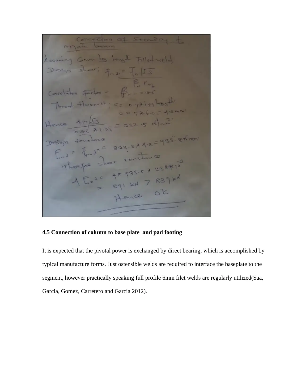
4.5 Connection of column to base plate and pad footing
It is expected that the pivotal power is exchanged by direct bearing, which is accomplished by
typical manufacture forms. Just ostensible welds are required to interface the baseplate to the
segment, however practically speaking full profile 6mm filet welds are regularly utilized(Saa,
Garcia, Gomez, Carretero and Garcia 2012).
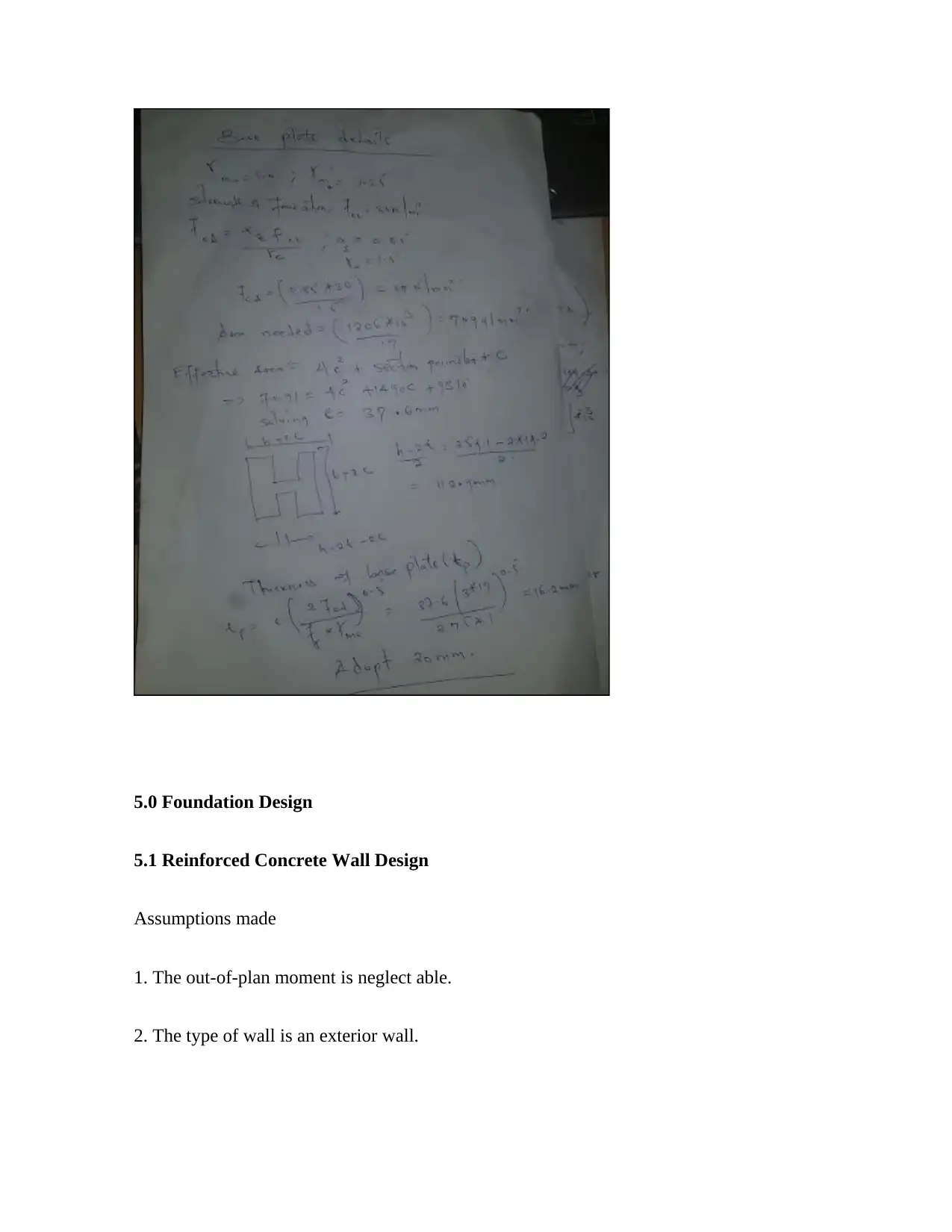
5.0 Foundation Design
5.1 Reinforced Concrete Wall Design
Assumptions made
1. The out-of-plan moment is neglect able.
2. The type of wall is an exterior wall.
5.1 Reinforced Concrete Wall Design
Assumptions made
1. The out-of-plan moment is neglect able.
2. The type of wall is an exterior wall.
⊘ This is a preview!⊘
Do you want full access?
Subscribe today to unlock all pages.
Trusted by 1+ million students worldwide
1 out of 31
Your All-in-One AI-Powered Toolkit for Academic Success.
+13062052269
info@desklib.com
Available 24*7 on WhatsApp / Email
![[object Object]](/_next/static/media/star-bottom.7253800d.svg)
Unlock your academic potential
Copyright © 2020–2025 A2Z Services. All Rights Reserved. Developed and managed by ZUCOL.