Civil Engineering Technology Report: Earthworks, Safety and Design
VerifiedAdded on 2022/12/15
|17
|3603
|73
Report
AI Summary
This comprehensive report delves into the core principles of civil engineering technology. It begins by explaining the methods and techniques employed in earthworks, detailing processes such as excavation, levelling, and filling, as well as the machinery used. The report then explores substructures, covering various foundation types like individual footings, combined footings, strip foundations, raft foundations, pile foundations, and drilled shafts. A significant portion is dedicated to presenting a safety plan, including risk assessment and method statements for civil engineering activities. The report also evaluates a civil engineering problem, proposing a practical solution, and concludes with a design proposal for a new infrastructure project, providing a complete overview of civil engineering concepts and their practical applications. The report is a valuable resource for students seeking to understand the fundamentals of civil engineering and its practical applications.
Running head: CIVIL ENGINEERING TECHNOLOGY
Civil Engineering Technology
Name
Institutional Affiliation
Civil Engineering Technology
Name
Institutional Affiliation
Paraphrase This Document
Need a fresh take? Get an instant paraphrase of this document with our AI Paraphraser
CIVIL ENGINEERING TECHNOLOGY 2
Table of Content
Executive Summary...................................................................................................................3
Explain the methods and techniques used in civil engineering for earthworks and
substructures...............................................................................................................................4
Earthworks..............................................................................................................................4
Excavation..........................................................................................................................4
Levelling.............................................................................................................................4
Cut to Cross Fill..................................................................................................................5
U-Cut..................................................................................................................................5
Loading, hauling and unloading.........................................................................................6
Filling..................................................................................................................................6
Substructure............................................................................................................................7
Foundations............................................................................................................................7
Individual footing...............................................................................................................7
Combined footing...............................................................................................................8
Strip foundation..................................................................................................................8
Raft Foundation..................................................................................................................8
Pile foundation....................................................................................................................9
Drilled shafts.......................................................................................................................9
Present a safety plan risk assessment and method statement for a given civil engineering
activity.....................................................................................................................................10
Evaluate a given civil engineering problem and propose a solution.................................12
Civil Engineering Problem...................................................................................................12
Solution.................................................................................................................................13
Prepare a design proposal for a new infrastructure project..............................................14
Design Proposal....................................................................................................................14
References...............................................................................................................................15
CIVIL ENGINEERING TECHNOLOGY 3
Executive Summary
Earthworks are processes that involve the movement of soil or the stone below the
ground level in order to give way for the setting up of structures. Earthworks give way for the
setting out and construction of foundations. There are different types of foundation and the
choice of foundation to implement depends on the type of soil and size of structure to be
carried. For any civil construction works, there should be a risk assessment plan whose main
motive is to mitigate any accidents that may affect normal site operations. On the part of civil
problems, calculation of structural works and the manufacture of material seem to be
different from one country to another thus making it not easy to operate smoothly in another
country. Constants and safety codes should be made uniform thus making it easy for engineer
to work anywhere. Finally, setting up footbridges in place of slow bumps and zebra crossing
points is a very good civil project since it will help in the reduction of traffic snarl ups
Explain the methods and techniques used in civil engineering for earthworks and
substructures
Earthworks
Earthworks are an engineering process which involves the moving of huge chunks of
soil or movement of rocks and stone structure with the aim of achieving a desired topography
(Correia, 2012). This procedure on the earth surface was made possible by the invention of
the earth-moving machinery (Correia, 2012). This process normally involves the use of very
heavy machinery due to the huge volumes of materials need to be moved. The machines that
are used include; bulldozer, dump truck, dragline excavator, loader and a grader among
several others (Liu & Lu, 2014). Earthwork involves the following processes; measuring and
calculation of volumes, excavation, loading, hauling and unloading and finally filling.
Measuring and Calculation of Volumes
⊘ This is a preview!⊘
Do you want full access?
Subscribe today to unlock all pages.

Trusted by 1+ million students worldwide
CIVIL ENGINEERING TECHNOLOGY 4
There are two main ways of determining the volumes. They include; utilizing the
traditional method for estimating the dimensions with a levelling instrument and attracting
the cross-area to scale (Zdravkovic, Potts, & John, 2011). The volume would then be able to
be determined. The other way is through utilizing the slotting technique which empowers the
estimations to be taken with a ruler or tape on the cut itself.
Excavation
This is basically the removal of the soil from its common, in situ, organize. This process is
divided into 4 types namely; levelling, cut to cross fill, U-cut and finally borrow (Correia,
2012).
Levelling
Levelling is best done with diggers, rakes and scoops as the soil just must be moved over
short distances (Ahern, 2010). The protuberances and edges are cut and the soil is raked,
pushed or tossed into the openings and sorrows with the scraper (Bures, Svabensky, & Vitula,
2011). Profound gaps ought to be compacted with hand-rammers after they have been filled.
Cut to Cross Fill
The soil is exhumed from one side of the street and utilized as fill material at the other
(Schwendicke, et al., 2018). On the off chance that the exhumed soil isn't utilized, it will ruin,
for example it is dumped outside the bank. Cut to cross fill is a viable type of adjusting cut
and fill in moving territory without long haulage (Schwendicke, et al., 2018). In hilly territory
where the cross fall is extremely steep, the fill divide is probably going to be insecure thus it
will be important to cut the entire street into the slope.
Paraphrase This Document
Need a fresh take? Get an instant paraphrase of this document with our AI Paraphraser
CIVIL ENGINEERING TECHNOLOGY 5
Where such sections are experienced, the street width is generally decreased to the
base standard width and as opposed to working up a camber formation; the street will be very
raised towards the slope (Schwendicke, et al., 2018). This gives some wellbeing to vehicles
when the road surface is slippery.
U-Cut
The U-cut is a cut which is generally moulded as a U. The street is sliced through for
example a hillcrest, so as to diminish the inclination (Cubrinovski & McCahon, 2011).
Haulage will be important if the U-cut is more profound than one meter.
Borrow
Reasonable soil must be borrowed from outside when the unearthed soil inside the street
width isn't adequate for a fill or bank (Cubrinovski & McCahon, 2011). Acquire zones
parallel to the street ought to be depleted wherever conceivable to guarantee that ponded
water won't leak through and debilitate the bank or fill. The borrow zone ought to be all
around arranged and spread out so haulage can be undertaken appropriately and can be
actualized without individuals or machines being interrupted (Bures, Svabensky, & Vitula,
2011).
Loading, hauling and unloading
The pulling, with the stacking and emptying, is a critical piece of the earthworks. The
transportation of the dirt should be possible from numerous points of view from conveying in
a crate or a stretcher to utilizing huge dump trucks (Hemami & Hassani, 2009). For earth
streets conveying low traffic volumes and built utilizing work based strategies, handcarts and
tractor-trailer blends have turned out to be extremely powerful up to a pulling separation of 8
km (Hemami & Hassani, 2009). For this sort of street, the cut to cross fill technique can be
CIVIL ENGINEERING TECHNOLOGY 6
utilized and transportation can be limited. In level regions where the street should be raised
the dirt can regularly be taken from pits nearby the street (borrow pits) (Hemami & Hassani,
2009).
Filling
This basically means to put soil/stones at explicit places along the road in request to achieve
the required street level. This technique is divided into two types. The first is cross fill where
the dirt should be unearthed on the higher side of the street and scooped crosswise over to the
lower side of the street (side slanting landscape) (Juang, et al., 2013). The second is
embankment fill, either in level regions where a raised dike must be developed or in a valley
to decrease the inclination of the street between two slopes.
Cross fills must be verified against sliding. This security can be in the form of scores
or seats made in the normal ground. In the event that the side incline surpasses 1:2 the hazard
for landslides is big to the point that the entire street should be cut into the slope
(Schwendicke, et al., 2018). Embankment fills in level territory can in some cases be
produced using soil quickly by the fill zone. However, the soil must be transported frequently
with push carts from a reasonably set acquire zone.
Substructure
A substructure generally refers to a component in a structure that allows for the
transfer of superstructure loads to the ground and segregates it evenly from the beginning
(Tarawneh, Masada, & Sargand, 2013). The substructure consists of different constituents
which include; foundations, abutments, retaining walls, precast concrete sheeting and piers.
⊘ This is a preview!⊘
Do you want full access?
Subscribe today to unlock all pages.

Trusted by 1+ million students worldwide
CIVIL ENGINEERING TECHNOLOGY 7
Foundations
It is the designing field which concentrates on the arranging of structures that help
elective structures, most generally structures, extensions or transportation framework
(Tarawneh, Masada, & Sargand, 2013). It is at the limit of Civil, Structural and Geotechnical
Engineering disciplines and has particular forte in soil-structure communication. Structure
foundation is classified to either be deep or shallow foundation (Tarawneh, Masada, &
Sargand, 2013). For the case of shallow foundations we have the individual footing, strip
foundation, combined footing and the raft foundation. Deep foundations can either be pile or
shaft foundation.
Individual footing
This is the most commonly used foundation since it involves structures that only require
single support (Cubrinovski & McCahon, 2011). The type of footings incorporated for this
type of design is rectangular or square in shape and are only used when the column is given
the task of transferring loads (Cubrinovski & McCahon, 2011). The size of the foundation
base relies majorly on the expected weight to be carried by the column and also the soil
profile is a key determinant
Combined footing
This type of foundation comes into place when a series of isolated are set out together (Juang,
et al., 2013). It is used in a scenario where more than one column is used to transfer the
structure loads.
Strip foundation
Paraphrase This Document
Need a fresh take? Get an instant paraphrase of this document with our AI Paraphraser
CIVIL ENGINEERING TECHNOLOGY 8
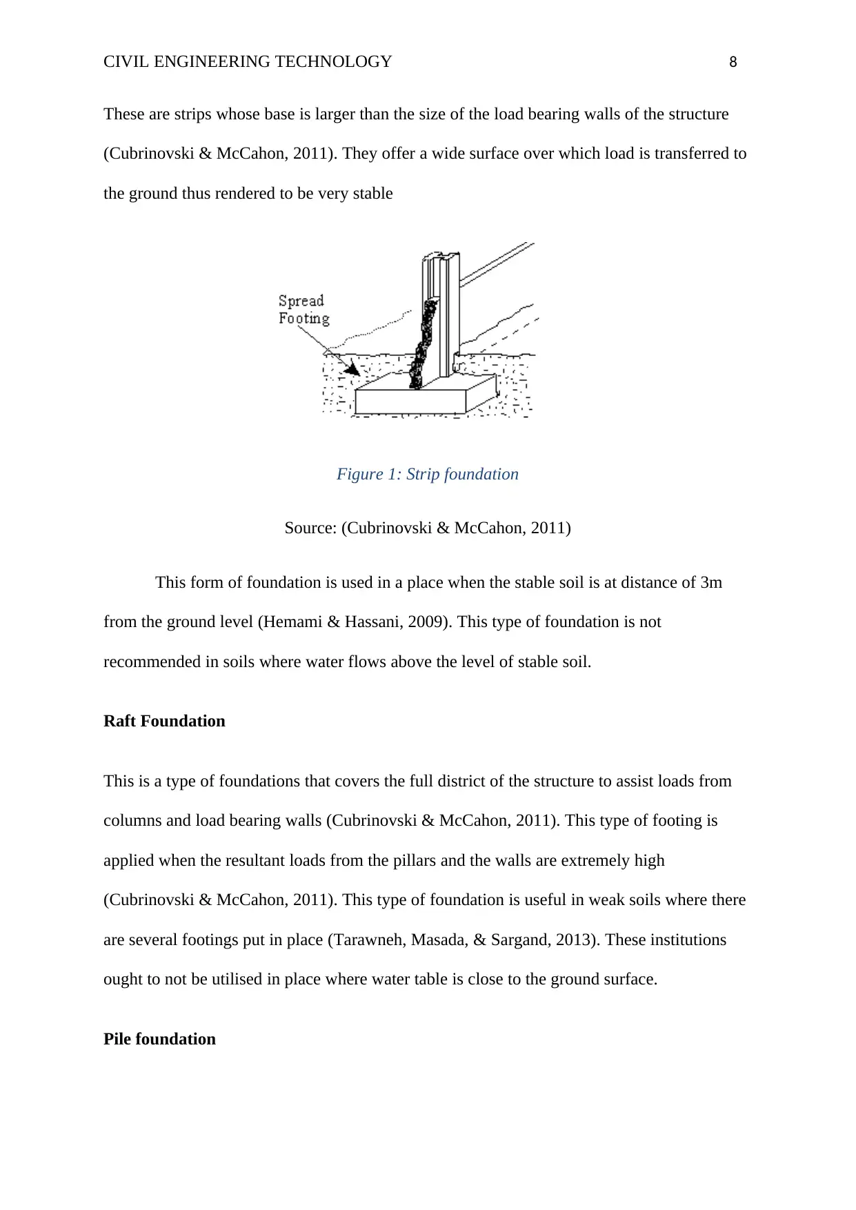
These are strips whose base is larger than the size of the load bearing walls of the structure
(Cubrinovski & McCahon, 2011). They offer a wide surface over which load is transferred to
the ground thus rendered to be very stable
Figure 1: Strip foundation
Source: (Cubrinovski & McCahon, 2011)
This form of foundation is used in a place when the stable soil is at distance of 3m
from the ground level (Hemami & Hassani, 2009). This type of foundation is not
recommended in soils where water flows above the level of stable soil.
Raft Foundation
This is a type of foundations that covers the full district of the structure to assist loads from
columns and load bearing walls (Cubrinovski & McCahon, 2011). This type of footing is
applied when the resultant loads from the pillars and the walls are extremely high
(Cubrinovski & McCahon, 2011). This type of foundation is useful in weak soils where there
are several footings put in place (Tarawneh, Masada, & Sargand, 2013). These institutions
ought to not be utilised in place where water table is close to the ground surface.
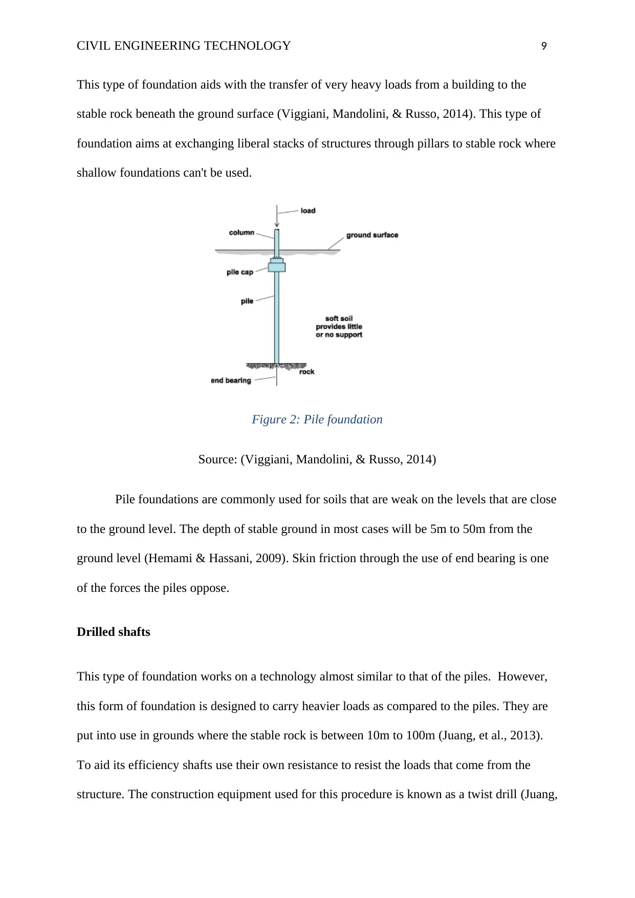
Pile foundation
CIVIL ENGINEERING TECHNOLOGY 9
This type of foundation aids with the transfer of very heavy loads from a building to the
stable rock beneath the ground surface (Viggiani, Mandolini, & Russo, 2014). This type of
foundation aims at exchanging liberal stacks of structures through pillars to stable rock where
shallow foundations can't be used.
Figure 2: Pile foundation
Source: (Viggiani, Mandolini, & Russo, 2014)
Pile foundations are commonly used for soils that are weak on the levels that are close
to the ground level. The depth of stable ground in most cases will be 5m to 50m from the
ground level (Hemami & Hassani, 2009). Skin friction through the use of end bearing is one
of the forces the piles oppose.
Drilled shafts
This type of foundation works on a technology almost similar to that of the piles. However,
this form of foundation is designed to carry heavier loads as compared to the piles. They are
put into use in grounds where the stable rock is between 10m to 100m (Juang, et al., 2013).
To aid its efficiency shafts use their own resistance to resist the loads that come from the
structure. The construction equipment used for this procedure is known as a twist drill (Juang,
⊘ This is a preview!⊘
Do you want full access?
Subscribe today to unlock all pages.

Trusted by 1+ million students worldwide
CIVIL ENGINEERING TECHNOLOGY 10
et al., 2013). This procedure is however not appropriate in instances where there are deposits
of wet soil at the point where the hard stable rock is.
Present a safety plan risk assessment and method statement for a given civil engineering
activity.
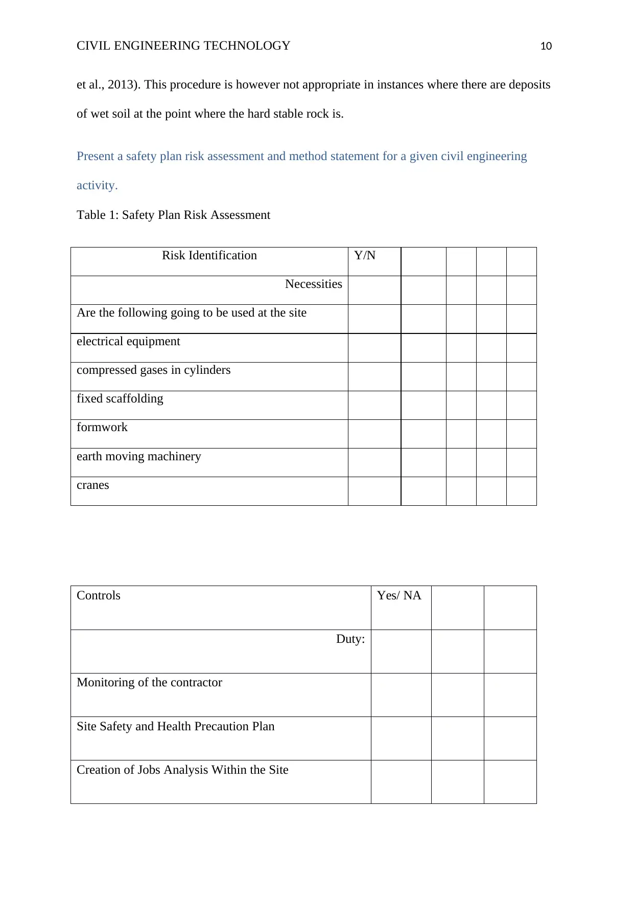
Table 1: Safety Plan Risk Assessment
Risk Identification Y/N
Necessities
Are the following going to be used at the site
electrical equipment
compressed gases in cylinders
fixed scaffolding
formwork
earth moving machinery
cranes
Controls Yes/ NA
Duty:
Monitoring of the contractor
Site Safety and Health Precaution Plan
Creation of Jobs Analysis Within the Site
Paraphrase This Document
Need a fresh take? Get an instant paraphrase of this document with our AI Paraphraser
CIVIL ENGINEERING TECHNOLOGY 11
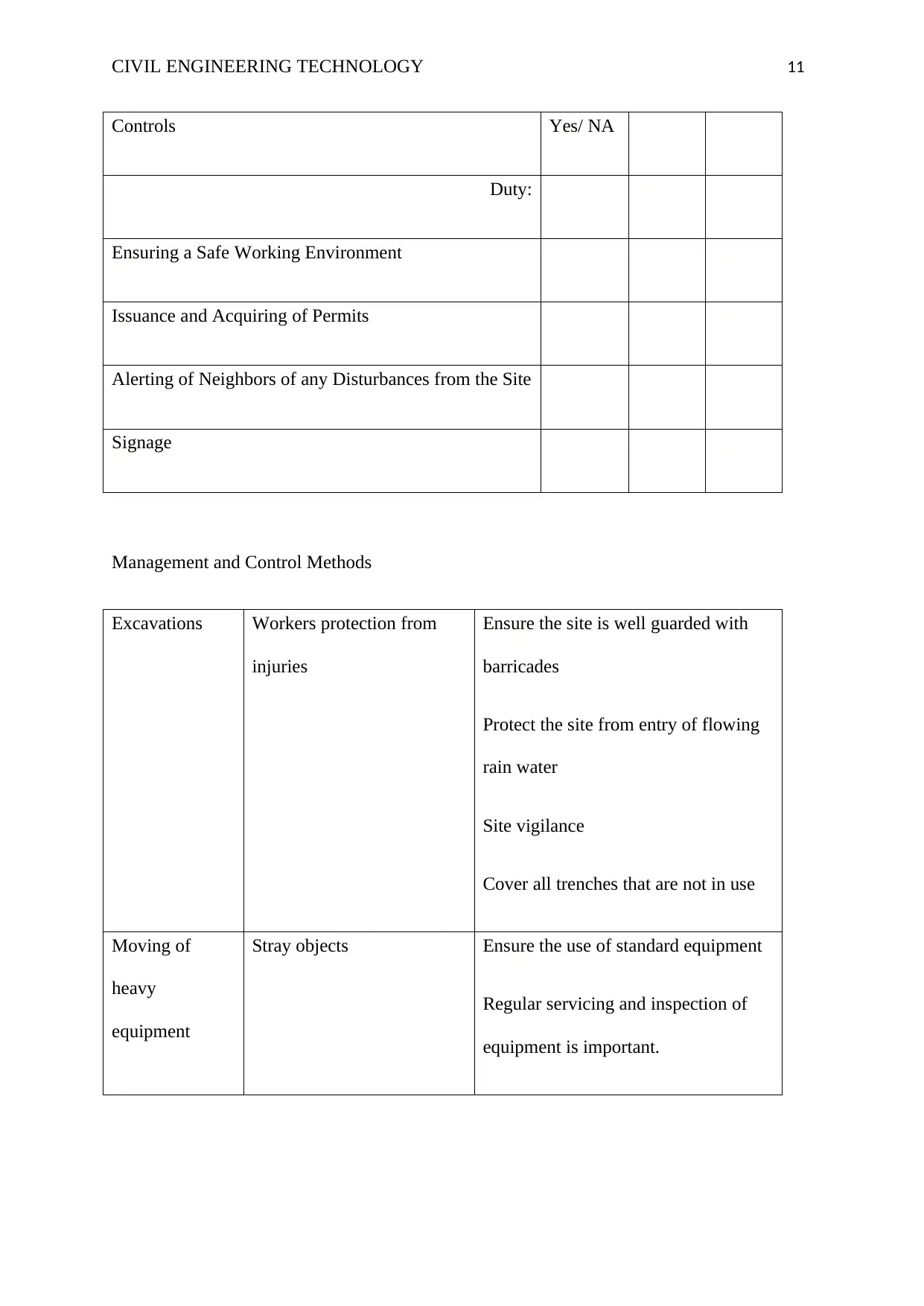
Controls Yes/ NA
Duty:
Ensuring a Safe Working Environment
Issuance and Acquiring of Permits
Alerting of Neighbors of any Disturbances from the Site
Signage
Management and Control Methods
Excavations Workers protection from
injuries
Ensure the site is well guarded with
barricades
Protect the site from entry of flowing
rain water
Site vigilance
Cover all trenches that are not in use
Moving of
heavy
equipment
Stray objects Ensure the use of standard equipment
Regular servicing and inspection of
equipment is important.
CIVIL ENGINEERING TECHNOLOGY 12
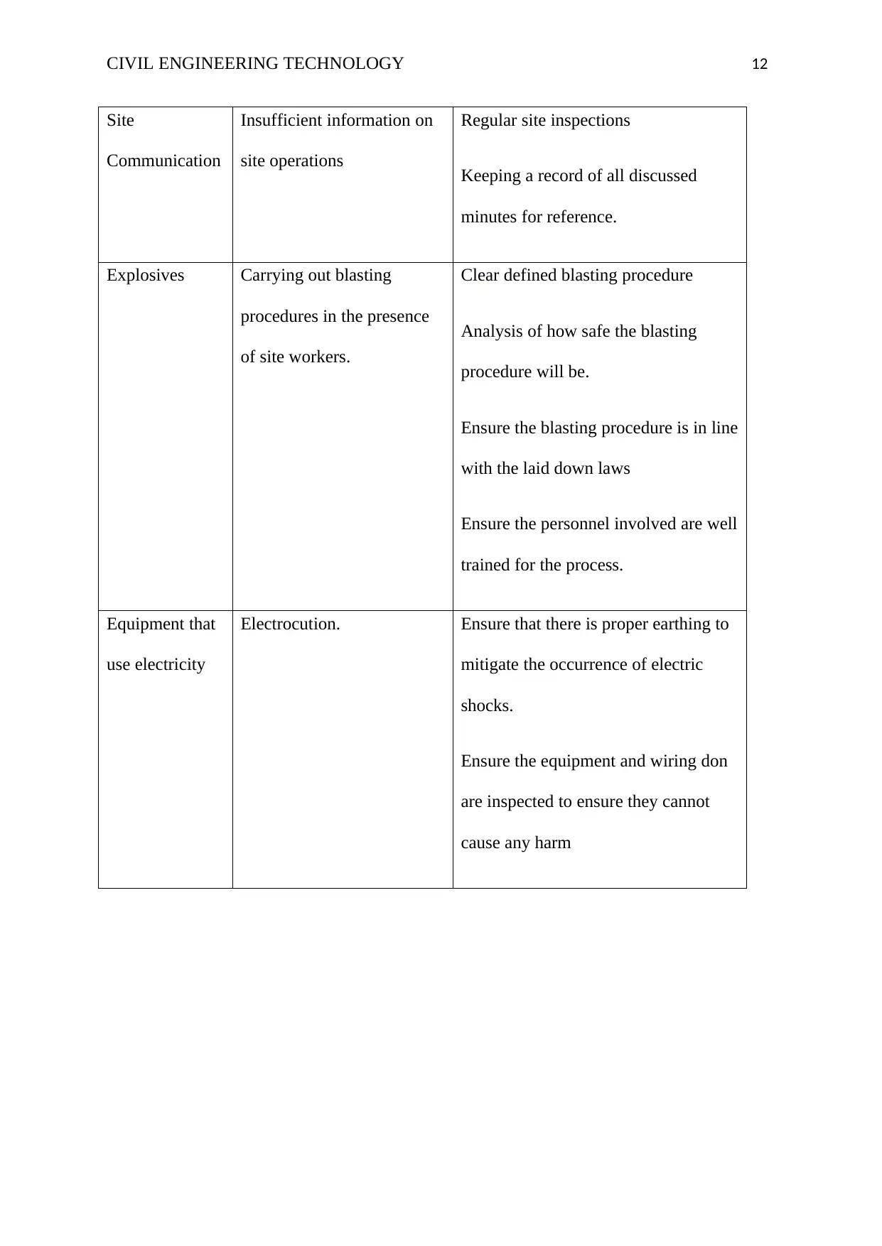
Site
Communication
Insufficient information on
site operations
Regular site inspections
Keeping a record of all discussed
minutes for reference.
Explosives Carrying out blasting
procedures in the presence
of site workers.
Clear defined blasting procedure
Analysis of how safe the blasting
procedure will be.
Ensure the blasting procedure is in line
with the laid down laws
Ensure the personnel involved are well
trained for the process.
Equipment that
use electricity
Electrocution. Ensure that there is proper earthing to
mitigate the occurrence of electric
shocks.
Ensure the equipment and wiring don
are inspected to ensure they cannot
cause any harm
⊘ This is a preview!⊘
Do you want full access?
Subscribe today to unlock all pages.

Trusted by 1+ million students worldwide
1 out of 17
Related Documents
Your All-in-One AI-Powered Toolkit for Academic Success.
+13062052269
info@desklib.com
Available 24*7 on WhatsApp / Email
![[object Object]](/_next/static/media/star-bottom.7253800d.svg)
Unlock your academic potential
Copyright © 2020–2025 A2Z Services. All Rights Reserved. Developed and managed by ZUCOL.


