logo

Systematic Identification of Consistency


Added on  2022-08-21

8 Pages991 Words17 Views
 | 
 | 
 | 
Running head: COFEEMAKERFACTORY PROCESS PATTERN CREATION
CofeeMakerFactory Process Pattern Creation
Name of the Student
Name of the University
Author Note
Systematic Identification of Consistency_1

COFEEMAKERFACTORY PROCESS PATTERN CREATION1
Table of Contents
Introduction................................................................................................................................2
Discussion..................................................................................................................................2
Diagram..................................................................................................................................3
Conclusion..................................................................................................................................6
Reference....................................................................................................................................7
Systematic Identification of Consistency_2

COFEEMAKERFACTORY PROCESS PATTERN CREATION2
Introduction
A UML diagram is used to represent a system structure along with its interactions
with various actors or classes. The diagram generated using UML can be both structural and
functional. In the following parts of this paper, a case study of the coffee maker factory
process will be used and you will get a detailed idea about the UML diagram (Torre et al.,
2018). In addition you will also get accustomed about how to implement an UML diagram
into corresponding Object Oriented Code (C++ will be discussed here).
Discussion
The UML diagram will be used to explain the Forward design of the Use case ‘Coffee
Maker Factory Process.’ The functional part of the use case will be discussed along with the
coding of the same in the C++ Object Oriented form. The coding part will solely be based on
the concept of objects (Fernández-Sáez et al., 2015). As for the use case ‘Coffee Maker
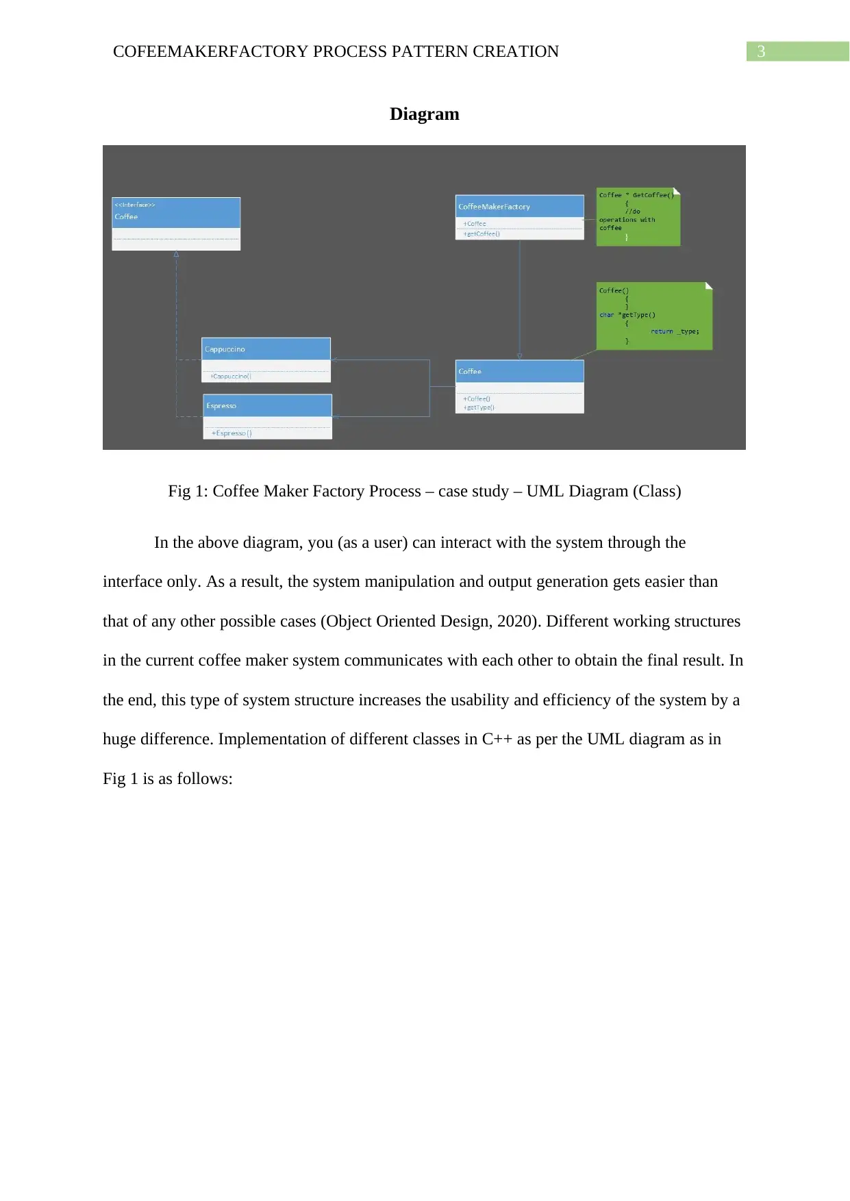
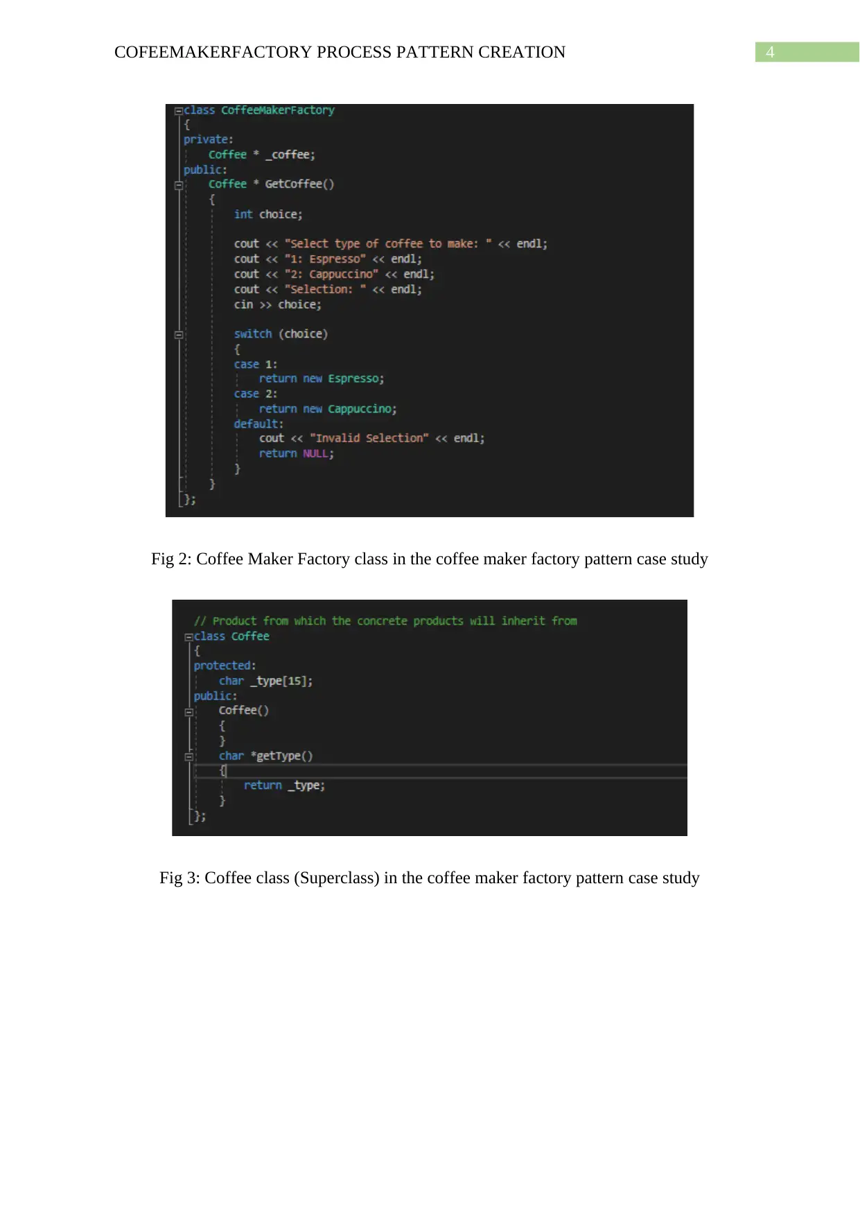
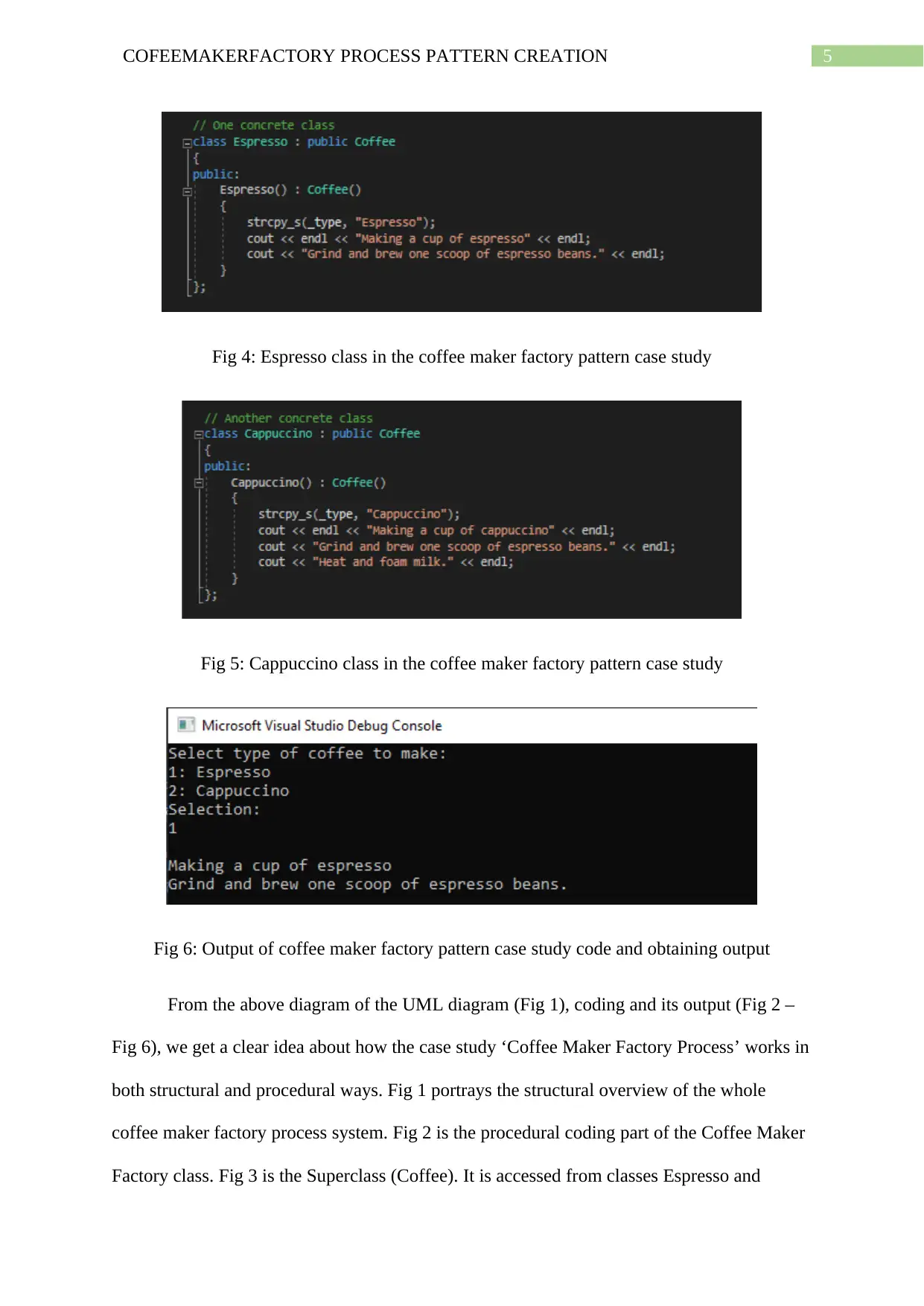
Factory’, there will be an interface system where the user will wet a prompt to select the type
of coffee that s/he wants. Upon entering the choice, s/he will receive his /her selected coffee.
The whole task will be done on an object-based return type coding using c++ programming
language.
There are many UML drawing tools that can be used to draw any required system
UML diagram. The tools varies from Lucidchart to AgroUML, Magic Draw, Microsoft Visio,
and many more (Agner, Lethbridge & Soares, 2019). For the ease of drawing and
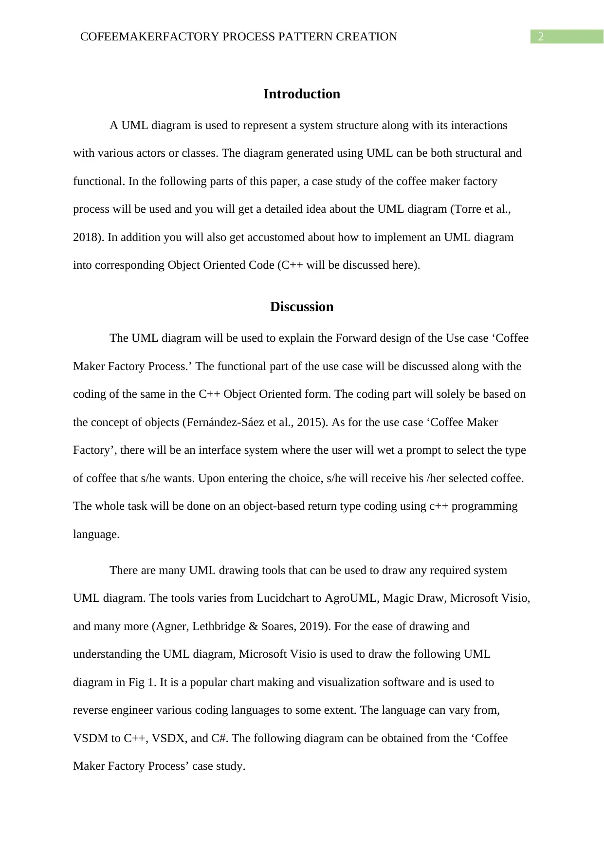
understanding the UML diagram, Microsoft Visio is used to draw the following UML
diagram in Fig 1. It is a popular chart making and visualization software and is used to
reverse engineer various coding languages to some extent. The language can vary from,
VSDM to C++, VSDX, and C#. The following diagram can be obtained from the ‘Coffee
Maker Factory Process’ case study.
Systematic Identification of Consistency_3

End of preview

Want to access all the pages? Upload your documents or become a member.

Related Documents
Car Factory Pattern Creation
|8
|1233
|13

System Design Analysis Using UML PDF
|5
|950
|81

A hands on introduction for developers : Design and UML Class Diagrams
|31
|1710
|165

Create Objects With Creational Design Patterns
|7
|823
|17

Animal Cloning Using Prototype Design Pattern
|10
|2180
|9

Software Development Productivity Enhancement through Creational Design Patterns
|8
|1465
|270