Detailed Analysis of Steel Portal Frames in Commercial Construction
VerifiedAdded on 2023/06/05
|14
|3089
|64
Report
AI Summary
This research report provides a detailed analysis of steel portal frames in commercial construction, focusing on structural layout, construction sequences, and lateral stability. It examines the design and implementation of steel portal frames, including haunch connections, column supports, and separation walls between tenancies. The report includes annotated line diagrams illustrating the construction sequence for typical steel portal frames and discusses components assembled on the ground prior to erection. It also addresses the integration of block work dividers for stability, the analysis of end frames, and the importance of rafter connections with bolts and nuts. Furthermore, the report investigates how wind loads are transferred to wind trusses, emphasizing the role of shear walls and diaphragms in ensuring structural integrity. The study references various sources and standards to support its findings, offering insights into the design considerations and practical applications of steel portal frames in commercial buildings. Desklib is a platform where students can find similar solved assignments and study resources.

Research Project: Commercial Construction 1
Research Project: Commercial Construction
by Student’s Name
Code + Course Name
Professor’s Name
University Name
City, State
Date
Research Project: Commercial Construction
by Student’s Name
Code + Course Name
Professor’s Name
University Name
City, State
Date
Paraphrase This Document
Need a fresh take? Get an instant paraphrase of this document with our AI Paraphraser
Research Project: Commercial Construction 2
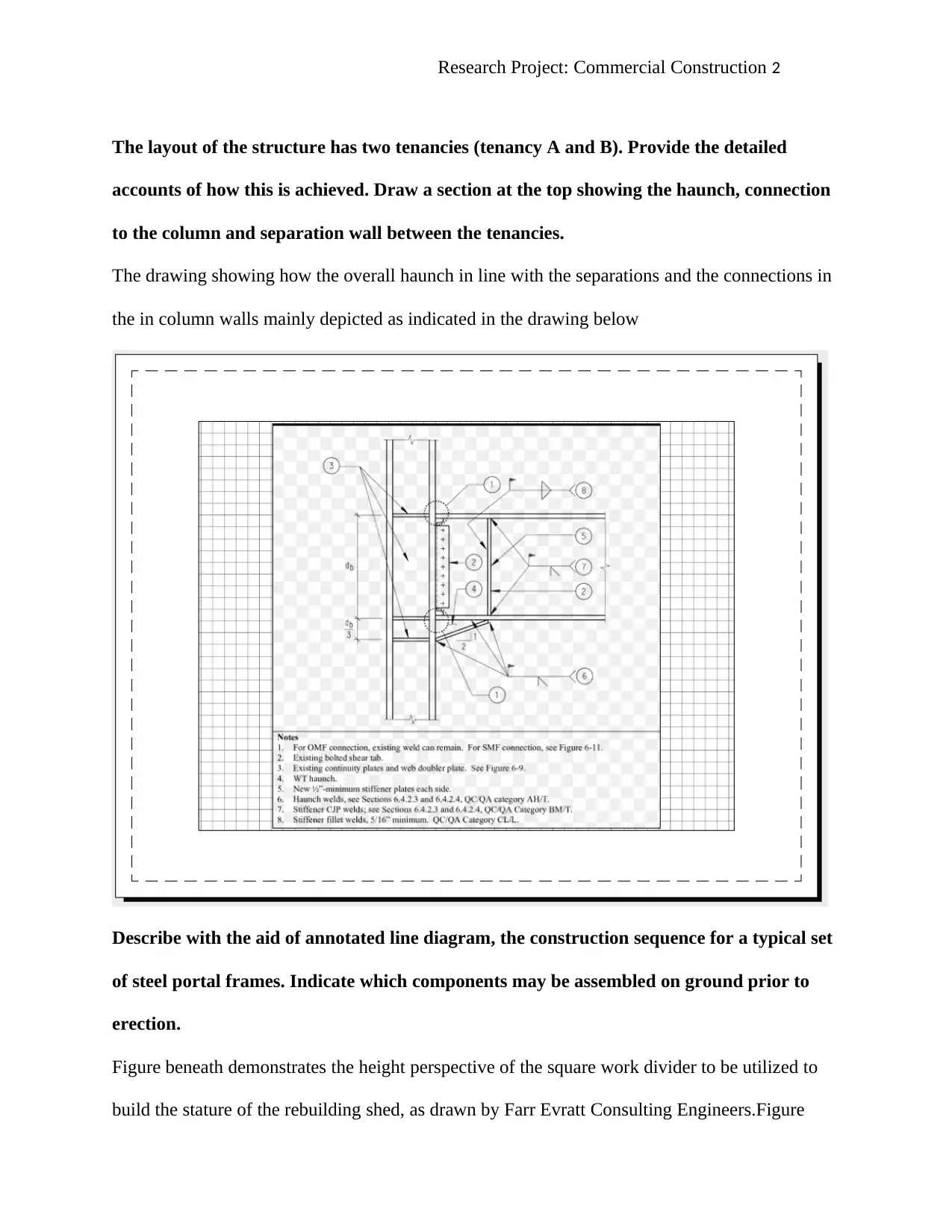
The layout of the structure has two tenancies (tenancy A and B). Provide the detailed
accounts of how this is achieved. Draw a section at the top showing the haunch, connection
to the column and separation wall between the tenancies.
The drawing showing how the overall haunch in line with the separations and the connections in
the in column walls mainly depicted as indicated in the drawing below
Describe with the aid of annotated line diagram, the construction sequence for a typical set
of steel portal frames. Indicate which components may be assembled on ground prior to
erection.
Figure beneath demonstrates the height perspective of the square work divider to be utilized to
build the stature of the rebuilding shed, as drawn by Farr Evratt Consulting Engineers.Figure

Research Project: Commercial Construction 3
from the Besser item index depicts what size and sort of fortifying are fitting to use inside the
square work divider. All support measured from the Besser index has already been checked to be
inside the Australian Standards limits. The block work divider has been incorporated between the
solid wharfs to balance out them and oppose any level development of docks as they take the
heap from the segments. Since the block work divider holding any dirt or fill as point by point in
the Besser Product inventory and, there is no compelling reason to include a key as appeared at
the base of the square divider. The chunk will be thickened around the edge of shed design to
give additional help to the fundamental auxiliary loadings. The analysis for the overall process
mainly indicated as shown in the diagram analysis below (Raj, Sundar and Sannasiraj 2019
p.146).
⊘ This is a preview!⊘
Do you want full access?
Subscribe today to unlock all pages.

Trusted by 1+ million students worldwide
Research Project: Commercial Construction 4
The end frame of the building is not a portal frame.
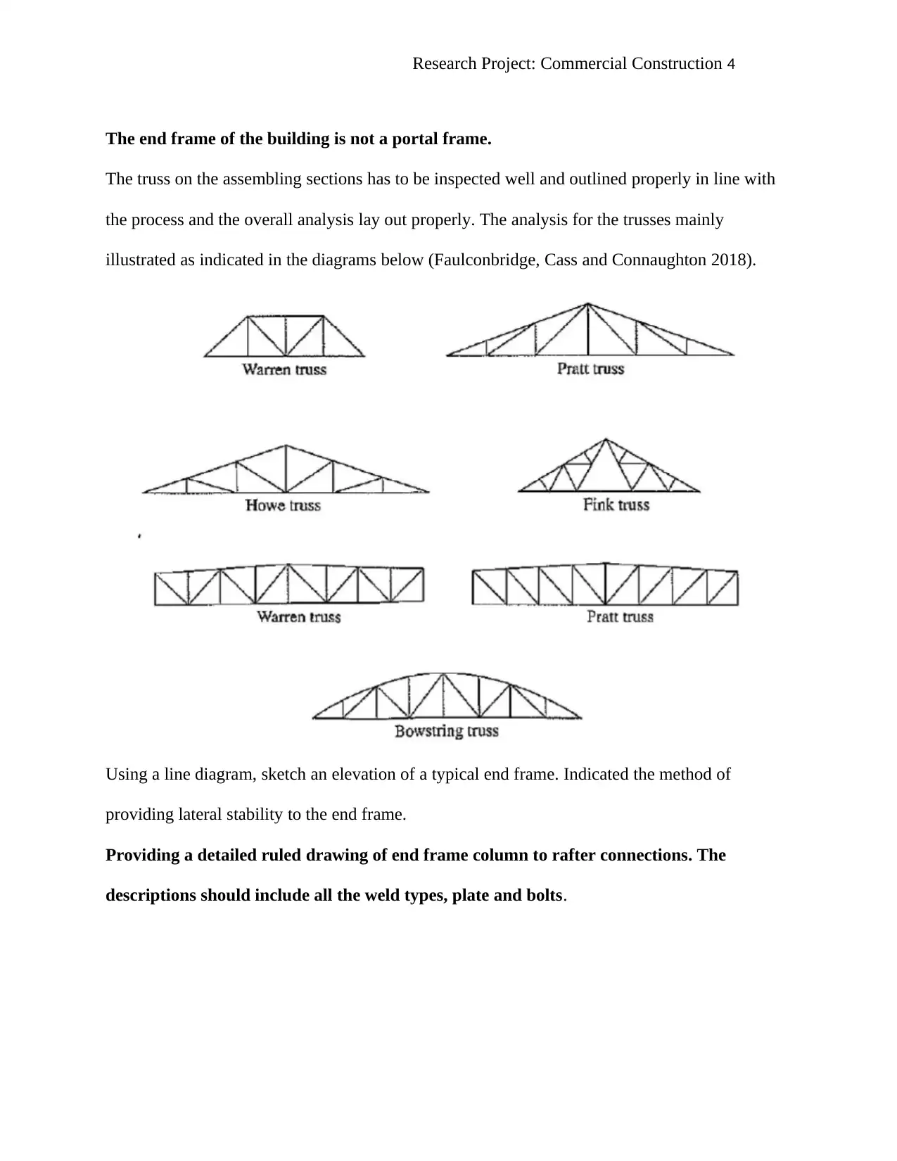
The truss on the assembling sections has to be inspected well and outlined properly in line with
the process and the overall analysis lay out properly. The analysis for the trusses mainly
illustrated as indicated in the diagrams below (Faulconbridge, Cass and Connaughton 2018).
Using a line diagram, sketch an elevation of a typical end frame. Indicated the method of
providing lateral stability to the end frame.
Providing a detailed ruled drawing of end frame column to rafter connections. The
descriptions should include all the weld types, plate and bolts.
Paraphrase This Document
Need a fresh take? Get an instant paraphrase of this document with our AI Paraphraser
Research Project: Commercial Construction 5
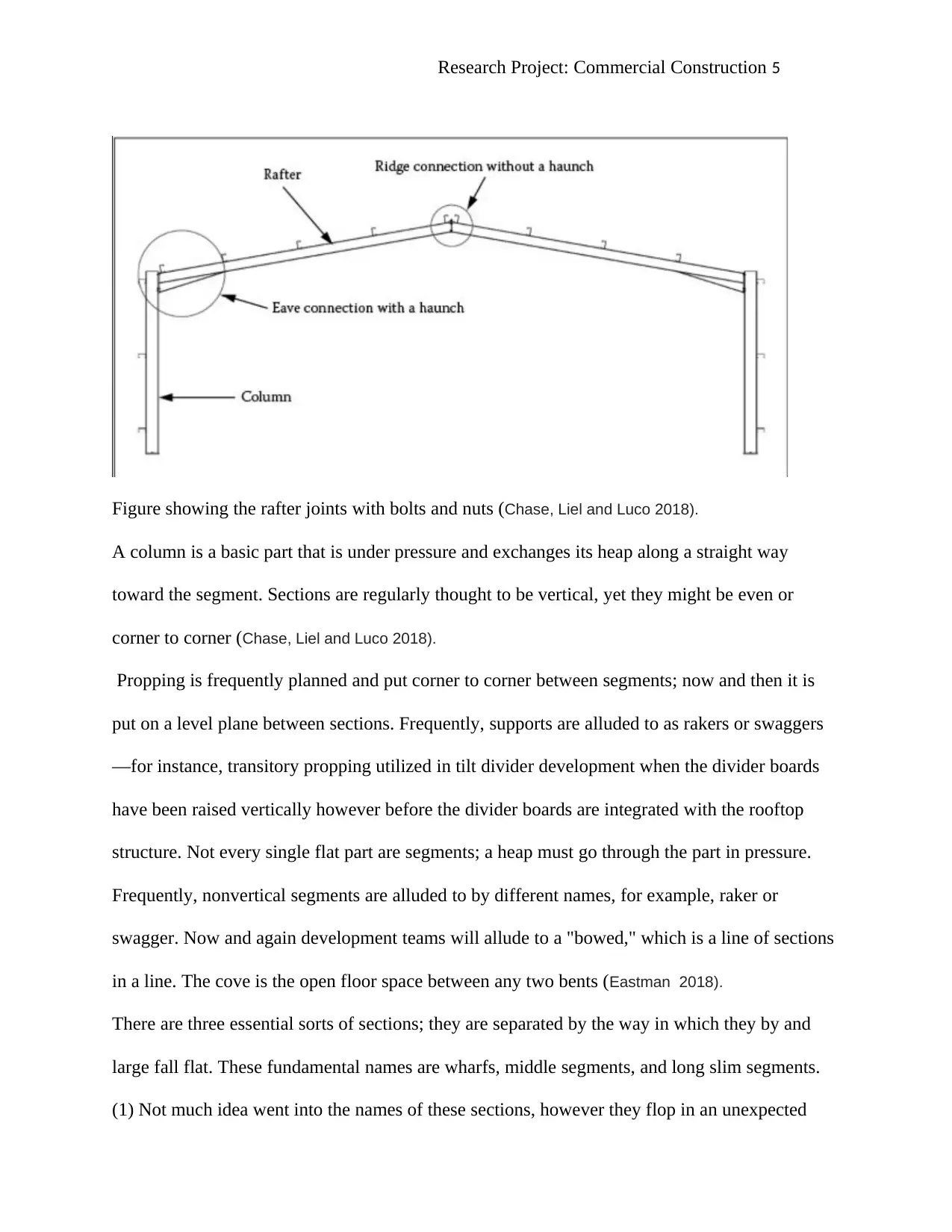
Figure showing the rafter joints with bolts and nuts (Chase, Liel and Luco 2018).
A column is a basic part that is under pressure and exchanges its heap along a straight way
toward the segment. Sections are regularly thought to be vertical, yet they might be even or
corner to corner (Chase, Liel and Luco 2018).
Propping is frequently planned and put corner to corner between segments; now and then it is
put on a level plane between sections. Frequently, supports are alluded to as rakers or swaggers
—for instance, transitory propping utilized in tilt divider development when the divider boards
have been raised vertically however before the divider boards are integrated with the rooftop
structure. Not every single flat part are segments; a heap must go through the part in pressure.
Frequently, nonvertical segments are alluded to by different names, for example, raker or
swagger. Now and again development teams will allude to a "bowed," which is a line of sections
in a line. The cove is the open floor space between any two bents (Eastman 2018).
There are three essential sorts of sections; they are separated by the way in which they by and
large fall flat. These fundamental names are wharfs, middle segments, and long slim segments.
(1) Not much idea went into the names of these sections, however they flop in an unexpected
Research Project: Commercial Construction 6
way. The long slim section flops by bowing or contorting, alluded to as "clasping." The dock, or
squat segment, bombs by squashing. The halfway section may bomb in either way.
The length of the segment decides its heap conveying limit. The shorter a section, the more it can
convey. The heap conveying limit of a segment diminishes as the length is expanded. A segment
will lose quality by the square of the adjustment long. A 16-foot-high section will convey one-
fourth the heap of an eight-foot-high segment. Once a segment begins to bomb, there is almost
no hold quality to oppose the fall—as such, once a section begins to come up short, you are
presumably not going to stop it. Supporting safely put at the midpoint of a segment will
successfully build the segment's heap conveying capacity, making two sections of equivalent
length and quality. Indeed, even with this propping, a section will bomb quickly when it achieves
the basic yield stack.
A segment is round and hollow and empty, enabling the heap to be set as far from the focal point
of the chamber as would be prudent. Working with round barrels is troublesome. Appending bars
to round sections can prompt outline issues with feel in the last wrapping up. Mainstream
segment shapes are round, box, and presumably the most prevalent "H." These shapes will loan
themselves well to the barrel shaped section hypothesis. The "H" and box outlines will enable a
hover to be drawn including the best and base of every leg of the "H," or the four corners of the
container, while looking down on the finish of the section. It is less demanding to append braces,
pillars, dividers, and other building segments to the container and "H" shapes than it is to round
building segments (Hsieh and Chien 2018).
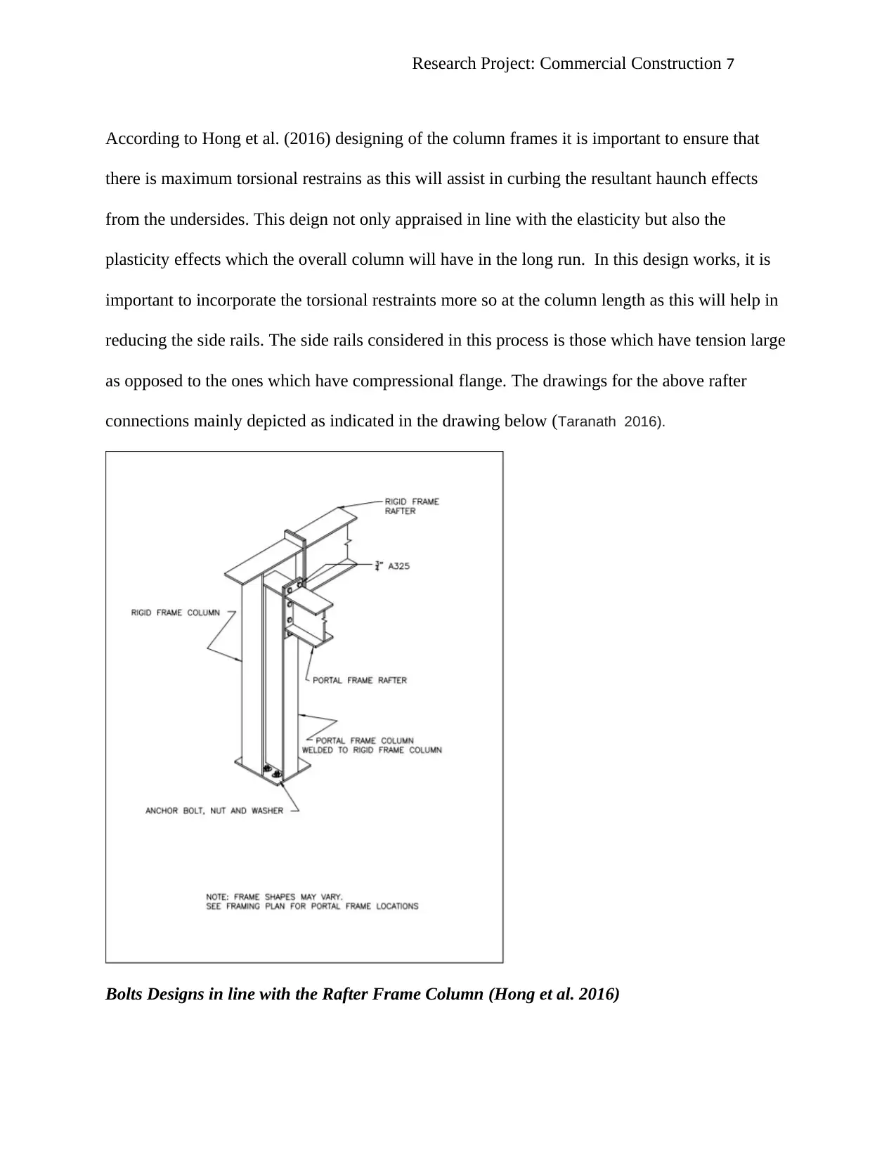
Rafter Connections Frame Column
⊘ This is a preview!⊘
Do you want full access?
Subscribe today to unlock all pages.

Trusted by 1+ million students worldwide
Research Project: Commercial Construction 7
According to Hong et al. (2016) designing of the column frames it is important to ensure that
there is maximum torsional restrains as this will assist in curbing the resultant haunch effects
from the undersides. This deign not only appraised in line with the elasticity but also the
plasticity effects which the overall column will have in the long run. In this design works, it is
important to incorporate the torsional restraints more so at the column length as this will help in
reducing the side rails. The side rails considered in this process is those which have tension large
as opposed to the ones which have compressional flange. The drawings for the above rafter
connections mainly depicted as indicated in the drawing below (Taranath 2016).
Bolts Designs in line with the Rafter Frame Column (Hong et al. 2016)
Paraphrase This Document
Need a fresh take? Get an instant paraphrase of this document with our AI Paraphraser
Research Project: Commercial Construction 8
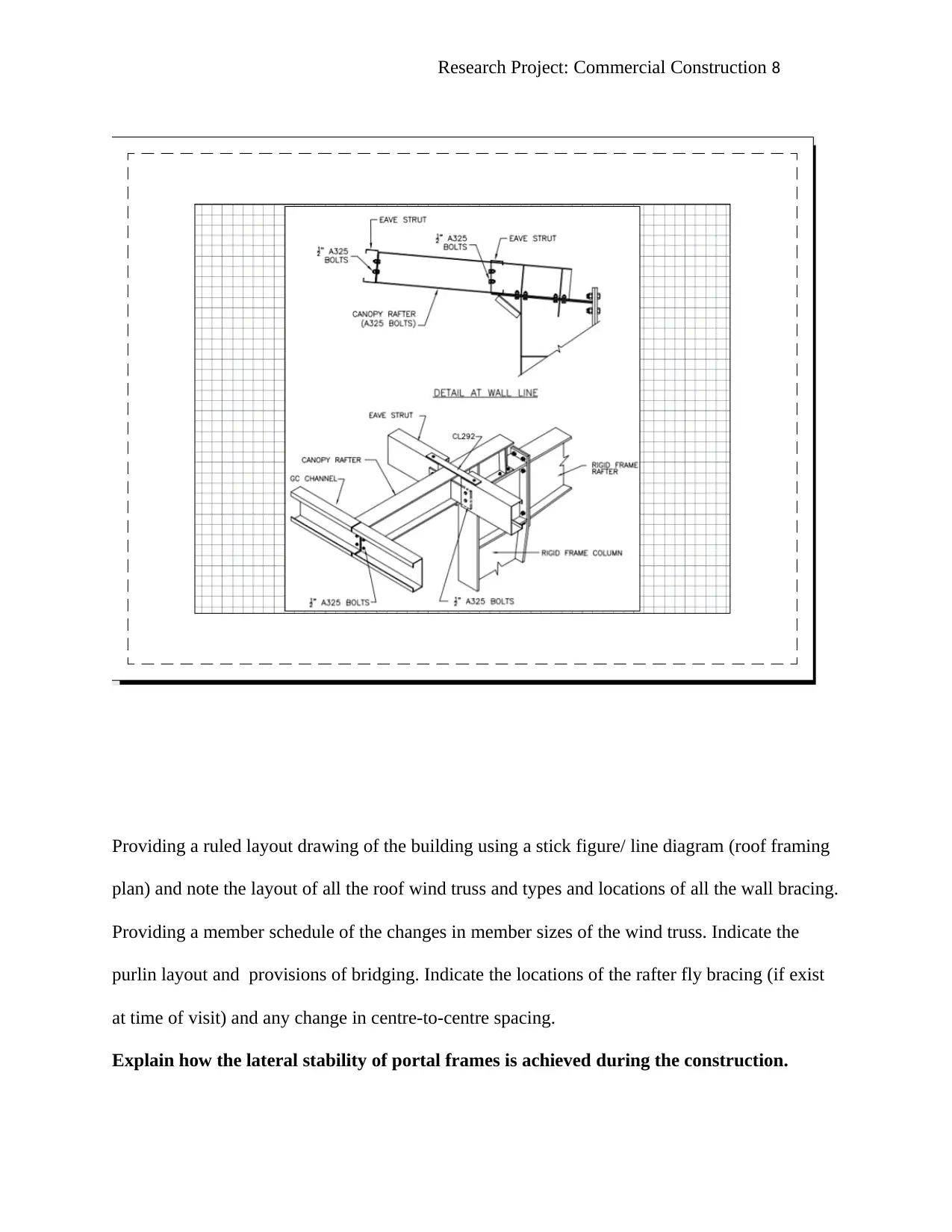
Providing a ruled layout drawing of the building using a stick figure/ line diagram (roof framing
plan) and note the layout of all the roof wind truss and types and locations of all the wall bracing.
Providing a member schedule of the changes in member sizes of the wind truss. Indicate the
purlin layout and provisions of bridging. Indicate the locations of the rafter fly bracing (if exist
at time of visit) and any change in centre-to-centre spacing.
Explain how the lateral stability of portal frames is achieved during the construction.
Research Project: Commercial Construction 9
First and foremost, the portal frames mainly described as low-rise structures and they tend to
consist of both the pitched rafters which are horizontal in shape as well as columns. Furthermore,
there is the moment-resisting connection which exists between the overall connected chains in
the system. During the construction, the resistance manifested in line with the vertical and lateral
actions mainly curbed via the application of rigidity connections as well as members bending
stiffness (Raj, Sundar and Sannasiraj 2019 p.143).
Additionally, haunch mainly used in the process to increase the overall lateral as well as the
vertical actions by deepening the overall rafter sections. Moreover, the continuous frame
structures used in the process mainly helps in attaining the required stability and thus, provides a
clear span as well as plane that is not obstructed with the bracing effects. The commonly
application of the portal frames is in the United Kingdom. In this region, at least 50% of the total
frames used in the construction sector mainly results from the portal frames. The applications of
the portal constructions mainly tend across the board. These applications include industrial,
storage, agricultural purposes, retail as well as commercial applications (Kováts, Thévenin and
Zähringer 2018).
Describe how the how wind loads are transferred to the wind trusses located at the end
bay.
The choose made when design for the diaphragms and the overall walls in line with the shear
forces resulting from the wind loads is not only essential but equally important in the process.
Thus, it is important for the engineer to design the critical wind resistant and loads via the
application of the building codes and the utilization of the structural components (Acha et al.
2018).
⊘ This is a preview!⊘
Do you want full access?
Subscribe today to unlock all pages.

Trusted by 1+ million students worldwide
Research Project: Commercial Construction 10
The essential aspect in this process mainly entails the utilization of the various aspects in
ensuring that the main wind loads as well as the resultant forces in line with the system mainly
incorporated in the process. Some of the key components mainly incorporated in the process
include the shear walls as well as the diaphragms (Chase, Liel and Luco 2018). In essence, wood
structure as well as panels mainly considered in the installation of the sheathing over the
makeable floors and the roofs. This is important since they help in ensuring that the proper
support for the structure is achieved in line with the diaphragm. Also, the design include the
utilization of the flat structural and unit, girder and thin I-beam which aims at curbing any
resultant forces developed out of the lateral resistance (Wijerathna and Liyanapathirana 2018).
The diaphragm mainly role in the design is to act as the demarcated beam web resist shear. On
the other hand, the edge members utilized in the process mainly functions as the parametric
resisting and flanges to the overall bending stresses in the system. Additionally, it is important to
note that the edge members used in the construction of the structure mainly termed as the
parametric chords in line with the diaphragms. In essence, the diaphragm design incorporates
the application of the ledgers, joists, top plates, trusses as well as the related wood components
(Day 2017).
Furthermore, the examination of the diaphragms used in the building process established that the
systems mainly various basing on their carrying capacity. The classifications of these systems
mainly grouped into two mainly sub classes that is the blocked and the unblocked. Conversely,
the wood structures may be used in the process (Acha et al., 2018 p.579). The categories of the
woods used in the constructions of the roofing in line with the wind loads and the pressure they
exert on the wall s include structural fiberboard, wood panels, board sheathing as well as the
Paraphrase This Document
Need a fresh take? Get an instant paraphrase of this document with our AI Paraphraser
Research Project: Commercial Construction 11
frame fastening. All the process involved in the mechanism aims at ensuring that the shear
balanced mainly attained at the walling and on the overall structure (Mangalore 2018 p.120).
Notably, the shear walls tend to receive the overall reactions from the makeable floor diagrams
and the roofs. These forces and the reactions are then transmitted to the foundation.
Moreover, the critical role of the shear walls in the design is to ensure that they resist any
reactions coming from the lateral forces and resistance resulting from the plane walls. Thus,
shear walls in the design mainly functions as the cantilever diaphragm. Hence, the load primarily
applied at the wall top and thereafter transferred to the wall foundation bottom (Moss and
Marvin 2016).
Moreover, there are resultant pressures mainly associated with actions of the winds in the area.
Some of the effects extend to the walls of the structures. The pressure exerted as a result of the
wind actions not only affects the operations of the inward sections but also manifested at the
outward ends of the structure. Thus, this operation tends to affect the operations of the exterior
surface of the building structure as a whole (Mangalore 2018).
Thus, there are a number of design considerations mainly put in place in ensuring the normalcies
resulting from the effects and impacts often tackled imminently. The considerations primarily
range from the vertical floor to the overall roof design pressures. The mainly pressures described
too often results from the gravity loading in the area. In situations in which the building structure
has the inability to curb, and accommodate the wind loads exerted on it, then it is important that
sheathing be incorporated as the alternative approach. According Lendvai and Joó (2018) the
section 1609.3 of the parametric 2003 IBC laws, it is stipulated clearly that the system,
components as well as the structure as a whole must be in decisive manner to curb the resist
winds often induced on it. This includes the overturning, sliding as well as uplift effects.
Research Project: Commercial Construction 12
Therefore, in ensuring that there a decisive and well-structure plan for curbing the loads
resulting from the wind, then it is important to incorporate the continuous load paths as well as
the forces which they have in the foundation system. This is important in ensuring that the wind
forces in the system does not exceed the overall foundation s well as the system and thus,
minimizes the chances of occurrence of the overturning and the sliding effects (Vrettos et al.
2018).
⊘ This is a preview!⊘
Do you want full access?
Subscribe today to unlock all pages.

Trusted by 1+ million students worldwide
1 out of 14
Your All-in-One AI-Powered Toolkit for Academic Success.
+13062052269
info@desklib.com
Available 24*7 on WhatsApp / Email
![[object Object]](/_next/static/media/star-bottom.7253800d.svg)
Unlock your academic potential
Copyright © 2020–2026 A2Z Services. All Rights Reserved. Developed and managed by ZUCOL.