University Communication Systems Homework Assignment Solutions
VerifiedAdded on 2020/04/15

Communication Systems
Paraphrase This Document
Problem-1.............................................................................................................................................2
(a) Free space path loss.............................................................................................................2
(b) Local oscillator.....................................................................................................................3
Determine the frequency ratio....................................................................................................3
Determine the image frequency..................................................................................................4
(c) Auto correlation function....................................................................................................4
Problem-2.............................................................................................................................................4
(a) Frequency re-use in cellular system.......................................................................................4
(b) Duplexer in cellular system.....................................................................................................6
(c) Multiple access technique........................................................................................................6
Problem-3.............................................................................................................................................9
(a) Find the power spectral density of the output Sy(f)..............................................................9
(b) Auto correlation of the output signal R(y)τ.........................................................................10
(c) Output signal p y....................................................................................................................10
Problem -4..........................................................................................................................................10
(a) Determine the overall noise figure of the cascade......................................................................10
(b) Input power..................................................................................................................................11
(c ) Suppose amplifier 1 and 2 are interchanged. the noise figure cascade is F1 =6,F2=0............11
Problem- 5..........................................................................................................................................11
(a)Overall nosie factor......................................................................................................................11
(b)The overall noise figure if a preamplifier....................................................................................12
( c) The overall noise figure if the amplifier.....................................................................................12
Problem -6..........................................................................................................................................12
(a) Auto correlation function......................................................................................................12
(b) Power spectral density...........................................................................................................12
Problem – 7........................................................................................................................................12
(a) Briefly explain the role of the blocks labelled RF amplifier and Limiter in the diagram.......12
(b) Find the bandwidths required for the RF amplifier, IF amplifier, and of the audio
amplifier.............................................................................................................................................15
(c) Larger bandwidth..................................................................................................................16
Problem- 8..........................................................................................................................................16
(a) Briefly explain what is meant by an ergodic random process............................................16
(b) Determine whether or not the random process X (t) is an ergodic random process.........17
(c) Random process is uniformly distribution is X (t) an ergodic random process................18

⊘ This is a preview!⊘
Do you want full access?
Subscribe today to unlock all pages.

Trusted by 1+ million students worldwide
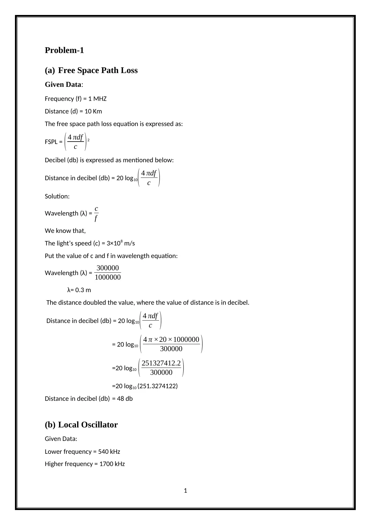
(a) Free Space Path Loss
Given Data:
Frequency (f) = 1 MHZ
Distance (d) = 10 Km
The free space path loss equation is expressed as:
FSPL = ( 4 πdf
c )2
Decibel (db) is expressed as mentioned below:
Distance in decibel (db) = 20 log10( 4 πdf
c )
Solution:
Wavelength (λ) = c
f
We know that,
The light’s speed (c) = 3×10⁸ m/s
Put the value of c and f in wavelength equation:
Wavelength (λ) = 300000
1000000
λ= 0.3 m
The distance doubled the value, where the value of distance is in decibel.
Distance in decibel (db) = 20 log10
( 4 πdf
c )
= 20 log10 ( 4 π ×20 ×1000000
300000 )
=20 log10 ( 251327412.2
300000 )
=20 log10 (251.3274122)
Distance in decibel (db) = 48 db
(b) Local Oscillator
Given Data:
Lower frequency = 540 kHz
Higher frequency = 1700 kHz
1
Paraphrase This Document
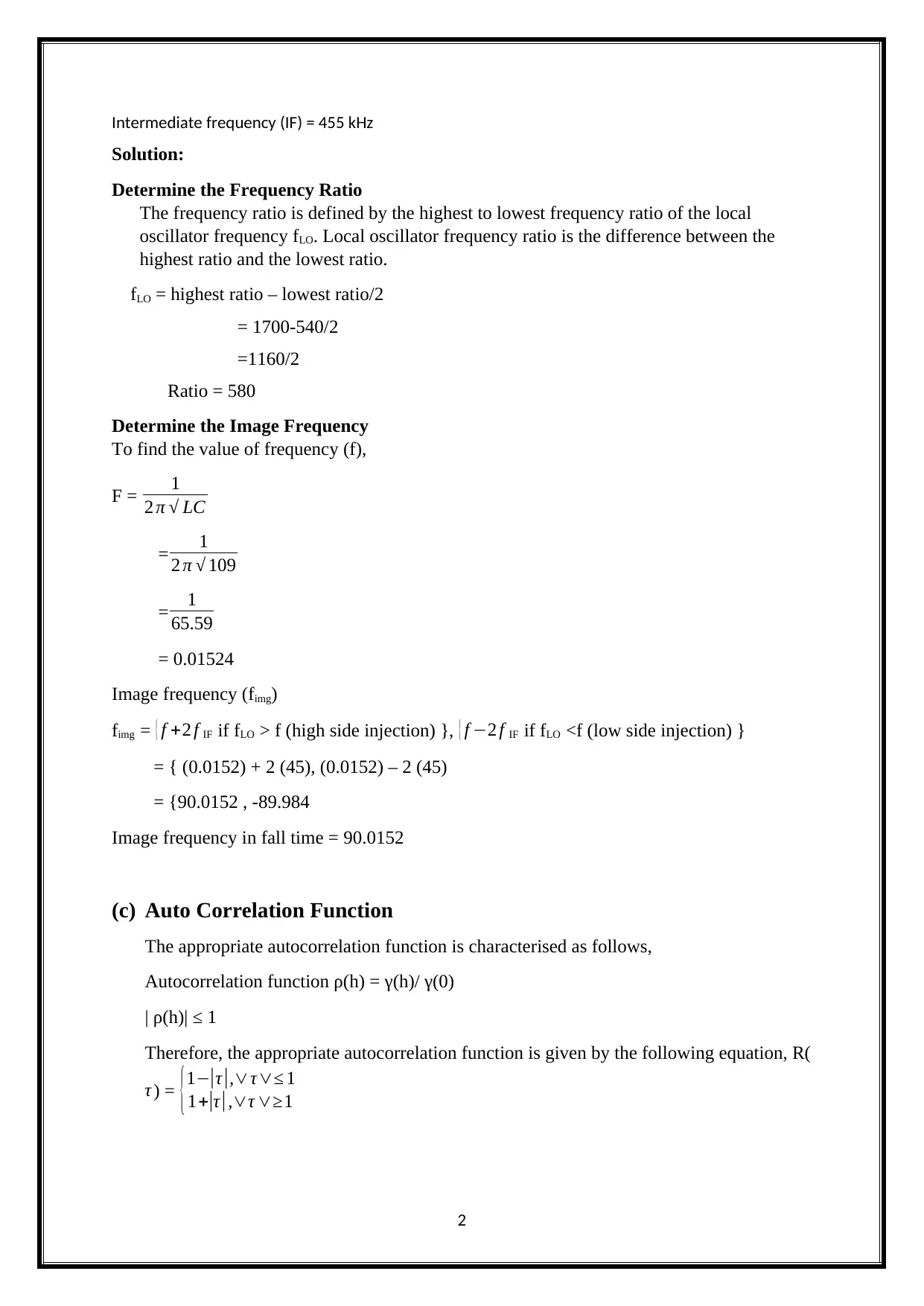
Solution:
Determine the Frequency Ratio
The frequency ratio is defined by the highest to lowest frequency ratio of the local
oscillator frequency fLO. Local oscillator frequency ratio is the difference between the
highest ratio and the lowest ratio.
fLO = highest ratio – lowest ratio/2
= 1700-540/2
=1160/2
Ratio = 580
Determine the Image Frequency
To find the value of frequency (f),
F = 1
2 π √ LC
= 1
2 π √ 109
= 1
65.59
= 0.01524
Image frequency (fimg)
fimg = { f +2 f IF if fLO > f (high side injection) }, { f −2 f IF if fLO <f (low side injection) }
= { (0.0152) + 2 (45), (0.0152) – 2 (45)
= {90.0152 , -89.984
Image frequency in fall time = 90.0152
(c) Auto Correlation Function
The appropriate autocorrelation function is characterised as follows,
Autocorrelation function ρ(h) = γ(h)/ γ(0)
| ρ(h)| ≤ 1
Therefore, the appropriate autocorrelation function is given by the following equation, R(
τ ) = {1−|τ |,∨τ∨≤ 1
1+|τ | ,∨τ ∨≥1
2
(a) Frequency re-use in Cellular System
Cellular Frequency Reuse- Principles
The cellular frequency allocated the service named re-used in the areas of regular
pattern, known as “Cells”. Every single cell is converted by one BS (base station). Such cells
are hexagonal in nature, in the mobile telephone nets. Similar, the rhombic cells has led to the
radio broadcasting concept. For ensuring mutual inference between the users remain below
laved, and the adjacent cell use different frequencies. For the cluster of each C adjacent cells,
the set of frequencies such as {f1, ..., fC} are used. In a regular pattern, the cluster pattern
corresponding frequencies are re-used.
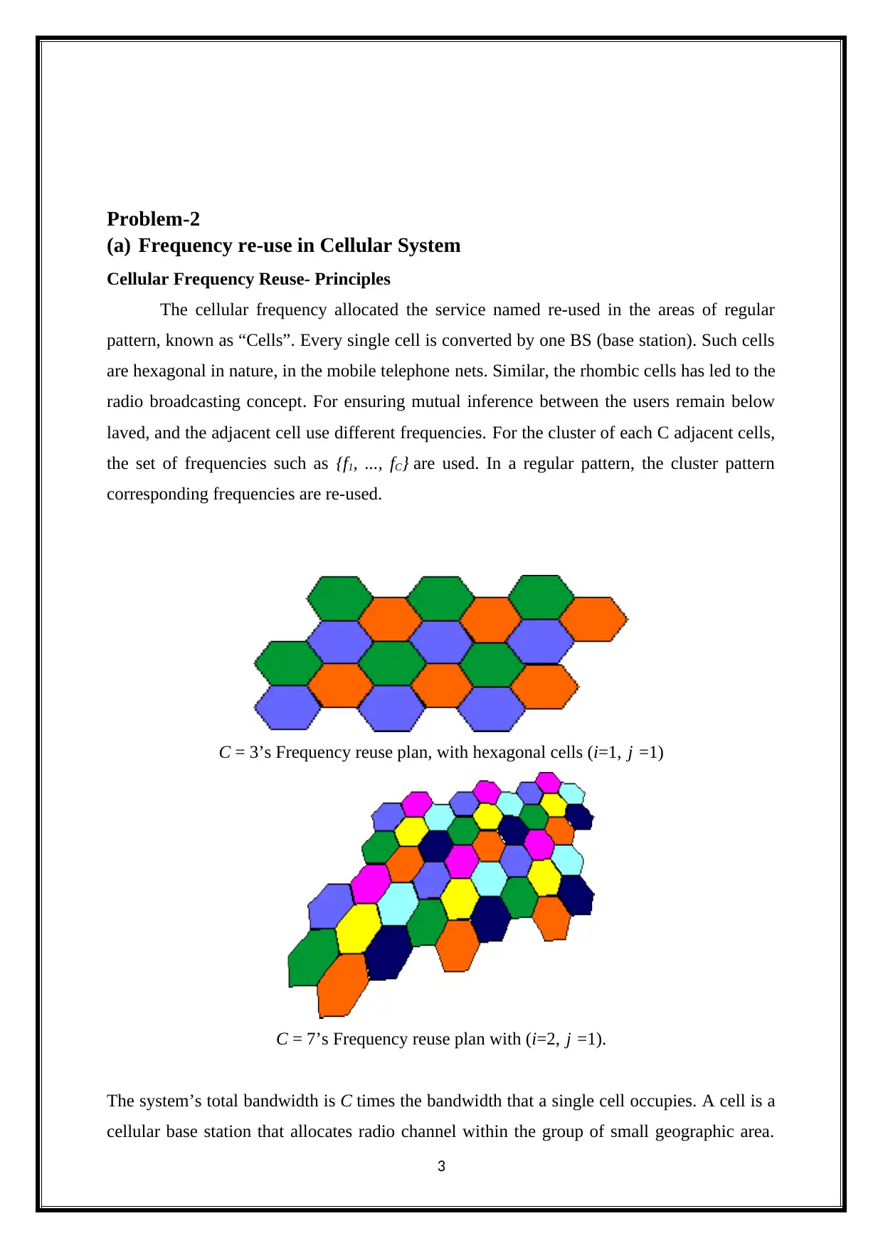
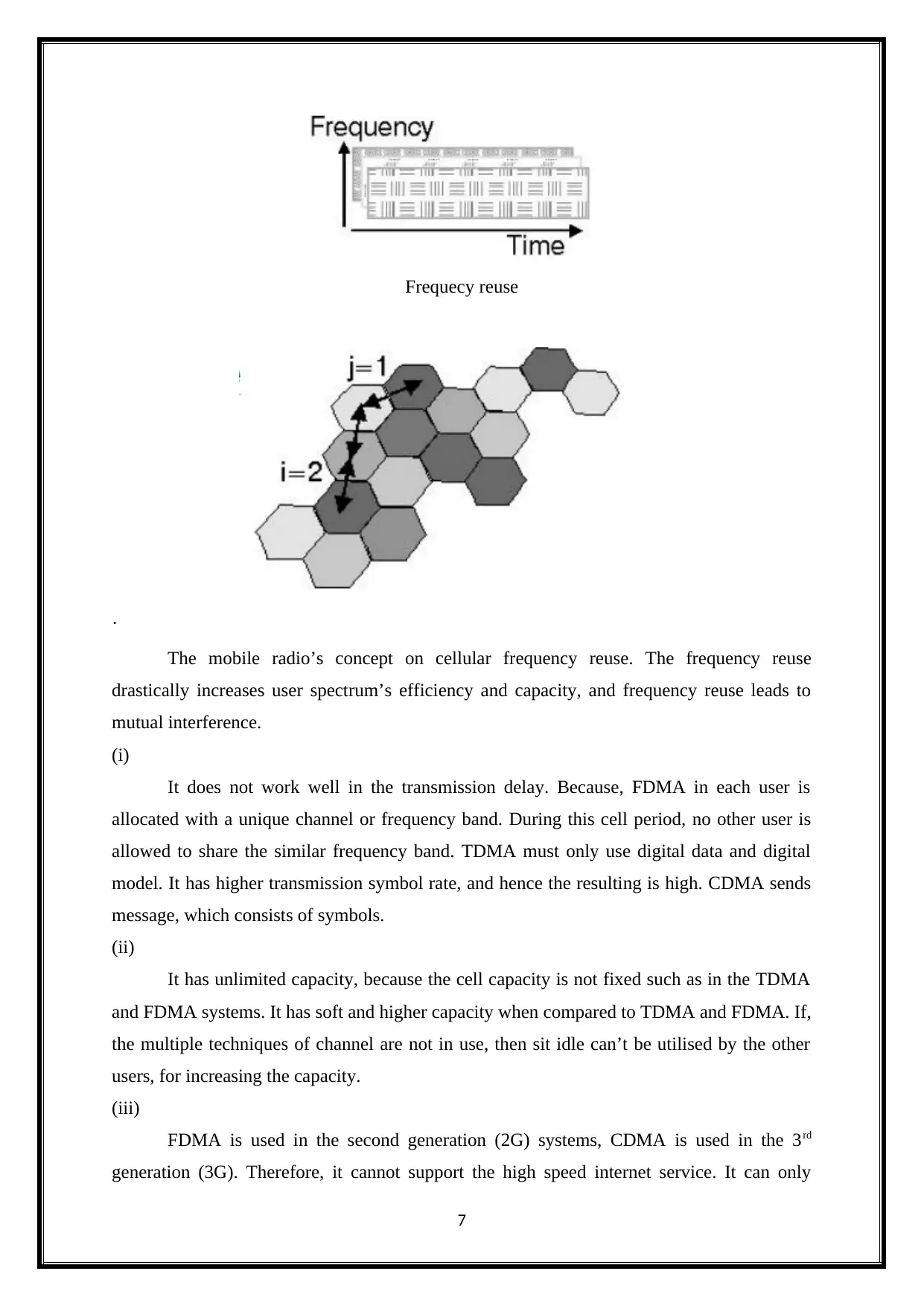
C = 3’s Frequency reuse plan, with hexagonal cells (i=1, j =1)
C = 7’s Frequency reuse plan with (i=2, j =1).
The system’s total bandwidth is C times the bandwidth that a single cell occupies. A cell is a
cellular base station that allocates radio channel within the group of small geographic area.
3
⊘ This is a preview!⊘
Do you want full access?
Subscribe today to unlock all pages.

Trusted by 1+ million students worldwide
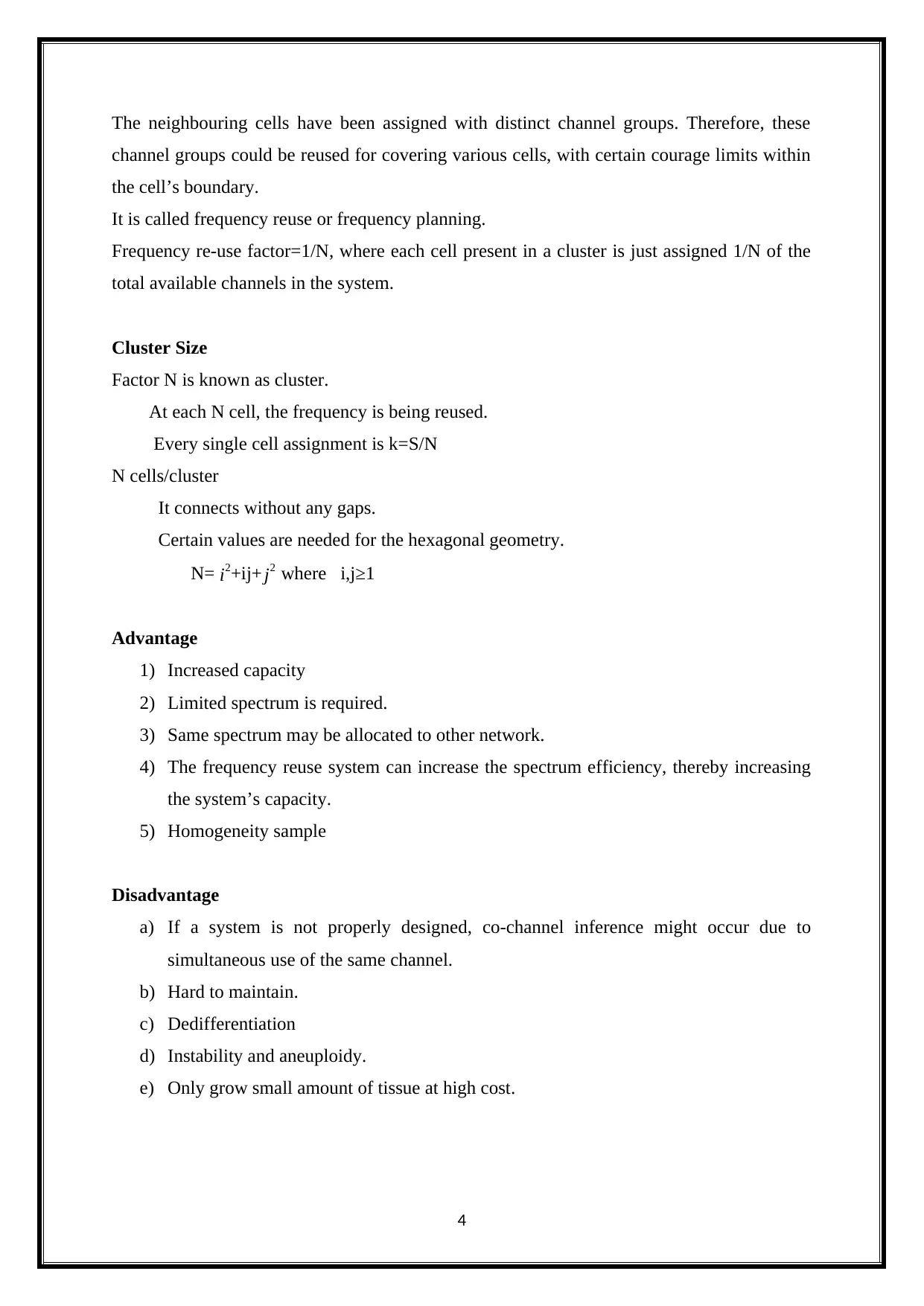
channel groups could be reused for covering various cells, with certain courage limits within
the cell’s boundary.
It is called frequency reuse or frequency planning.
Frequency re-use factor=1/N, where each cell present in a cluster is just assigned 1/N of the
total available channels in the system.
Cluster Size
Factor N is known as cluster.
At each N cell, the frequency is being reused.
Every single cell assignment is k=S/N
N cells/cluster
It connects without any gaps.
Certain values are needed for the hexagonal geometry.
N= i2+ij+ j2 where i,j≥1
Advantage
1) Increased capacity
2) Limited spectrum is required.
3) Same spectrum may be allocated to other network.
4) The frequency reuse system can increase the spectrum efficiency, thereby increasing
the system’s capacity.
5) Homogeneity sample
Disadvantage
a) If a system is not properly designed, co-channel inference might occur due to
simultaneous use of the same channel.
b) Hard to maintain.
c) Dedifferentiation
d) Instability and aneuploidy.
e) Only grow small amount of tissue at high cost.
4
Paraphrase This Document
It is electronic device which permits bi-directional (duplex) communication in a
single path. The radio communication system in radar isolates the transmitter from the
receiver, and allows sharing a common antenna. The radio repeater consists of a duplexer,
which might be based on frequency, polarization or timing.
To have two way communication (both voice and data), duplexing helps. It can allow
simultaneously to listen and talk.
The frequency or time domain technique can be used for duplexing.
The TDMA is a wired network, which uses high speed local area networking over the
existing home wiring. Thus, it can’t be utilized as duplex, in the celluar system.
(c) Multiple Access Technique
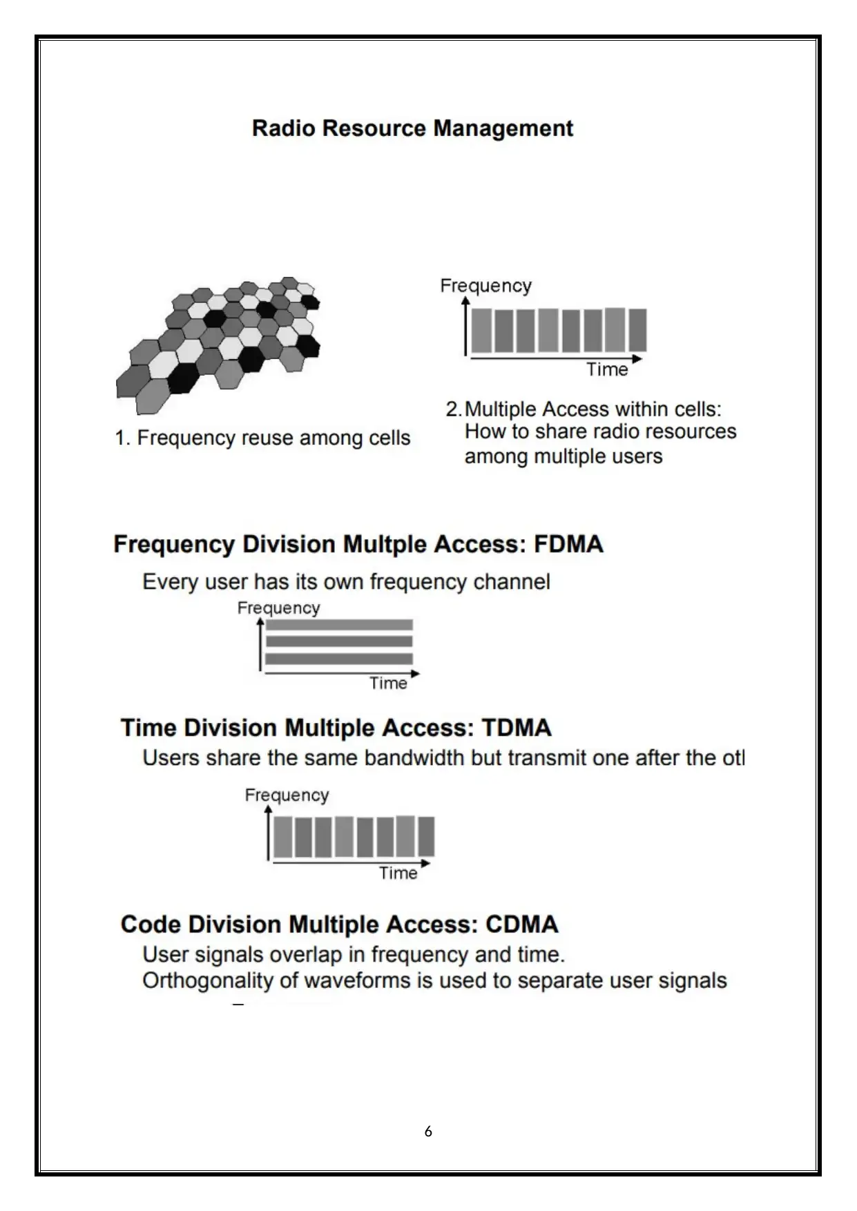
The multiple access technique is used to permit wide range of mobile users for
effectively sharing the allocated spectrum. The spectrum limited is sharing is required to
capacity cell increased the available band width to use at the same time by different users.
Multiple Access Techniques for Wireless Communication
The wireless communication system sends information to the BS, after receiving
information from the BS. Cellular system divides the given area into cells, like mobile units
in each communication cell with BS. The cellular system’s objective is to maximize the
channel’s capacity. It handles large number of calls, in sufficient level of quality service’s
bandwidth. These are various methods to permit the channels to have access.
The most used techniques are:
1) Frequency division multiple-access (FDMA)
2) Code division multiple-access (CDMA)
3) Time division multiple-access (TDMA)
5
⊘ This is a preview!⊘
Do you want full access?
Subscribe today to unlock all pages.

Trusted by 1+ million students worldwide
·
The mobile radio’s concept on cellular frequency reuse. The frequency reuse
drastically increases user spectrum’s efficiency and capacity, and frequency reuse leads to
mutual interference.
(i)
It does not work well in the transmission delay. Because, FDMA in each user is
allocated with a unique channel or frequency band. During this cell period, no other user is
allowed to share the similar frequency band. TDMA must only use digital data and digital
model. It has higher transmission symbol rate, and hence the resulting is high. CDMA sends
message, which consists of symbols.
(ii)
It has unlimited capacity, because the cell capacity is not fixed such as in the TDMA
and FDMA systems. It has soft and higher capacity when compared to TDMA and FDMA. If,
the multiple techniques of channel are not in use, then sit idle can’t be utilised by the other
users, for increasing the capacity.
(iii)
FDMA is used in the second generation (2G) systems, CDMA is used in the 3rd
generation (3G). Therefore, it cannot support the high speed internet service. It can only
7
Paraphrase This Document
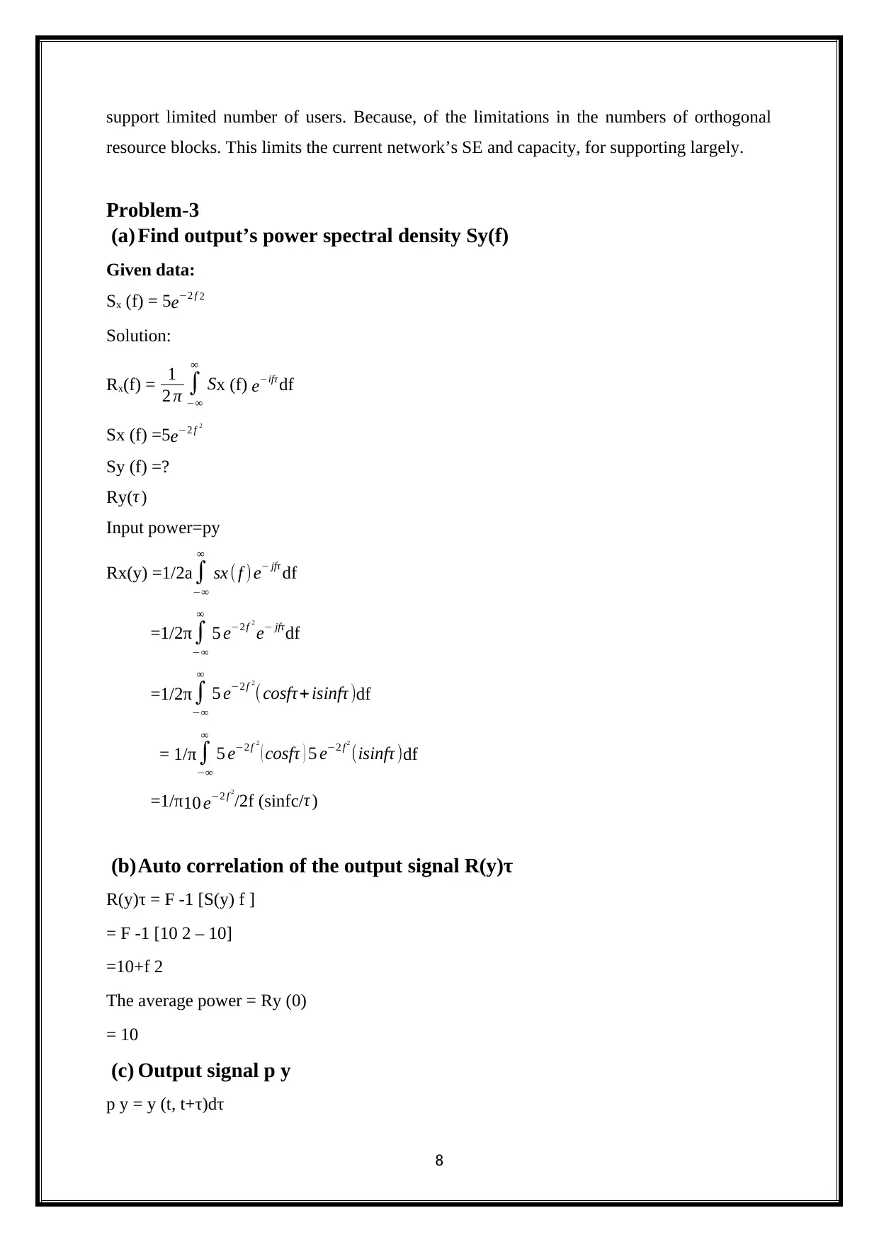
resource blocks. This limits the current network’s SE and capacity, for supporting largely.
Problem-3
(a) Find output’s power spectral density Sy(f)
Given data:
Sx (f) = 5e−2 f 2
Solution:
Rx(f) = 1
2 π ∫
−∞
∞
Sx (f) e−ifτ df
Sx (f) =5e−2 f 2
Sy (f) =?
Ry(τ )
Input power=py
Rx(y) =1/2a ∫
−∞
∞
sx ( f ) e− jfτ df
=1/2π∫
−∞
∞
5 e−2 f 2
e− jfτdf
=1/2π ∫
−∞
∞
5 e−2 f 2
( cosfτ+ isinfτ )df
= 1/π∫
−∞
∞
5 e−2 f 2
( cosfτ ) 5 e−2 f 2
(isinfτ )df
=1/π10 e−2 f 2
/2f (sinfc/τ )
(b)Auto correlation of the output signal R(y)τ
R(y)τ = F -1 [S(y) f ]
= F -1 [10 2 – 10]
=10+f 2
The average power = Ry (0)
= 10
(c) Output signal p y
p y = y (t, t+τ)dτ
8
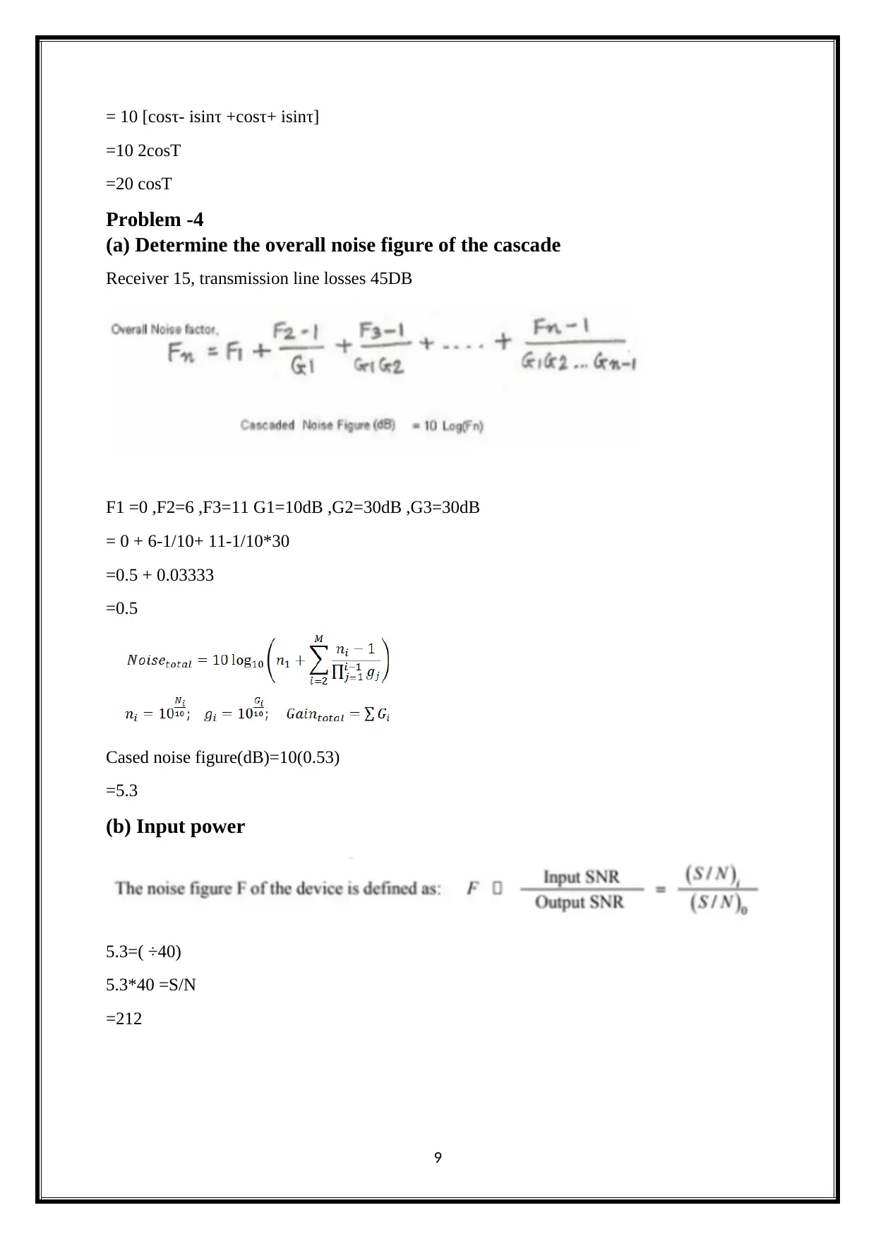
=10 2cosT
=20 cosT
Problem -4
(a) Determine the overall noise figure of the cascade
Receiver 15, transmission line losses 45DB
F1 =0 ,F2=6 ,F3=11 G1=10dB ,G2=30dB ,G3=30dB
= 0 + 6-1/10+ 11-1/10*30
=0.5 + 0.03333
=0.5
Cased noise figure(dB)=10(0.53)
=5.3
(b) Input power
5.3=( ÷40)
5.3*40 =S/N
=212
9
⊘ This is a preview!⊘
Do you want full access?
Subscribe today to unlock all pages.

Trusted by 1+ million students worldwide
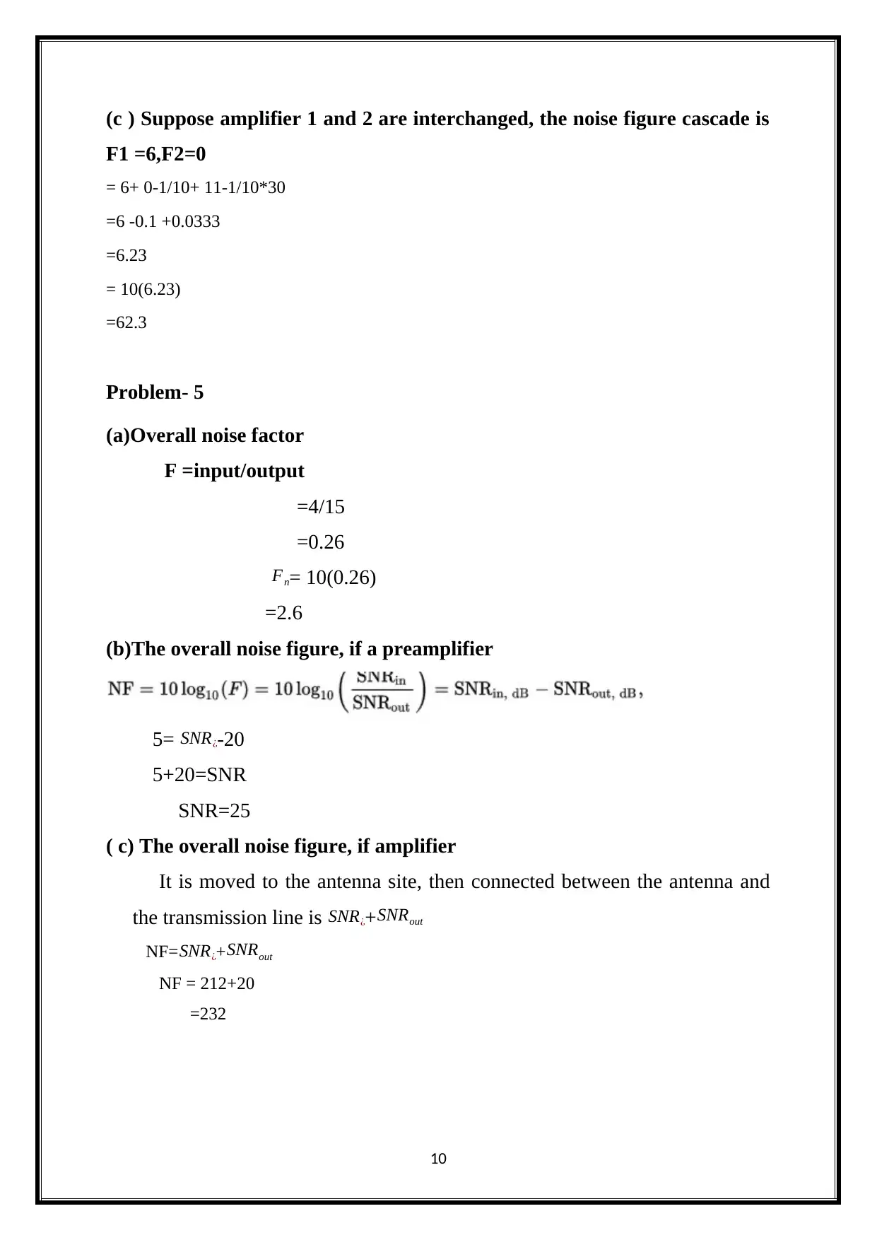
F1 =6,F2=0
= 6+ 0-1/10+ 11-1/10*30
=6 -0.1 +0.0333
=6.23
= 10(6.23)
=62.3
Problem- 5
(a)Overall noise factor
F =input/output
=4/15
=0.26
Fn= 10(0.26)
=2.6
(b)The overall noise figure, if a preamplifier
5= SNR¿-20
5+20=SNR
SNR=25
( c) The overall noise figure, if amplifier
It is moved to the antenna site, then connected between the antenna and
the transmission line is SNR¿+ SNRout
NF= SNR¿+ SNRout
NF = 212+20
=232
10
Paraphrase This Document
(a) Auto correlation function
Y (t) =A [cos (2πf o t+Ѳ1) - sin (2πf o t+Ѳ2)]
X (t) =h (t)*y (t)
Rx (t) =lim1/T [cos (2π f o ¿+τ ¿+Ѳ1) - sin (2π f o ¿+τ ¿+Ѳ2)]dt
= [sin (2π∞2π f o ¿+τ ¿+Ѳ1)/f o ¿+τ ¿ - cos (2πf o ¿+τ ¿+Ѳ2/f o ¿+τ ¿
= [sin2π + Ѳ1- cos 2π +Ѳ2 ¿
Rx (t) = [sin2π + Ѳ1- cos 2π +Ѳ2 ¿
(b)Power spectral density
Sx (f) =sy (f)/ ¿ H (f )∨¿2 ¿
Problem – 7
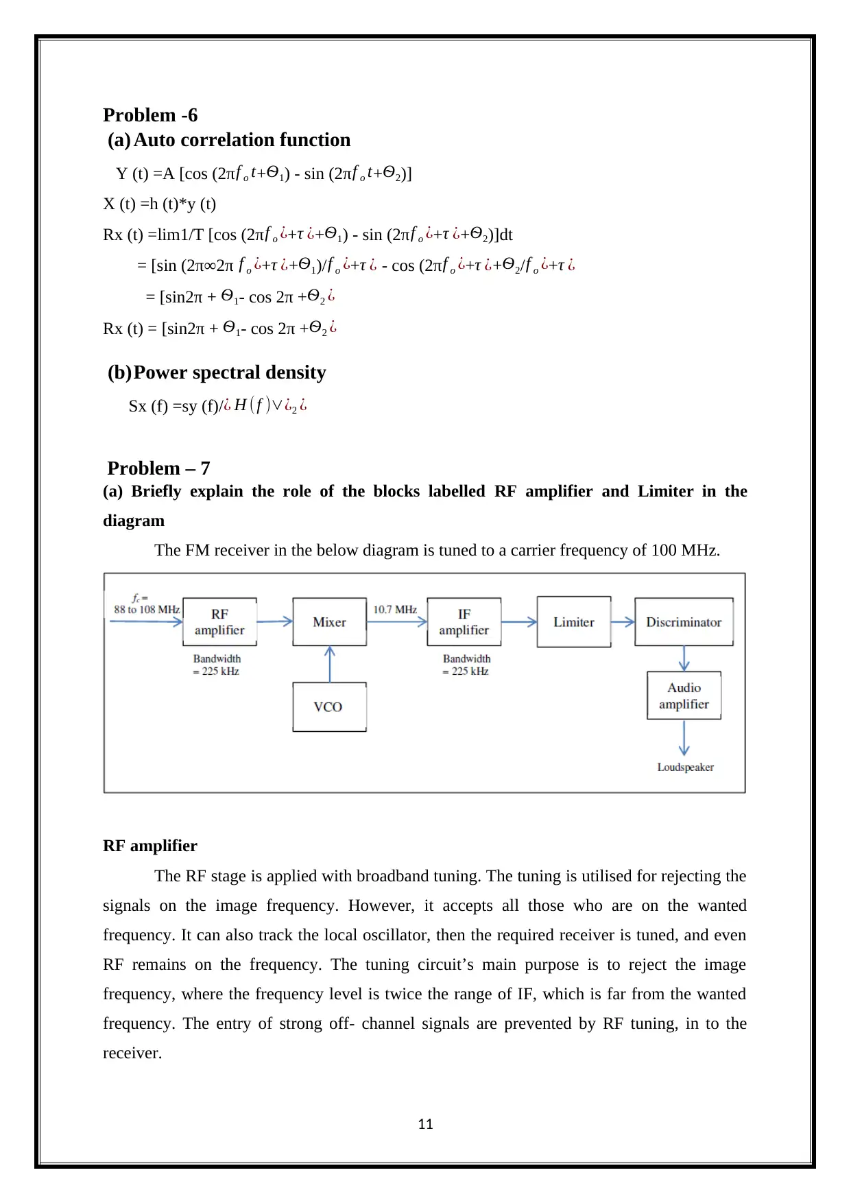
(a) Briefly explain the role of the blocks labelled RF amplifier and Limiter in the
diagram
The FM receiver in the below diagram is tuned to a carrier frequency of 100 MHz.
RF amplifier
The RF stage is applied with broadband tuning. The tuning is utilised for rejecting the
signals on the image frequency. However, it accepts all those who are on the wanted
frequency. It can also track the local oscillator, then the required receiver is tuned, and even
RF remains on the frequency. The tuning circuit’s main purpose is to reject the image
frequency, where the frequency level is twice the range of IF, which is far from the wanted
frequency. The entry of strong off- channel signals are prevented by RF tuning, in to the
receiver.
11
radio frequency signal. Generally, the RF power amplifier drives the transmitter’s antenna. It
is designed to contain output of gain and power; bandwidth; power efficiency linearity (low
signal compression at rated output) output and matching input impedance; and heat
dissipation. Radio frequency amplifier are the tuned amplifiers, where the tuned circuit
governs frequency’s operations. This circuit cannot adjusted based on the amplifier’s needs.
The bandwidth also depends on its usage. It might either be wide or narrow.
Amplification
The amplification is used to choose the mixer, in the presence of strong signals, yet it
allows sufficient amplification of the signals. The amplifier could be denoted as a low noise
design.
Mixer
The mixer is a port where the tuned and amplified signals enter. The local oscillator
signal enters another port. The complete performance of the receiver matters with the
performance of the mixer.
Local Oscillator
The variable oscillator is encompassed in the local oscillator, where the variable
capacitor’s settings can altered for tuning. It is also known for frequency synthesizing, which
empowers high stability levels and accuracy of the setting.
IF amplifier
Once the signal enters into the mixer, it enters the IF stages. The IF stages consists
both amplification and filtering, in the receiver. The filters consist of simple LC tuned
transformers. It provides inter-stage coupling or ceramic or crystal filters.
Demodulator stage
When the IF stage signals are allowed to pass through the receiver, these signals must
be demodulated. For various sorts of transmission, different demodulators are essential. The
following demodulators are used:
a) quadrature FM detector
b) AM diode detector
c) SSB product detector
d) synchronous AM detector
e) PLL FM detector
12
⊘ This is a preview!⊘
Do you want full access?
Subscribe today to unlock all pages.

Trusted by 1+ million students worldwide
Audio Amplifier
The output signal from the demodulator signal is recovered by using the audio
amplifier. The audio amplifier is passed into the amplifier and are sent to the headphones or
to the loud speakers.
Limiter
The limiter circuit limits the signals, below the mentioned input power. Dynamic
range compression is a type of limiting. The clipping circuit is limiting’s extreme version.
Generally, limiting is utilised for preventing from exceeding the predetermined value, in any
process of the device’s output. For preventing sudden volume peaks, the limiter functions as a
common safety device. In some of the sound reinforcement systems, the limiters are added as
the protective features such as, mixing boards and power amplifiers, and for preventing
unrequired distortion.
Types of limiter
The limiting circuit denotes the non-linear clipping, where the signal is normally
passed, but it will "sheared off". Limiting circuit also refers the audio level compression,
which instantly changes the amplifier’s gain. The limiter is categorised as follows:
1) Hard Limiting
2) Soft Limiting
Hard limiting
This type of limiting permits dynamic range of output signal. The steady state signal
is the permitted level for each period’s duration. It requires output for exceeding the
permitted dynamic range, for transferring the device’s function.
Soft limiting
This type of limiting is considered as a transfer function of its integrated output level.
The output waveform is not clipped but distorted (Alencar, M 2014).
In amplifiers
The limiting circuit is commonly equipped with the power amplifier and bass
instrument amplifiers. The electric guitar amplifiers don’t certainly contain the limiters. The
PIN diodes could be utilised for reflecting the source’s energy back.
In FM radio
13
Paraphrase This Document
demodulator with constant level of signal. Thus, simultaneously two or more signals are
received. High performance of a limiter declines the weaker signal’s effect. FM radio signals
are broadly known for its capturing effect. The amplitude variations are left unaffected by the
FM demodulators. The information of amplitude variation is also used located in the AM
radio. The spurious signals can be the reason for distortion.
(b) Find the bandwidths required for the RF amplifier, IF amplifier, and of the audio
amplifier
Given data:
Carrier frequency = 100MHz
Modulated frequency = 10 kHZ
RF amplifier
Bandwidth BW = 2fm
= 2(10000)
Bandwidth BW =20000
IF amplifier
Bandwidth BW = fc-2fm
=1000000-2(10000)
=980000
Audio frequency
Bandwidth BW = 2βfm
=2(5)(10000)
=100000
(c) Larger bandwidth
Given data:
Modulated signal fm1 = 10 kHz
Gain β1 = 5
Modulated signal fm2 = 2kHz
Gain β2 = 25
Solution:
14
=2(8)(10000)
=160000
Bandwidth BW2 =2nfm
=2(50)(2000)
=200000
Problem- 8
(a) Briefly explain what is meant by an ergodic random process
Ergodic process
In ergodic processes the time and the ensemble averages cannot be interchanged. The
ergodic process deals with the quality of time and statistical averages. A random process X (t)
is an ergodic random variable, if the ensemble averages are equivalent to the time averages.
E[X (t)] = XT where XT = 1
2T ∫
−T
T
X ( t ) dt
Time average
The time average is expressed as follows,
It is denoted as XT .
XT = 1
2T ∫
−T
T
X ( t ) dt , X (t) defined in (-T, T)
XT = 1
T ∫
0
T
X (t ) dt, X (t) defined in (0, T)
Ensemble average
The ensemble average of a random process of ergodic process {X(t)} is the expected
value of the random number X, at time t.
Ensemble average = E[X (t)]
Mean-Ergodic process
The mean-Ergodic process is expressed as follows
E[X (t)] = lim
T → ∞
1
2T ∫
−T
T
X (t) dt is constant (or)
Prove lim
T → ∞
¿ var (XT) = 0.
Mean-Square ergodic (or) power ergodic
The mean-Square ergodic is called as X (t), and it is denoted as R (0).
15
⊘ This is a preview!⊘
Do you want full access?
Subscribe today to unlock all pages.

Trusted by 1+ million students worldwide
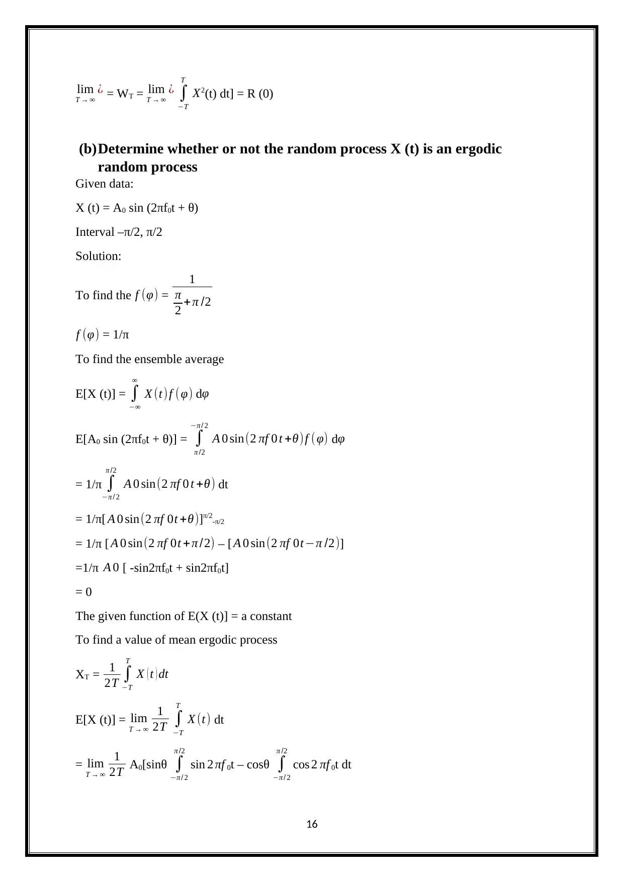
T → ∞
¿ = WT = lim
T → ∞
¿ ∫
−T
T
X2(t) dt] = R (0)
(b)Determine whether or not the random process X (t) is an ergodic
random process
Given data:
X (t) = A0 sin (2πf0t + θ)
Interval –π/2, π/2
Solution:
To find the f (φ) =
1
π
2 +π /2
f (φ) = 1/π
To find the ensemble average
E[X (t)] = ∫
−∞
∞
X (t)f (φ) dφ
E[A0 sin (2πf0t + θ)] = ∫
π /2
−π / 2
A 0 sin(2 πf 0 t +θ)f ( φ) dφ
= 1/π ∫
−π / 2
π /2
A 0 sin(2 πf 0 t +θ) dt
= 1/π[ A 0 sin(2 πf 0t +θ)]π/2-π/2
= 1/π [ A 0 sin(2 πf 0t +π /2) – [ A 0 sin(2 πf 0t−π /2)]
=1/π A 0 [ -sin2πf0t + sin2πf0t]
= 0
The given function of E(X (t)] = a constant
To find a value of mean ergodic process
XT = 1
2T ∫
−T
T
X ( t ) dt
E[X (t)] = lim
T → ∞
1
2T ∫
−T
T
X (t) dt
= lim
T → ∞
1
2T A0[sinθ ∫
−π / 2
π /2
sin 2 πf 0t – cosθ ∫
−π / 2
π /2
cos 2 πf 0t dt
16
Paraphrase This Document
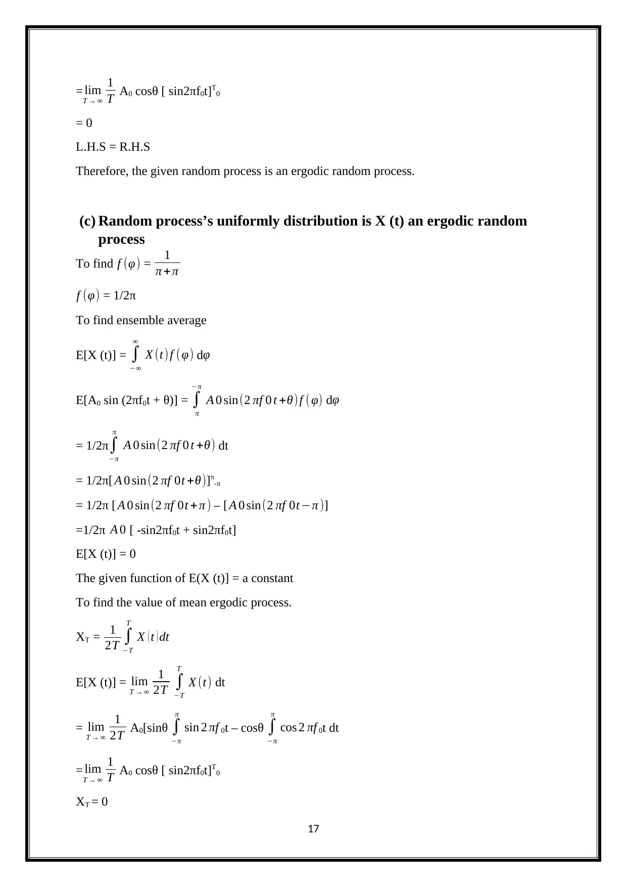
T → ∞
1
T A0 cosθ [ sin2πf0t]T0
= 0
L.H.S = R.H.S
Therefore, the given random process is an ergodic random process.
(c) Random process’s uniformly distribution is X (t) an ergodic random
process
To find f (φ) = 1
π + π
f (φ) = 1/2π
To find ensemble average
E[X (t)] = ∫
−∞
∞
X (t)f (φ) dφ
E[A0 sin (2πf0t + θ)] = ∫
π
−π
A 0 sin(2 πf 0 t +θ) f ( φ) dφ
= 1/2π∫
−π
π
A 0 sin(2 πf 0 t +θ) dt
= 1/2π[ A 0 sin(2 πf 0t +θ)]π-π
= 1/2π [ A 0 sin(2 πf 0t + π ) – [ A 0 sin(2 πf 0t−π )]
=1/2π A 0 [ -sin2πf0t + sin2πf0t]
E[X (t)] = 0
The given function of E(X (t)] = a constant
To find the value of mean ergodic process.
XT = 1
2T ∫
−T
T
X ( t ) dt
E[X (t)] = lim
T → ∞
1
2T ∫
−T
T
X (t) dt
= lim
T → ∞
1
2T A0[sinθ ∫
−π
π
sin 2 πf 0t – cosθ ∫
−π
π
cos 2 πf 0t dt
= lim
T → ∞
1
T A0 cosθ [ sin2πf0t]T0
XT = 0
17
References
Alencar, M. (2014). Communication systems. [Place of publication not identified]: Springer.
Integrated Publishing, I. (2017). BANDWIDTH OF AN AMPLIFIER - 14180_55. [online]
Electriciantraining.tpub.com. Available at:
http://electriciantraining.tpub.com/14180/css/Bandwidth-Of-An-Amplifier-55.htm
[Accessed 23 Nov. 2017].
18
⊘ This is a preview!⊘
Do you want full access?
Subscribe today to unlock all pages.

Trusted by 1+ million students worldwide
Your All-in-One AI-Powered Toolkit for Academic Success.
+13062052269
info@desklib.com
Available 24*7 on WhatsApp / Email
![[object Object]](/_next/static/media/star-bottom.7253800d.svg)
© 2024 | Zucol Services PVT LTD | All rights reserved.