Object Localization and Robot Navigation
VerifiedAdded on  2020/03/16
|11
|1683
|152
AI Summary
This project focuses on object localization and robot navigation through a combination of computer vision and sensor data processing. It involves two main components: 1) Object Localization: Utilizing centroid-based vision algorithms to determine the distance of objects from a camera based on their bounding box size and real-time coordinates. 2) SLAM (Simultaneous Localization and Mapping): Implementing grid mapping techniques using sensor data and wheel encoder readings to track the robot's position within its environment. The project highlights the challenges of GPS inaccuracy and proposes solutions like dead reckoning and sensor fusion for robust localization.
Contribute Materials
Your contribution can guide someone’s learning journey. Share your
documents today.
Competency Demonstration Report
Career Episode 3
Career Episode 3
Secure Best Marks with AI Grader
Need help grading? Try our AI Grader for instant feedback on your assignments.
CE 3.1 Project Information
Name of the project: Development of localizing algorithm for the position estimation of
mobile robot
Location of the project: (Please fill)
Project Duration: (Please fill)
Organization: (Please fill)
Role and Designation during the time: Team Member
CE 3.2 Project Background
CE 3.2.1 Characteristics of the project
I had conducted the project on developing localization of algorithm for the position
estimation of the mobile robot. Localization into the industry is used of algorithm scheme.
Localization is become a problem when GPS signals are being blocked due to unavailability of
the sky view. Different types of algorithms are being used in order to localize the indoor vehicle
and robot but its outcomes are good cost for purpose of installation. The application area of this
project work was unmanned ground vehicle (UGV) requirements for estimation of the position.
Tracking of target, obstacle avoider and path finder are required modifications to create
algorithm. The modifications are allowed due to use of webcams.
CE 3.2.2 Objectives developed for the project
Following are the objectives of this project study:
ï‚· To develop of localizing algorithm for the position estimation of mobile robot
ï‚· To identify the application areas of localization
ï‚· To use of MATLAB for image and video processing and PROTEUS for supporting real
world components
ï‚· To design a mobile robot controlled with wired remote control
CE 3.2.3 My area of work
I had designed the mobile robot by means of wired remote control. This robot captures
live video with help of 2 webcams. I had connected the webcams with long wire to the base
station laptop which is running on the windows. I had used of MATLAB for detecting the object
using Colored object detector. I had then measured the distance between camera as well as object
with use of algorithm. I had executed this process using snapshots of wall of the arena. For the
second wall, I had executed the same method. 2-4 walls are used to detect the object. 2-4
coordinates are being obtained by algorithm and remaining is subtracted by found coordinate. In
the same way, 4 coordinates are being acquired as per the project objective.
CE 3.2.4 Project Group
ProjectSupervisorElectronicsEngineerElectronicsEngineerElectronicsEngineer
Figure 1: People involved in the project
CE 3.2.5 My responsibilities throughout the project
I had used of MATLAB for image and video processing and performed hardware and
software design for localization of algorithm for the position estimation of mobile robot. I had to
attempt of algorithm to cut higher cost for localization scheme as well as offer of better
algorithm to obtain accuracy into the coordinates.
CE 3.3 Distinctive Activity
CE 3.3.1 Comprehending the Theory of the project
In order to construct map of unknown surroundings and revise of the map as per the
changes occurred; I had used of Simultaneous localization and mapping (SLAM). Localization
of the robot is defined as finding position for the robot. I had kept the position of robot at a
landmark. A localization technique provides accurate results into one environment. The
localization techniques provide information such as location of the robot and continuing
orientation of the robot. I had found the location of the robot from the geographic longitude as
well as latitude, polar as well as Cartesian coordinates. I had followed various methods to
determine current location of the robot form.
CE 3.3.2 Engineering Knowledge and Skills applied in the project
I had knowledge to use of MATLAB for image and video processing to estimate the
position of the mobile robot. I had followed two of the design approaches to estimate the
Paraphrase This Document
Need a fresh take? Get an instant paraphrase of this document with our AI Paraphraser
position. Design approach 1: I had put a complete running operating system such a laptop on the
robot. It is considered as the first stage as it is essential to start case as basic testing, which is
performed on MATLAB and fro the development of the visual environments. The benefit of this
approach is to transfer of data using wireless local area network. Design approach 2: I had fitted
sensor as well as cameras to the vehicle. The base station is responsible to perform processing.
The vehicles are small in size and the products are presented as plug and play. There is no
requirement to install it. If there is breakage of connection to the base station, then the robot is of
no use. At the time of transmission of video, we had used microcontroller and video camera is
used to make interface and send video throughout the medium.
CE 3.3.3 Accomplishment and task performed
Our fyp team had developed of two algorithms for the position estimation of the mobile
robot.
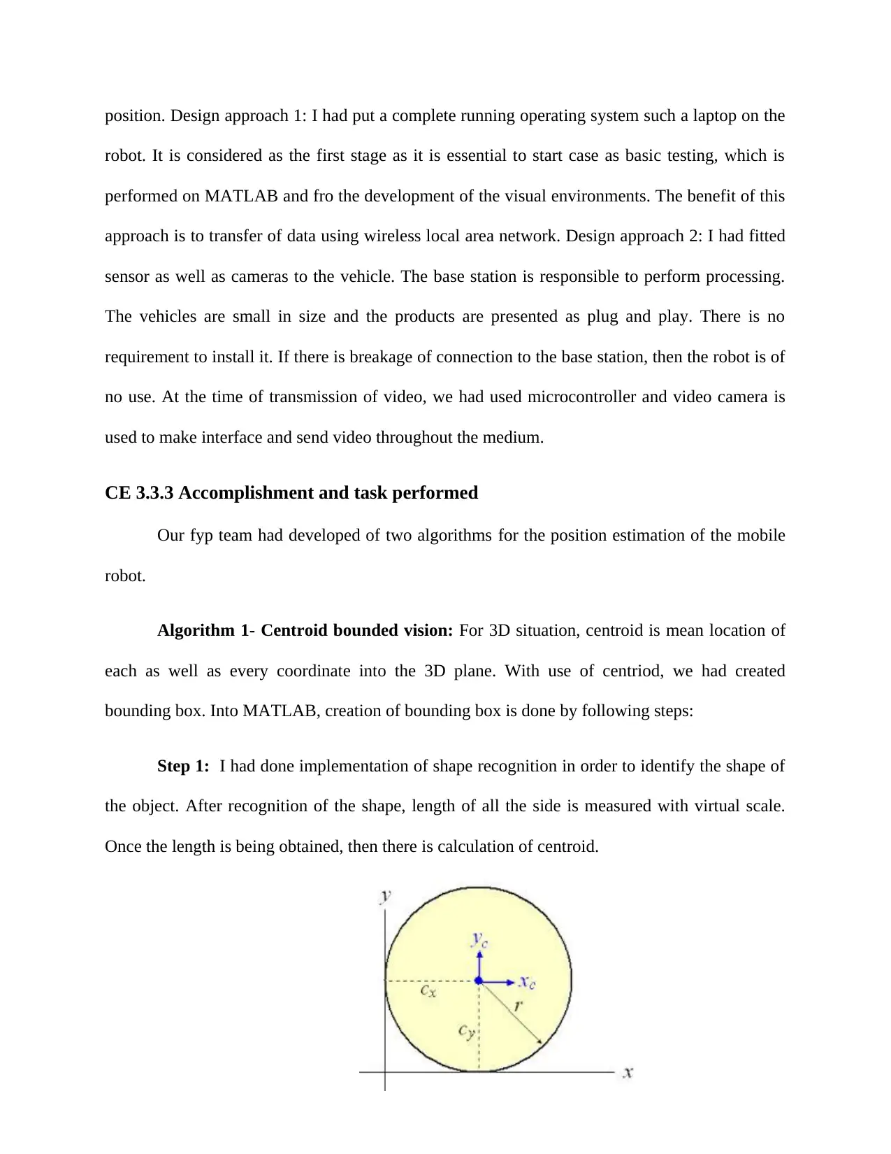
Algorithm 1- Centroid bounded vision: For 3D situation, centroid is mean location of
each as well as every coordinate into the 3D plane. With use of centriod, we had created
bounding box. Into MATLAB, creation of bounding box is done by following steps:
Step 1: I had done implementation of shape recognition in order to identify the shape of
the object. After recognition of the shape, length of all the side is measured with virtual scale.
Once the length is being obtained, then there is calculation of centroid.
Figure 2: Centroid of the circle
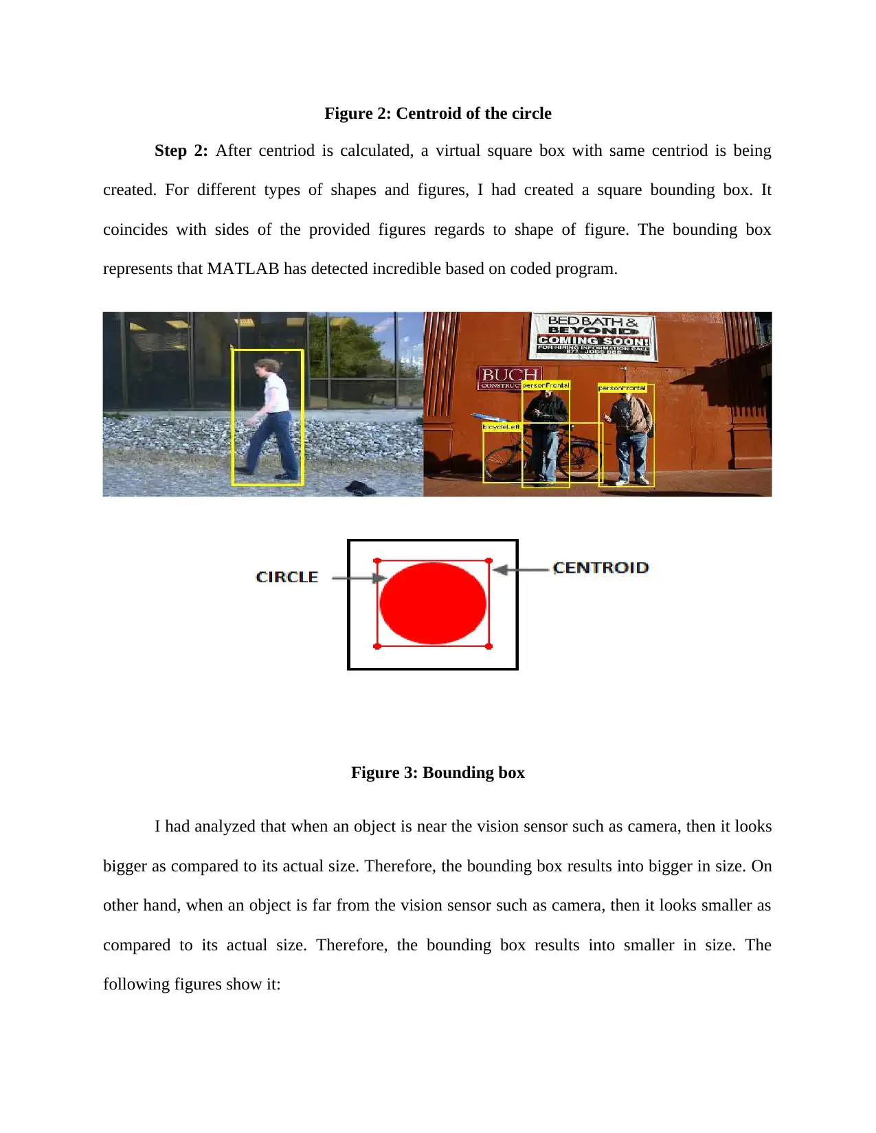
Step 2: After centriod is calculated, a virtual square box with same centriod is being
created. For different types of shapes and figures, I had created a square bounding box. It
coincides with sides of the provided figures regards to shape of figure. The bounding box
represents that MATLAB has detected incredible based on coded program.
Figure 3: Bounding box
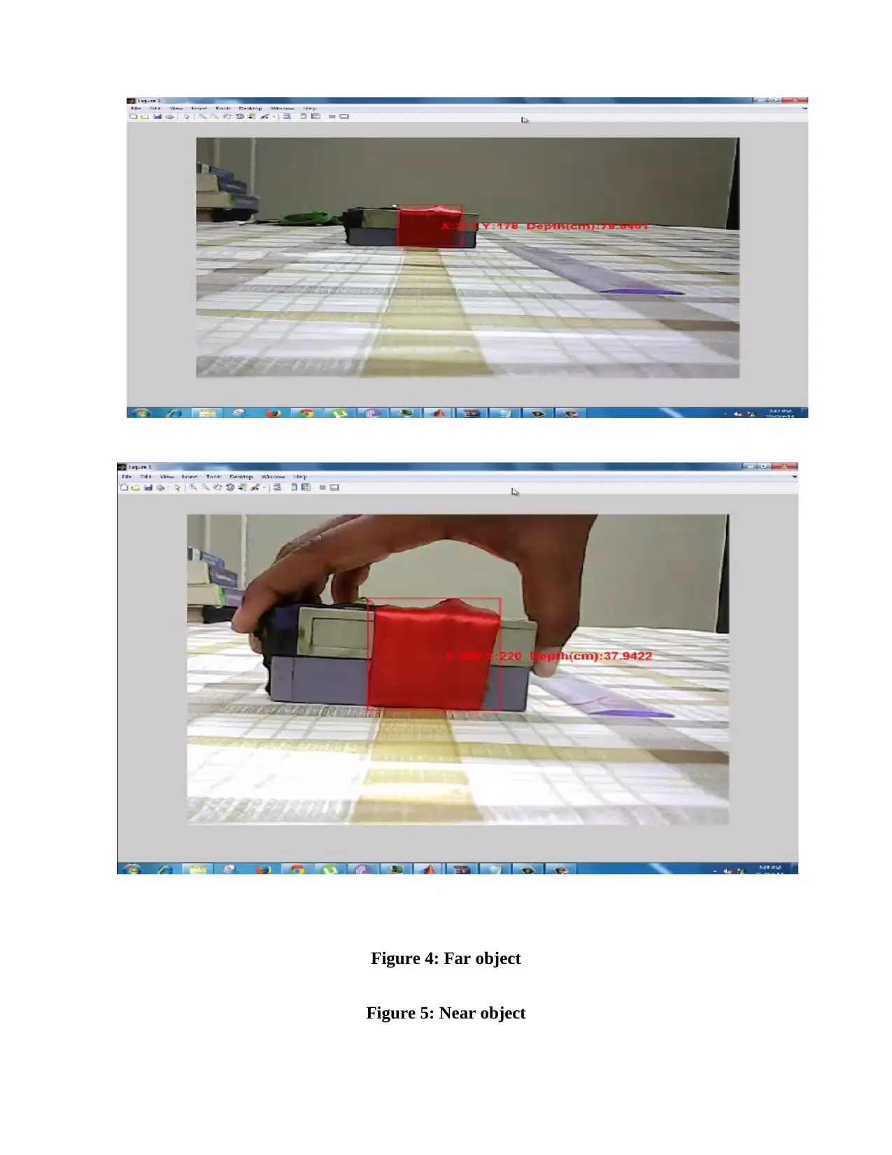
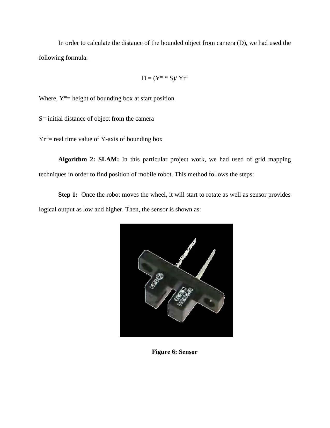
I had analyzed that when an object is near the vision sensor such as camera, then it looks
bigger as compared to its actual size. Therefore, the bounding box results into bigger in size. On
other hand, when an object is far from the vision sensor such as camera, then it looks smaller as
compared to its actual size. Therefore, the bounding box results into smaller in size. The
following figures show it:
Figure 4: Far object
Figure 5: Near object
Secure Best Marks with AI Grader
Need help grading? Try our AI Grader for instant feedback on your assignments.
In order to calculate the distance of the bounded object from camera (D), we had used the
following formula:
D = (Ym * S)/ Yrm
Where, Ym= height of bounding box at start position
S= initial distance of object from the camera
Yrm= real time value of Y-axis of bounding box
Algorithm 2: SLAM: In this particular project work, we had used of grid mapping
techniques in order to find position of mobile robot. This method follows the steps:
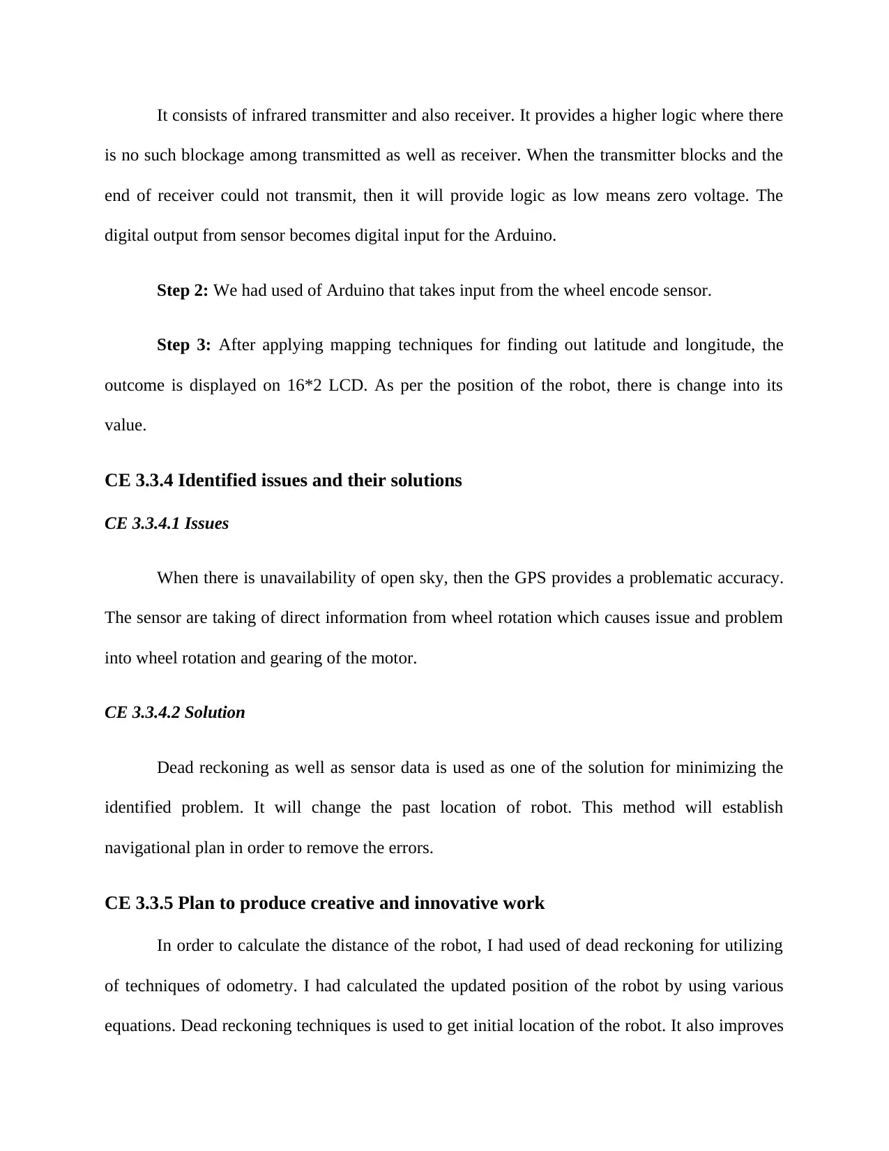
Step 1: Once the robot moves the wheel, it will start to rotate as well as sensor provides
logical output as low and higher. Then, the sensor is shown as:
Figure 6: Sensor
It consists of infrared transmitter and also receiver. It provides a higher logic where there
is no such blockage among transmitted as well as receiver. When the transmitter blocks and the
end of receiver could not transmit, then it will provide logic as low means zero voltage. The
digital output from sensor becomes digital input for the Arduino.
Step 2: We had used of Arduino that takes input from the wheel encode sensor.
Step 3: After applying mapping techniques for finding out latitude and longitude, the
outcome is displayed on 16*2 LCD. As per the position of the robot, there is change into its
value.
CE 3.3.4 Identified issues and their solutions
CE 3.3.4.1 Issues
When there is unavailability of open sky, then the GPS provides a problematic accuracy.
The sensor are taking of direct information from wheel rotation which causes issue and problem
into wheel rotation and gearing of the motor.
CE 3.3.4.2 Solution
Dead reckoning as well as sensor data is used as one of the solution for minimizing the
identified problem. It will change the past location of robot. This method will establish
navigational plan in order to remove the errors.
CE 3.3.5 Plan to produce creative and innovative work
In order to calculate the distance of the robot, I had used of dead reckoning for utilizing
of techniques of odometry. I had calculated the updated position of the robot by using various
equations. Dead reckoning techniques is used to get initial location of the robot. It also improves
the entire accuracy of the technique. GPS is used to provide accurateness into polar and
Cartesian coordinates. It provides of problematic accuracies. In order to provide localization,
dead reckoning as well as sensor data are becomes a source.
Cartesian coordinates. It provides of problematic accuracies. In order to provide localization,
dead reckoning as well as sensor data are becomes a source.
Paraphrase This Document
Need a fresh take? Get an instant paraphrase of this document with our AI Paraphraser
CE 3.3.6 Collaborative work
My team members helped me into calculation part for this project work. I had followed
the project schedule to end the activities on scheduled time so that there are no chances of late
submission. My project supervisor suggested and advised me when I had faced any issues.
CE 3.4 Project review
CE 3.4.1 Project overview
The algorithm is used to cut the higher cost of the localization scheme and provide of best
algorithm to obtain of better accurateness into the coordinates.
CE 3.4.2 My contribution to work
I had calculated the distance between camera as well as object with use of two types of
algorithms such as Centroid bounded vision and SLAM. I had executed this process using
snapshots of wall of the arena.
1 out of 11
Related Documents
Your All-in-One AI-Powered Toolkit for Academic Success.
 +13062052269
info@desklib.com
Available 24*7 on WhatsApp / Email
Unlock your academic potential
© 2024  |  Zucol Services PVT LTD  |  All rights reserved.