Electrical & Electronic Principles: TMA 3 on Complex Waveforms
VerifiedAdded on 2023/06/11
|14
|2323
|331
Homework Assignment
AI Summary
This assignment solution covers complex waveforms and transients in R-L-C circuits, addressing topics such as Fourier series, symmetry conditions (even, odd, and half-wave), and total harmonic distortion (THD). It includes calculations of power dissipation, analysis of symmetrical waveforms in rectifiers, and synthesis of original waveforms. The solution also delves into the transient response of circuits with varying damping ratios and natural frequencies, and applies Laplace transforms to solve circuit problems. Nodal analysis is used to derive transfer functions and analyze circuit behavior, providing a comprehensive overview of electrical and electronic principles related to complex waveforms and transients. Desklib offers a wealth of similar solved assignments and past papers for students.
MODULE TITLE : ELECTRICAL AND ELECTRONIC PRINCIPLES
TOPIC TITLE : COMPLEX WAVEFORMS & TRANSIENTS IN R-L-C CIRCUITS
TUTOR MARKED ASSIGNMENT 3 (v3.1)
Q1)
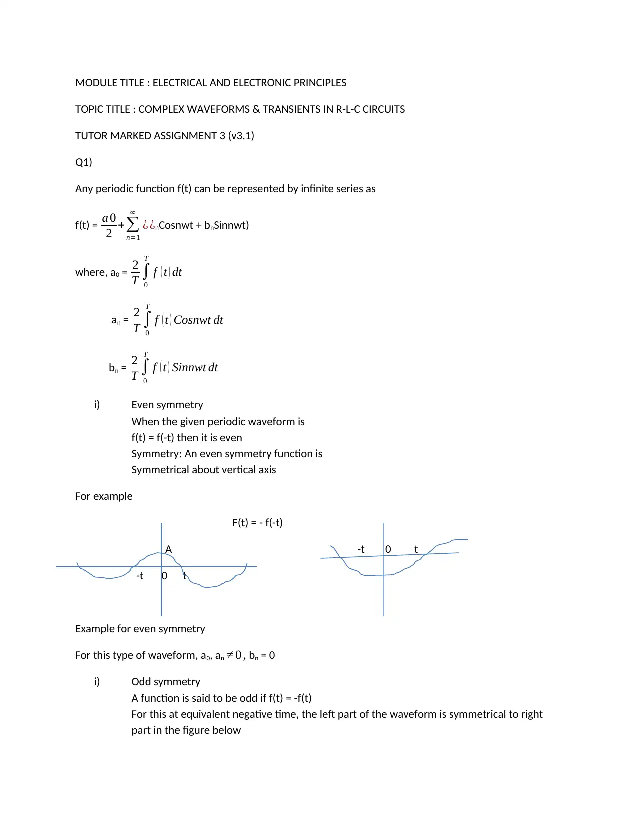
Any periodic function f(t) can be represented by infinite series as
f(t) = a 0
2 +∑
n=1
∞
¿ ¿nCosnwt + bnSinnwt)
where, a0 = 2
T ∫
0
T
f ( t ) dt
an = 2
T ∫
0
T
f ( t ) Cosnwt dt
bn = 2
T ∫
0
T
f ( t ) Sinnwt dt
i) Even symmetry
When the given periodic waveform is
f(t) = f(-t) then it is even
Symmetry: An even symmetry function is
Symmetrical about vertical axis
For example
F(t) = - f(-t)
A -t 0 t
-t 0 t
Example for even symmetry
For this type of waveform, a0, an ≠ 0 , bn = 0
i) Odd symmetry
A function is said to be odd if f(t) = -f(t)
For this at equivalent negative time, the left part of the waveform is symmetrical to right
part in the figure below
Paraphrase This Document
Need a fresh take? Get an instant paraphrase of this document with our AI Paraphraser
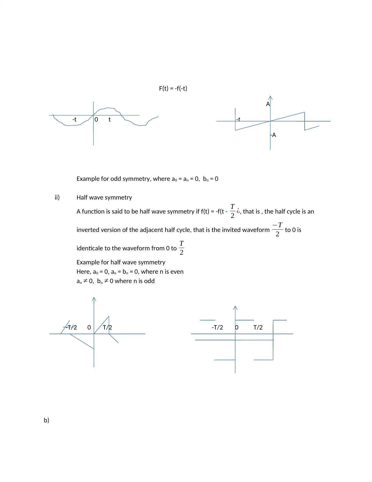
F(t) = -f(-t)
A
-t 0 t -t
-A
Example for odd symmetry, where a0 = an = 0, bn = 0
ii) Half wave symmetry
A function is said to be half wave symmetry if f(t) = -f(t - T
2 ¿, that is , the half cycle is an
inverted version of the adjacent half cycle, that is the invited waveform −T
2 to 0 is
identicale to the waveform from 0 to T
2
Example for half wave symmetry
Here, a0 = 0, an = bn = 0, where n is even
an ≠ 0, bn ≠ 0 where n is odd
-T/2 0 T/2 -T/2 0 T/2
b)
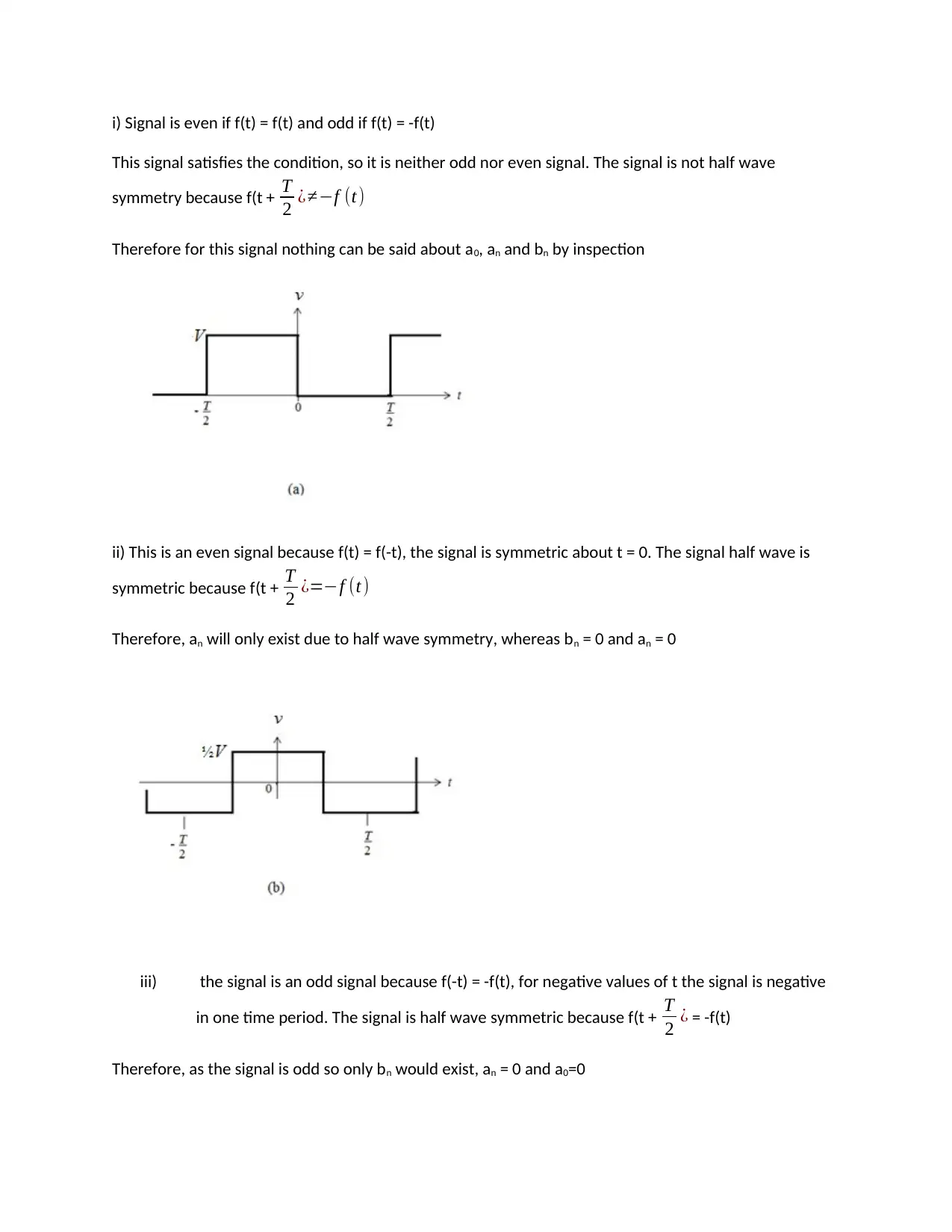
i) Signal is even if f(t) = f(t) and odd if f(t) = -f(t)
This signal satisfies the condition, so it is neither odd nor even signal. The signal is not half wave
symmetry because f(t + T
2 ¿≠−f (t)
Therefore for this signal nothing can be said about a0, an and bn by inspection
ii) This is an even signal because f(t) = f(-t), the signal is symmetric about t = 0. The signal half wave is
symmetric because f(t + T
2 ¿=−f (t)
Therefore, an will only exist due to half wave symmetry, whereas bn = 0 and an = 0
iii) the signal is an odd signal because f(-t) = -f(t), for negative values of t the signal is negative
in one time period. The signal is half wave symmetric because f(t + T
2 ¿ = -f(t)
Therefore, as the signal is odd so only bn would exist, an = 0 and a0=0
⊘ This is a preview!⊘
Do you want full access?
Subscribe today to unlock all pages.

Trusted by 1+ million students worldwide
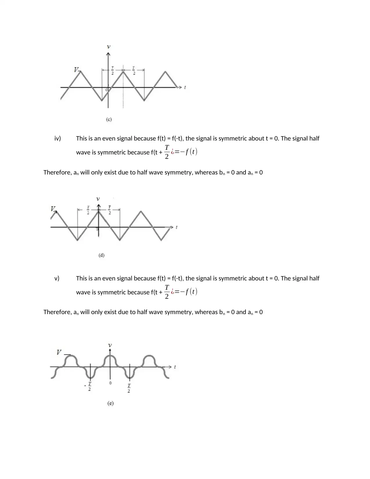
iv) This is an even signal because f(t) = f(-t), the signal is symmetric about t = 0. The signal half
wave is symmetric because f(t + T
2 ¿=−f (t)
Therefore, an will only exist due to half wave symmetry, whereas bn = 0 and an = 0
v) This is an even signal because f(t) = f(-t), the signal is symmetric about t = 0. The signal half
wave is symmetric because f(t + T
2 ¿=−f (t)
Therefore, an will only exist due to half wave symmetry, whereas bn = 0 and an = 0
wave is symmetric because f(t + T
2 ¿=−f (t)
Therefore, an will only exist due to half wave symmetry, whereas bn = 0 and an = 0
v) This is an even signal because f(t) = f(-t), the signal is symmetric about t = 0. The signal half
wave is symmetric because f(t + T
2 ¿=−f (t)
Therefore, an will only exist due to half wave symmetry, whereas bn = 0 and an = 0
Paraphrase This Document
Need a fresh take? Get an instant paraphrase of this document with our AI Paraphraser
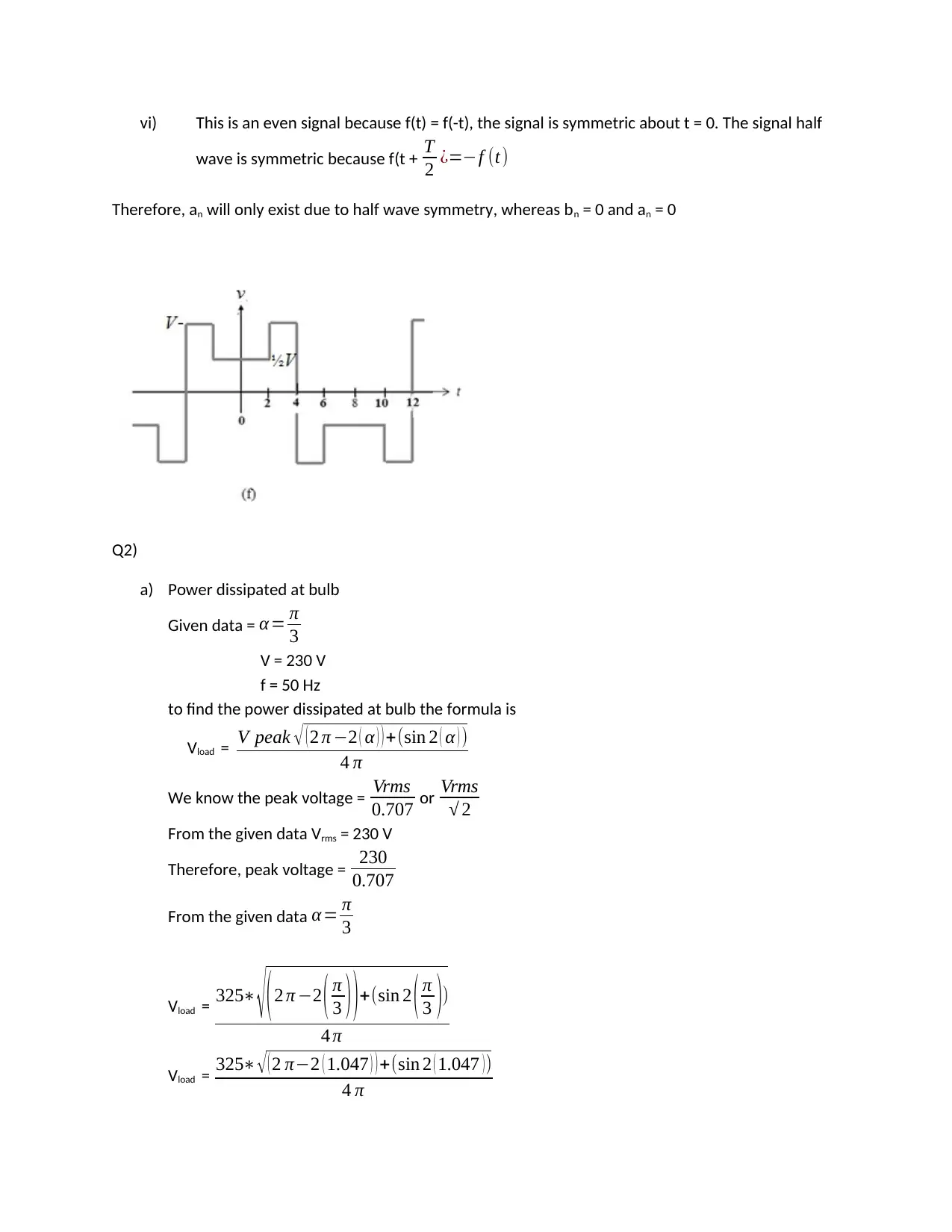
vi) This is an even signal because f(t) = f(-t), the signal is symmetric about t = 0. The signal half
wave is symmetric because f(t + T
2 ¿=−f (t)
Therefore, an will only exist due to half wave symmetry, whereas bn = 0 and an = 0
Q2)
a) Power dissipated at bulb
Given data = α = π
3
V = 230 V
f = 50 Hz
to find the power dissipated at bulb the formula is
Vload = V peak √ ( 2 π −2 ( α ) ) +(sin 2 ( α ) )
4 π
We know the peak voltage = Vrms
0.707 or Vrms
√ 2
From the given data Vrms = 230 V
Therefore, peak voltage = 230
0.707
From the given data α = π
3
Vload = 325∗ √( 2 π −2 ( π
3 ) ) +(sin 2 ( π
3 ))
4 π
Vload = 325∗ √ ( 2 π−2 ( 1.047 ) ) +(sin 2 ( 1.047 ) )
4 π
Vload = 325∗ √ ( 2 π− ( 2.094 ) ) +(sin ( 2.094 ) )
4 π
Vpeak = 325∗ √4.189+0.036
4 π
Vpeak = 325∗2.0554
4 π
= 668.031
4 π
Vpeak =53.160 V
Current is given as
I = power disipated∈bulb
Vrms
= 100
230
I = 0.43 A
Power dissipated = Vload * current
= 53.160 * 0.43
Power dissipated = 22.86 W
b)
The given shows a symmetrical wave form at the rectifier
The above figure is a symmetrical value form due to the wave form positive cycle and negative
are not same
This is due to the firing triggering pulse in start cycle of each positive as negative cycle
The circuit contain harmonic shown in the above due to asymmetrical wave form the circuit
The harmonic can affect the entire circuit.
4 π
Vpeak = 325∗ √4.189+0.036
4 π
Vpeak = 325∗2.0554
4 π
= 668.031
4 π
Vpeak =53.160 V
Current is given as
I = power disipated∈bulb
Vrms
= 100
230
I = 0.43 A
Power dissipated = Vload * current
= 53.160 * 0.43
Power dissipated = 22.86 W
b)
The given shows a symmetrical wave form at the rectifier
The above figure is a symmetrical value form due to the wave form positive cycle and negative
are not same
This is due to the firing triggering pulse in start cycle of each positive as negative cycle
The circuit contain harmonic shown in the above due to asymmetrical wave form the circuit
The harmonic can affect the entire circuit.
⊘ This is a preview!⊘
Do you want full access?
Subscribe today to unlock all pages.

Trusted by 1+ million students worldwide
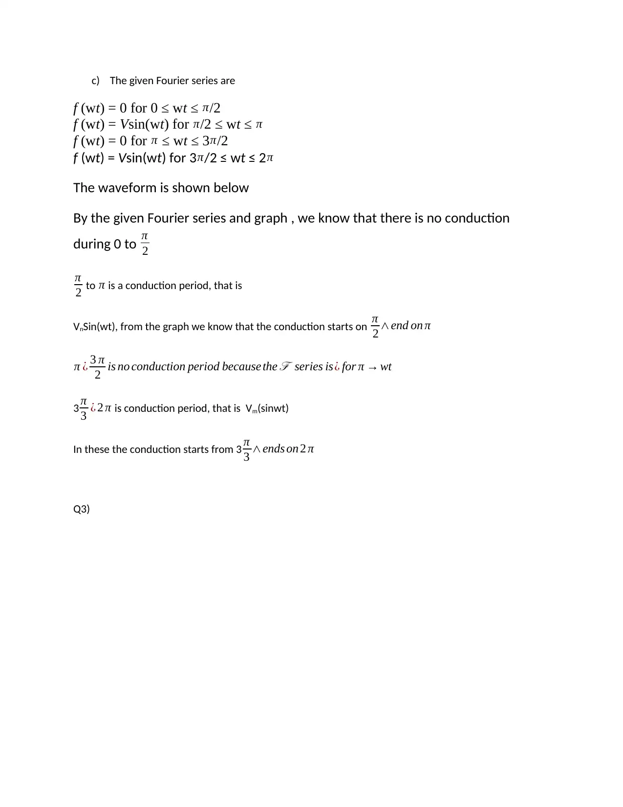
c) The given Fourier series are
f (wt) = 0 for 0 ≤ wt ≤ π/2
f (wt) = Vsin(wt) for π/2 ≤ wt ≤ π
f (wt) = 0 for π ≤ wt ≤ 3π/2
f (wt) = Vsin(wt) for 3 π/2 ≤ wt ≤ 2π
The waveform is shown below
By the given Fourier series and graph , we know that there is no conduction
during 0 to π
2
π
2 to π is a conduction period, that is
VnSin(wt), from the graph we know that the conduction starts on π
2 ∧end on π
π ¿ 3 π
2 is no conduction period because the ℱ series is¿ for π → wt
3 π
3 ¿ 2 π is conduction period, that is Vm(sinwt)
In these the conduction starts from 3 π
3 ∧ends on 2 π
Q3)
Paraphrase This Document
Need a fresh take? Get an instant paraphrase of this document with our AI Paraphraser
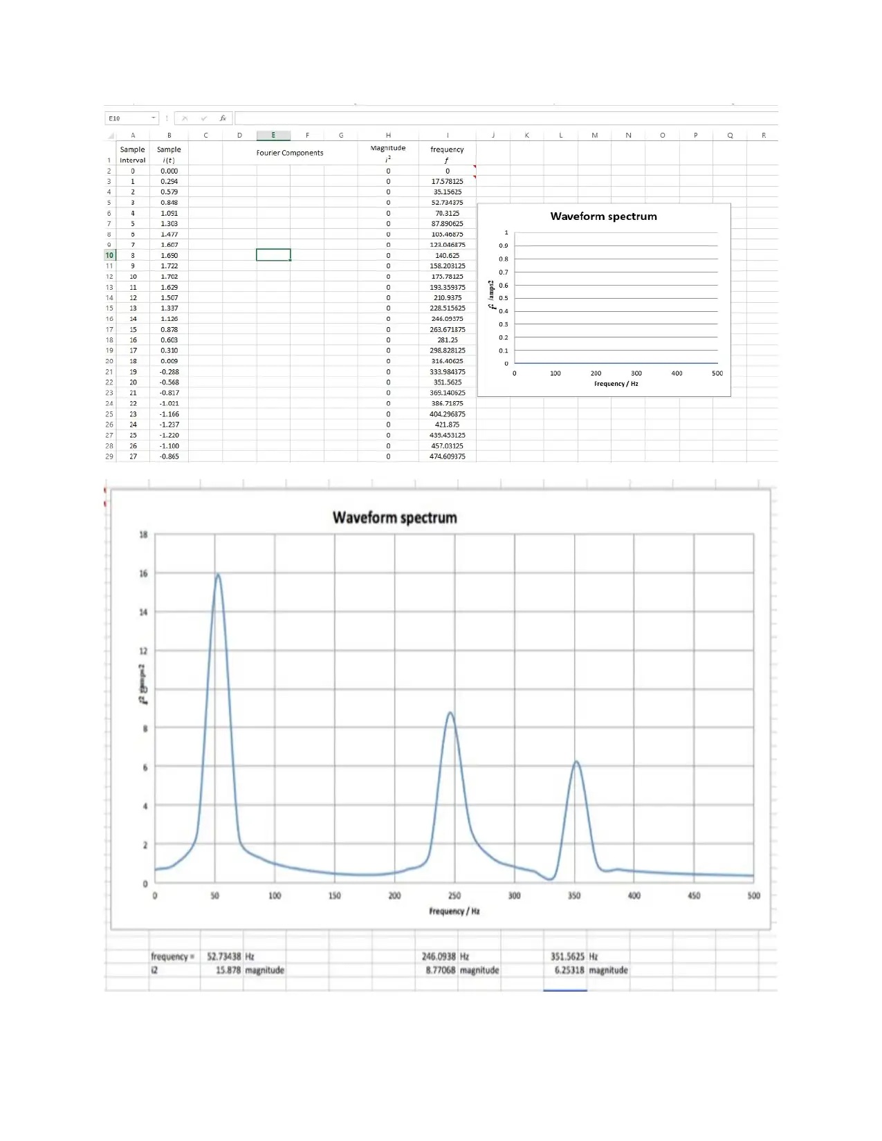
(c )The Total harmonic distortion
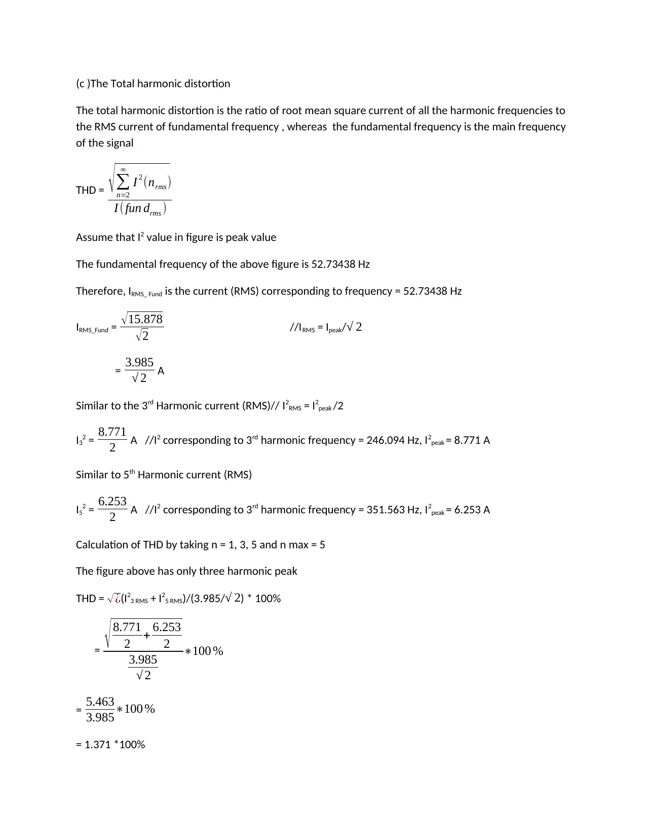
The total harmonic distortion is the ratio of root mean square current of all the harmonic frequencies to
the RMS current of fundamental frequency , whereas the fundamental frequency is the main frequency
of the signal
THD = √ ∑
n=2
∞
I 2 (nrms)
I (fun drms )
Assume that I2 value in figure is peak value
The fundamental frequency of the above figure is 52.73438 Hz
Therefore, IRMS_ Fund is the current (RMS) corresponding to frequency = 52.73438 Hz
IRMS_Fund = √ 15.878
√ 2 //IRMS = Ipeak/√ 2
= 3.985
√ 2 A
Similar to the 3rd Harmonic current (RMS)// I2RMS = I2peak /2
I32 = 8.771
2 A //I2 corresponding to 3rd harmonic frequency = 246.094 Hz, I2peak = 8.771 A
Similar to 5th Harmonic current (RMS)
I52 = 6.253
2 A //I2 corresponding to 3rd harmonic frequency = 351.563 Hz, I2peak = 6.253 A
Calculation of THD by taking n = 1, 3, 5 and n max = 5
The figure above has only three harmonic peak
THD = √ ¿(I23 RMS + I25 RMS)/(3.985/√ 2) * 100%
= √ 8.771
2 + 6.253
2
3.985
√ 2
∗100 %
= 5.463
3.985∗100 %
= 1.371 *100%
⊘ This is a preview!⊘
Do you want full access?
Subscribe today to unlock all pages.

Trusted by 1+ million students worldwide
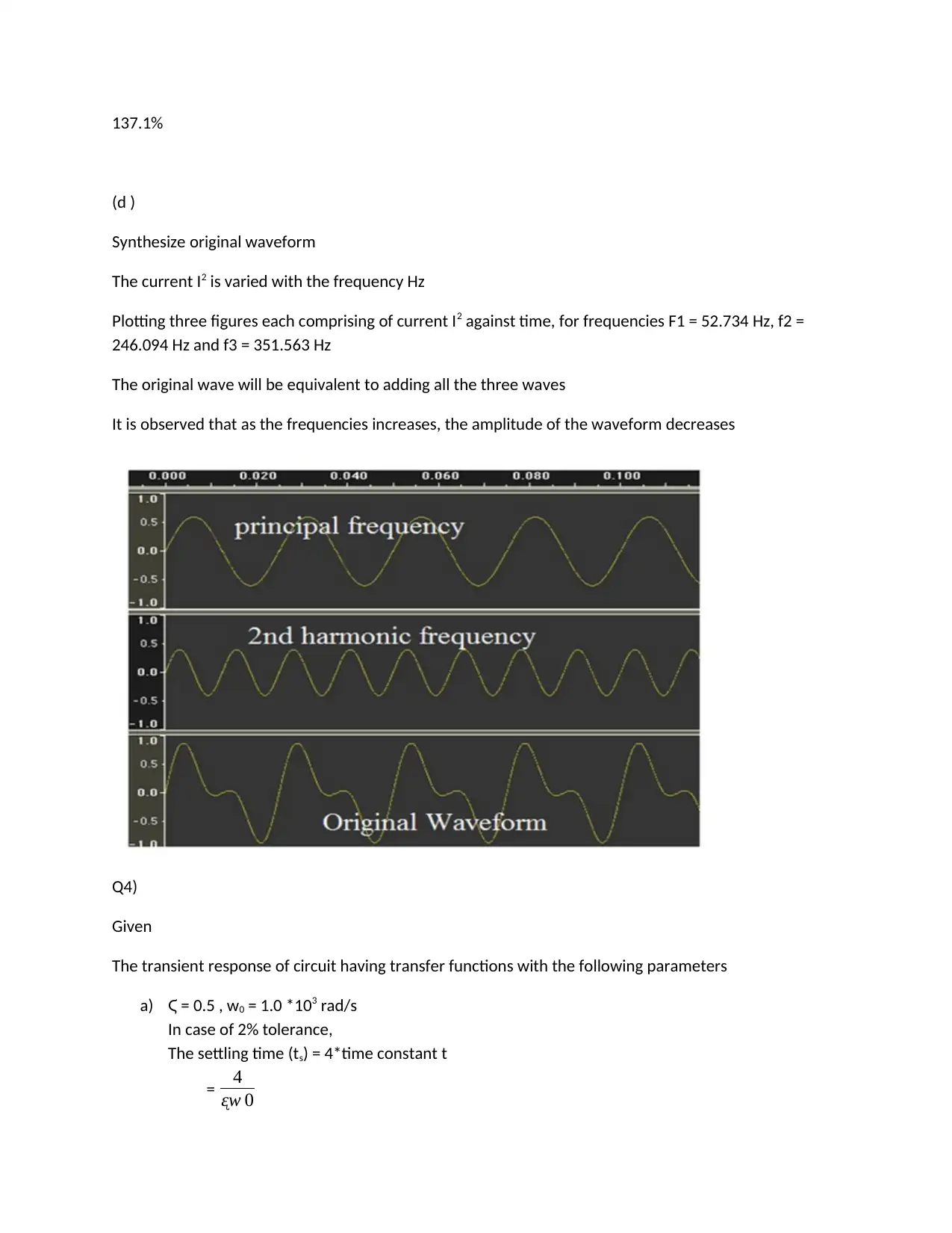
137.1%
(d )
Synthesize original waveform
The current I2 is varied with the frequency Hz
Plotting three figures each comprising of current I2 against time, for frequencies F1 = 52.734 Hz, f2 =
246.094 Hz and f3 = 351.563 Hz
The original wave will be equivalent to adding all the three waves
It is observed that as the frequencies increases, the amplitude of the waveform decreases
Q4)
Given
The transient response of circuit having transfer functions with the following parameters
a) Ϛ = 0.5 , w0 = 1.0 *103 rad/s
In case of 2% tolerance,
The settling time (ts) = 4*time constant t
= 4
ᶓw 0
Paraphrase This Document
Need a fresh take? Get an instant paraphrase of this document with our AI Paraphraser
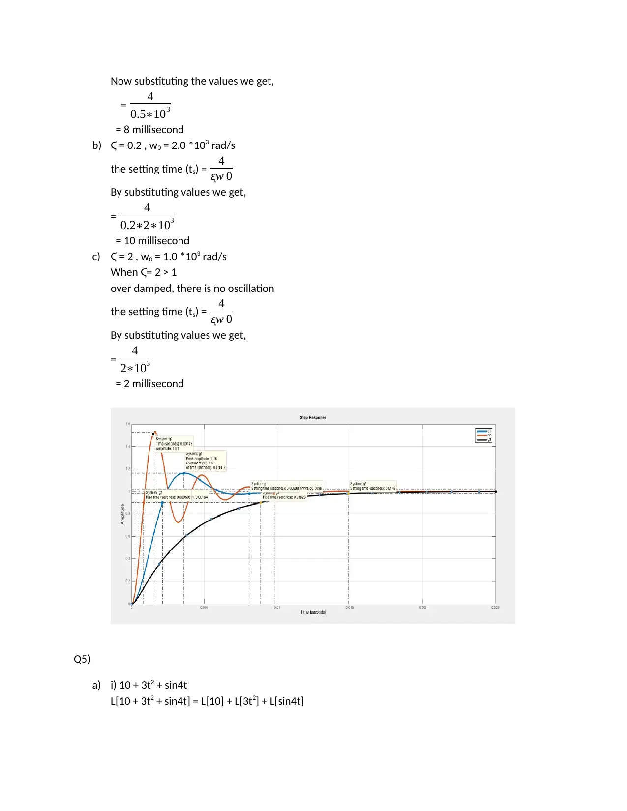
Now substituting the values we get,
= 4
0.5∗103
= 8 millisecond
b) Ϛ = 0.2 , w0 = 2.0 *103 rad/s
the setting time (ts) = 4
ᶓw 0
By substituting values we get,
= 4
0.2∗2∗103
= 10 millisecond
c) Ϛ = 2 , w0 = 1.0 *103 rad/s
When Ϛ= 2 > 1
over damped, there is no oscillation
the setting time (ts) = 4
ᶓw 0
By substituting values we get,
= 4
2∗103
= 2 millisecond
Q5)
a) i) 10 + 3t2 + sin4t
L[10 + 3t2 + sin4t] = L[10] + L[3t2] + L[sin4t]
= 4
0.5∗103
= 8 millisecond
b) Ϛ = 0.2 , w0 = 2.0 *103 rad/s
the setting time (ts) = 4
ᶓw 0
By substituting values we get,
= 4
0.2∗2∗103
= 10 millisecond
c) Ϛ = 2 , w0 = 1.0 *103 rad/s
When Ϛ= 2 > 1
over damped, there is no oscillation
the setting time (ts) = 4
ᶓw 0
By substituting values we get,
= 4
2∗103
= 2 millisecond
Q5)
a) i) 10 + 3t2 + sin4t
L[10 + 3t2 + sin4t] = L[10] + L[3t2] + L[sin4t]
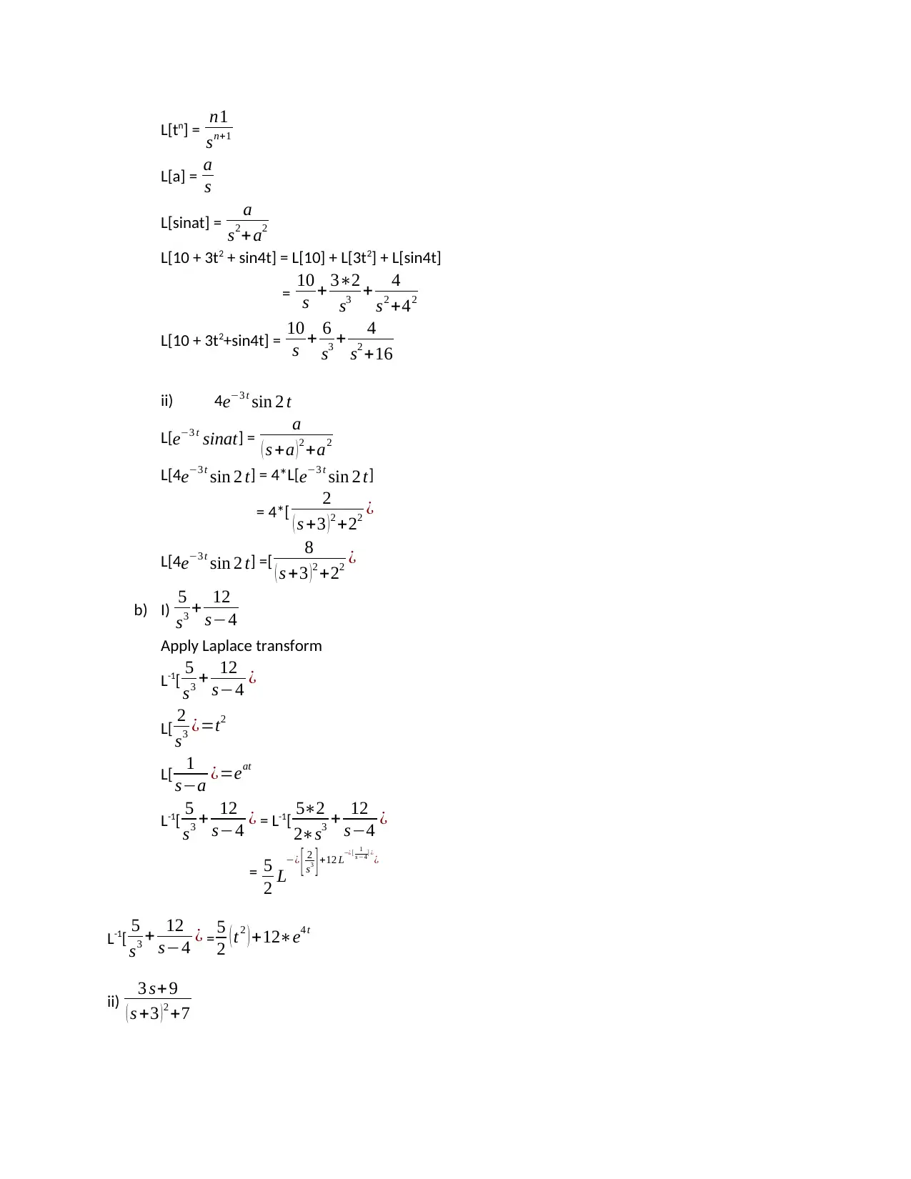
L[tn] = n1
sn+1
L[a] = a
s
L[sinat] = a
s2+ a2
L[10 + 3t2 + sin4t] = L[10] + L[3t2] + L[sin4t]
= 10
s + 3∗2
s3 + 4
s2 +42
L[10 + 3t2+sin4t] = 10
s + 6
s3 + 4
s2 +16
ii) 4e−3 t sin 2 t
L[e−3 t sinat] = a
( s +a ) 2 +a2
L[4e−3 t sin 2 t] = 4*L[e−3 t sin 2 t]
= 4*[ 2
( s +3 ) 2 +22 ¿
L[4e−3 t sin 2 t] =[ 8
( s +3 )2 +22 ¿
b) I) 5
s3 + 12
s−4
Apply Laplace transform
L-1[ 5
s3 + 12
s−4 ¿
L[ 2
s3 ¿=t2
L[ 1
s−a ¿=eat
L-1[ 5
s3 + 12
s−4 ¿ = L-1[ 5∗2
2∗s3 + 12
s−4 ¿
= 5
2 L
−¿ [ 2
s3 ] +12 L−¿[ 1
s −4] ¿
¿
L-1[ 5
s3 + 12
s−4 ¿ = 5
2 ( t2 ) +12∗e4 t
ii) 3 s+ 9
( s +3 ) 2 +7
⊘ This is a preview!⊘
Do you want full access?
Subscribe today to unlock all pages.

Trusted by 1+ million students worldwide
1 out of 14
Related Documents
Your All-in-One AI-Powered Toolkit for Academic Success.
+13062052269
info@desklib.com
Available 24*7 on WhatsApp / Email
![[object Object]](/_next/static/media/star-bottom.7253800d.svg)
Unlock your academic potential
Copyright © 2020–2026 A2Z Services. All Rights Reserved. Developed and managed by ZUCOL.


