FEA Based Modelling & Analysis of Composite Leaf Spring under Load
VerifiedAdded on 2023/06/04
|4
|2858
|216
Report
AI Summary
This report details the modeling and analysis of a composite leaf spring (GFRP) under static load conditions using Pro-E and ANSYS software, comparing its performance to a conventional steel leaf spring (60Si7). The study involves creating a virtual model of the composite leaf spring in Pro-E, simulating it in ANSYS, and comparing the results based on stress and deflection. Experimental procedures for testing a conventional steel leaf spring are described, and material properties for both steel and E-Glass/Epoxy are provided. The report includes comparative analysis of load and deflection, along with finite element analysis results, highlighting the advantages of composite leaf springs in terms of weight reduction and deflection characteristics. The conclusion emphasizes the differences in stress and deflection between steel and composite leaf springs under the same loading conditions.
“Modelling and Analysis of Composite Leaf Spring under the Static Load Condition by using FEA”
International Journal of Mechanical & Industrial Engineering, Volume 1 Issue 1-2011
1
“Modelling and Analysis of Composite Leaf Spring under the
Static Load Condition by using FEA”
M. M. Patunkar1, D. R. Dolas2
1IInd year M.E.(Mfg. Engg.) Mech. Engg. Dept., 2 Assistant Professor, Mech. Engg. Dept.,
MGM’s Jawaharlal Nehru Engineering College, Aurangabad, Maharashtra – 431003, India.
E-mail :mpatunkar@gmail.com, drdolas@indiatimes.com
Abstract - Leaf springs are one of the oldest suspension components
they are still frequently used, especially in commercial vehicles. The
past literature survey shows that leaf springs are designed as
generalized force elements where the position, velocity and orientation
of the axle mounting gives the reaction forces in the chassis attachment
positions. Another part has to be focused, is the automobile industry
has shown increased interest in the replacement of steel spring with
composite leaf spring due to high strength to weight ratio. Therefore,
analysis of the composite material becomes equally important to study
the behavior of Composite Leaf Spring. The objective of this paper is to
present modeling and analysis of composite mono leaf spring (GFRP)
and compare its results. Modelling is done using Pro-E (Wild Fire) 5.0
and Analysis is carried out by using ANSYS 10.0 software for better
understanding.
Keywords - Composite Leaf Springs, Glass Fiber Reinforced
Plastic (GFRP), Static load condition.
I. I. INTRODUCTION
Increasing competition and innovations in automobile
sector tends to modify the existing products or replacing
old products by new and advanced material products. A
suspension system of vehicle is also an area where these
innovations are carried out regularly. More efforts are
taken in order to increase the comfort of user. Appropriate
balance of comfort riding qualities and economy in
manufacturing of leaf spring becomes an obvious
necessity. To improve the suspension system many
modification have taken place over the time. Inventions of
parabolic leaf spring, use of composite materials for these
springs are some of these latest modifications in
suspension systems. This paper is mainly focused on the
implementation of composite materials by replacing steel
in conventional leaf springs of a suspension system.
Automobile-sector is showing an increased interest in the
area of composite material-leaf springs due to their high
strength to weight ratio. Therefore analysis of composite
material leaf springs has become essential in showing the
comparative results with conventional leaf springs.
Advantages of leaf spring over helical spring are that
the ends of the springs are guided along a definite path so
as to act as a structural member in addition to shock
absorbing device. This is the reason why leaf springs are
still used widely in a variety of automobiles to carry axial
loads, lateral loads and brake-torque in the suspension
system.
In this analysis the conventional steel leaf spring is
tested for static load condition and results are compared
with a virtual model of composite material leaf spring.
Leaf spring is modeled in Pro-E 5.0 CAD software and it
is imported and simulated in ANSYS 10.0 for better
understanding. Results of Composite Leaf Spring are
compared on the basis of analysis reports produced by
ANSYS software. The material used for conventional steel
leaf spring is 60Si7 (BIS) and for composite leaf spring E
- Glass/Epoxy material is used.
II. LITERATURE SURVEY
Many industrial visits, past recorded data shows that
steel leaf springs are manufactured by EN45, EN45A,
60Si7, EN47, 50Cr4V2, 55SiCr7 and 50CrMoCV4 etc.
These materials are widely used for production of the
parabolic leaf springs and conventional multi leaf springs.
Leaf springs absorb the vehicle vibrations, shocks and
bump loads (Induced due to road irregularities) by means
of spring deflections, so that the potential energy is stored
in the leaf spring and then relieved slowly [1]. Ability to
store and absorb more amount of strain energy ensures the
comfortable suspension system.
Many suspension systems work on the same principle
including conventional leaf springs. However, for the
same load and shock absorbing performance, conventional
(steel) leaf springs use excess of material making them
considerably heavy. This can be improved by introducing
composite materials in place of steel in the conventional
spring. Studies and researches were carried out on the
applications of the composite materials in leaf spring [1,2].
A composite mono leaf spring with an integral eye was
manufactured and tested for the static load conditions [2].
Fatigue life prediction was also done by authors so as to
ensure a reliable number of life cycles of a leaf spring.
Further, a leaf spring had been modeled in conventional
way and simulated for the kinematic and dynamic
comparatives [3]. Cyclic creep and cyclic deformation was
also studied [4]. Efforts were taken for Finite Element
Analysis of multi leaf springs. These springs were
simulated and analyzed by using ANSYS 7.1[5].
Premature failure in leaf springs was also studied so as to
suggest remedies on application of composite leaf springs.
[6, 7, 8]
Paraphrase This Document
Need a fresh take? Get an instant paraphrase of this document with our AI Paraphraser
“Modelling and Analysis of Composite Leaf Spring under the Static Load Condition by using FEA”
International Journal of Mechanical & Industrial Engineering, Volume 1 Issue 1-2011
2
III. EXPERIMENTAL PROCEDURE
In this paper, a comparative analysis of conventional
steel leaf spring is done with a virtual model of a
composite leaf spring under static load condition only.
Conventional leaf spring is first tested under static load
condition by using Hydraulic Static Load Test Rig.
Mounting of the leaf spring is done by keeping it in
inverted manner on the test bed. Two eye ends are held in
the clamping devices and load is applied from the top, at
the center of leaf spring. The spring is loaded from zero to
maximum load (i.e. 25 Kg) and again back to zero. The
vertical deflection of the spring is recorded in the load
interval of 5 Kg and specified as per the SOP prescribed
by SAE. To measure the load dial indicator is used which
is located beside the Test Rig and deflection is measured
by strain gauges located at the clamping of the test rig.
IV. SPECIFICATION OF THE CONVENTIONAL
LEAF SPRING
The test steel leaf spring used for experiment is made
up of 60Si7. The composition of material is 0.56 C%, 1.80
SI%, 0.70 Mn%, 0.045 P%, 0.045 S%. Following are the
parameters for the 60Si7.
Table No.1 Specification of Existing Leaf Spring
The leaf spring is used in the TATA SUMO vehicle,
for Rear Suspension. Before testing of the leaf spring Shot
Peening is done on all leaves.
V. SELECTION OF COMPOSITE MATERIAL
As mentioned earlier, the ability to absorb and store
more amount of energy ensures the comfortable operation
of a suspension system. However, the problem of heavy
weight of spring is still persistent. This can be remedied
by introducing composite material, in place of steel in the
conventional leaf spring. Research has indicated that the
results of E-Glass/Epoxy were found with good
characteristics for storing strain energy [1]. So, a virtual
model of leaf spring was created in Pro-E. Model is
imported in ANSYS and then material is assigned to the
model. These results can be used for comparison with the
conventional steel leaf spring.
VI. MATERIAL PROPERTIES OF
VII. E-GLASS/ EPOXY
Table No.2 Properties of E-Glass/Epoxy material
Sr.
No
Properties Value
1 Tensile modulus along X-direction
(Ex), MPa 34000
2 Tensile modulus along Y-direction
(Ey), MPa 6530
3 Tensile modulus along Z-direction
(Ez), MPa 6530
4 Tensile strength of the material,
MPa 900
5 Compressive strength of the
material, MPa 450
6 Shear modulus along XY-direction
(Gxy), MPa 2433
7 Shear modulus along YZ-direction
(Gyz), MPa 1698
8 Shear modulus along ZX-direction
(Gzx), MPa 2433
9 Poisson ratio along XY-direction
(NUxy) 0.217
10 Poisson ratio along YZ-direction
(NUyz) 0.366
11 Poisson ratio along ZX-direction
(NUzx) 0.217
12 Mass density of the material (ρ),
Kg/mm3 2.6x10³
13 Flexural modulus of the material,
MPa 40000
14 Flexural strength of the material,
MPa 1200
VIII. COMPARATIVE ANALYSIS OF LOAD AND
DEFELECTION OF THE STEEL AND COMPOSITE
LEAF SPRINGS
Table No.3 Comparative Analysis of Steel Leaf and
Virtual Model of Composite Leaf Spring
Conventional
Steel leaf spring
Virtual model of
Composite Leaf
Spring (FEA)
Sr.
No
.
Load
(Kg)
Deflectio
n (mm)
Stress
(Kgf/mm2
)
Deflectio
n (mm)
Stress
(Kgf/mm2)
1 5 31.127 17.81
8 24.23 59.102
Parameters Value
Total Length of the spring
(Eye to Eye) 1540 mm
Free Camber (At no load condition) 136 mm
No. of full length leave
(Master Leaf) 01
Thickness of leaf 13 mm
Width of leaf spring 70 mm
Maxm Load given on spring 25 Kg
Young’s Modulus of the spring 22426.09 Kgf/mm2
Weight of the leaf spring 23 Kg
“Modelling and Analysis of Composite Leaf Spring under the Static Load Condition by using FEA”
International Journal of Mechanical & Industrial Engineering, Volume 1 Issue 1-2011
3
2 10 62.253 35.63
7 48.461 118.20
4
3 15 93.38 53.45
5 72.691 177.30
7
4 20 124.506 71.27
3 96.922 236.40
9
5 22.5 140.069 80.18
2 109.037 265.96
6 25 155.633 89.09
1 121.152 295.51
1
IX. COMPARATIVE ANALYSIS OF LOAD AND
DEFELECTION OF THE STEEL AND COMPOSITE
LEAF SPRINGS
Table No.3 Overall Comparative Analysis of springs
Sr.
No
Paramete
r
Expt.
result
Analytic
al Result
FEA
(ANSYS
10.0)
1 Load
(Kg) 25 25 25
2
Max.
Stress
(Kgf/mm
2)
92 89.091 295.511
3
Max.
Deflectio
n (mm)
160 155.633 121.152
4
Max.
Stiffness
(Kg/mm)
0.156 0.1606 0.20
5 Weight
(Kg) 23 --- 3.59
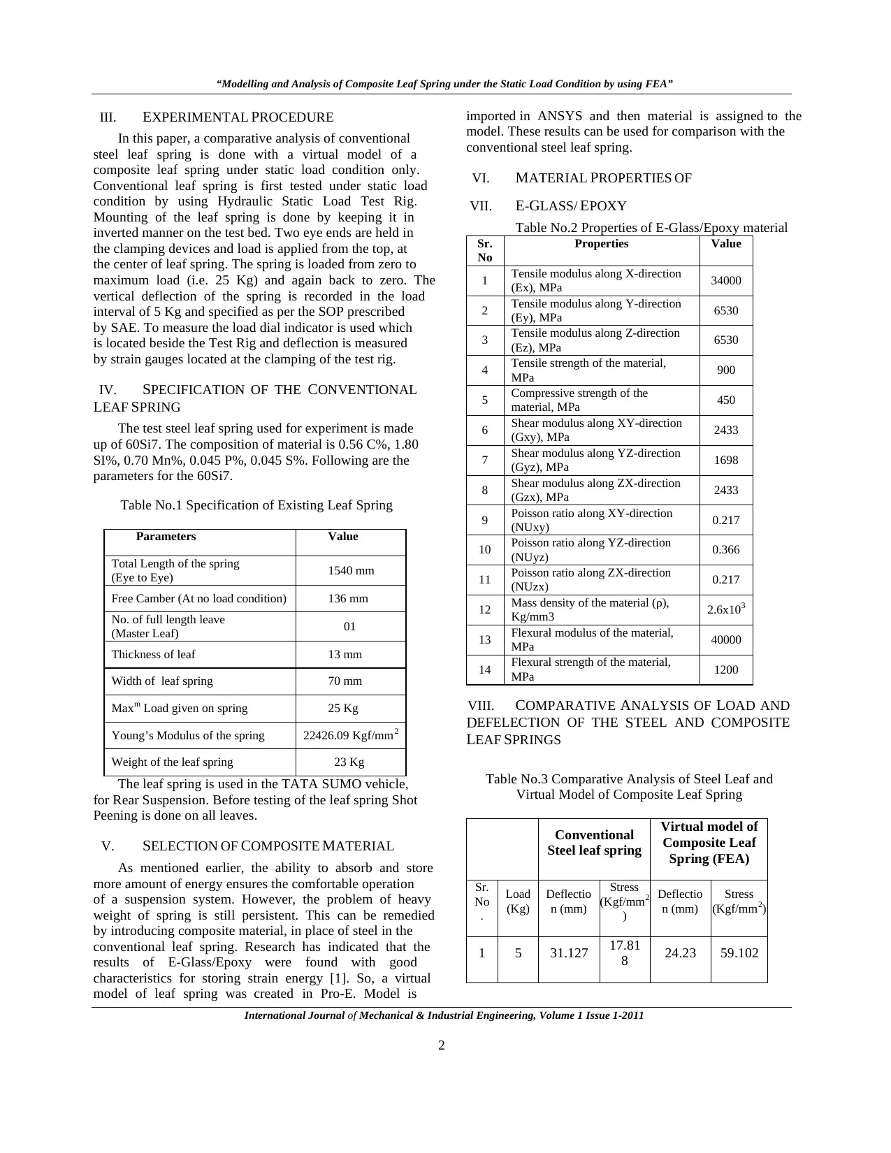
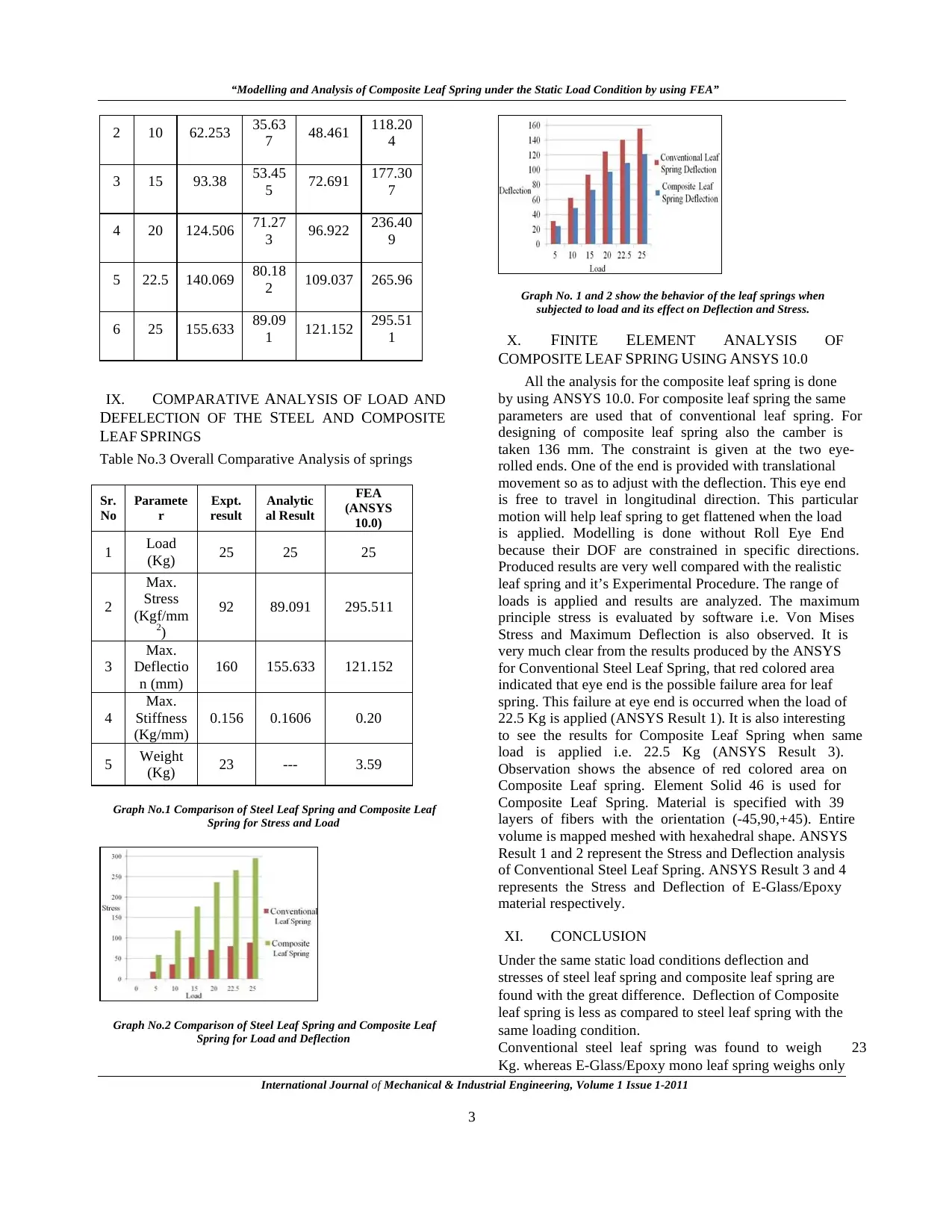
Graph No.1 Comparison of Steel Leaf Spring and Composite Leaf
Spring for Stress and Load
Graph No.2 Comparison of Steel Leaf Spring and Composite Leaf
Spring for Load and Deflection
Graph No. 1 and 2 show the behavior of the leaf springs when
subjected to load and its effect on Deflection and Stress.
X. FINITE ELEMENT ANALYSIS OF
COMPOSITE LEAF SPRING USING ANSYS 10.0
All the analysis for the composite leaf spring is done
by using ANSYS 10.0. For composite leaf spring the same
parameters are used that of conventional leaf spring. For
designing of composite leaf spring also the camber is
taken 136 mm. The constraint is given at the two eye-
rolled ends. One of the end is provided with translational
movement so as to adjust with the deflection. This eye end
is free to travel in longitudinal direction. This particular
motion will help leaf spring to get flattened when the load
is applied. Modelling is done without Roll Eye End
because their DOF are constrained in specific directions.
Produced results are very well compared with the realistic
leaf spring and it’s Experimental Procedure. The range of
loads is applied and results are analyzed. The maximum
principle stress is evaluated by software i.e. Von Mises
Stress and Maximum Deflection is also observed. It is
very much clear from the results produced by the ANSYS
for Conventional Steel Leaf Spring, that red colored area
indicated that eye end is the possible failure area for leaf
spring. This failure at eye end is occurred when the load of
22.5 Kg is applied (ANSYS Result 1). It is also interesting
to see the results for Composite Leaf Spring when same
load is applied i.e. 22.5 Kg (ANSYS Result 3).
Observation shows the absence of red colored area on
Composite Leaf spring. Element Solid 46 is used for
Composite Leaf Spring. Material is specified with 39
layers of fibers with the orientation (-45,90,+45). Entire
volume is mapped meshed with hexahedral shape. ANSYS
Result 1 and 2 represent the Stress and Deflection analysis
of Conventional Steel Leaf Spring. ANSYS Result 3 and 4
represents the Stress and Deflection of E-Glass/Epoxy
material respectively.
XI. CONCLUSION
Under the same static load conditions deflection and
stresses of steel leaf spring and composite leaf spring are
found with the great difference. Deflection of Composite
leaf spring is less as compared to steel leaf spring with the
same loading condition.
Conventional steel leaf spring was found to weigh 23
Kg. whereas E-Glass/Epoxy mono leaf spring weighs only
International Journal of Mechanical & Industrial Engineering, Volume 1 Issue 1-2011
3
2 10 62.253 35.63
7 48.461 118.20
4
3 15 93.38 53.45
5 72.691 177.30
7
4 20 124.506 71.27
3 96.922 236.40
9
5 22.5 140.069 80.18
2 109.037 265.96
6 25 155.633 89.09
1 121.152 295.51
1
IX. COMPARATIVE ANALYSIS OF LOAD AND
DEFELECTION OF THE STEEL AND COMPOSITE
LEAF SPRINGS
Table No.3 Overall Comparative Analysis of springs
Sr.
No
Paramete
r
Expt.
result
Analytic
al Result
FEA
(ANSYS
10.0)
1 Load
(Kg) 25 25 25
2
Max.
Stress
(Kgf/mm
2)
92 89.091 295.511
3
Max.
Deflectio
n (mm)
160 155.633 121.152
4
Max.
Stiffness
(Kg/mm)
0.156 0.1606 0.20
5 Weight
(Kg) 23 --- 3.59
Graph No.1 Comparison of Steel Leaf Spring and Composite Leaf
Spring for Stress and Load
Graph No.2 Comparison of Steel Leaf Spring and Composite Leaf
Spring for Load and Deflection
Graph No. 1 and 2 show the behavior of the leaf springs when
subjected to load and its effect on Deflection and Stress.
X. FINITE ELEMENT ANALYSIS OF
COMPOSITE LEAF SPRING USING ANSYS 10.0
All the analysis for the composite leaf spring is done
by using ANSYS 10.0. For composite leaf spring the same
parameters are used that of conventional leaf spring. For
designing of composite leaf spring also the camber is
taken 136 mm. The constraint is given at the two eye-
rolled ends. One of the end is provided with translational
movement so as to adjust with the deflection. This eye end
is free to travel in longitudinal direction. This particular
motion will help leaf spring to get flattened when the load
is applied. Modelling is done without Roll Eye End
because their DOF are constrained in specific directions.
Produced results are very well compared with the realistic
leaf spring and it’s Experimental Procedure. The range of
loads is applied and results are analyzed. The maximum
principle stress is evaluated by software i.e. Von Mises
Stress and Maximum Deflection is also observed. It is
very much clear from the results produced by the ANSYS
for Conventional Steel Leaf Spring, that red colored area
indicated that eye end is the possible failure area for leaf
spring. This failure at eye end is occurred when the load of
22.5 Kg is applied (ANSYS Result 1). It is also interesting
to see the results for Composite Leaf Spring when same
load is applied i.e. 22.5 Kg (ANSYS Result 3).
Observation shows the absence of red colored area on
Composite Leaf spring. Element Solid 46 is used for
Composite Leaf Spring. Material is specified with 39
layers of fibers with the orientation (-45,90,+45). Entire
volume is mapped meshed with hexahedral shape. ANSYS
Result 1 and 2 represent the Stress and Deflection analysis
of Conventional Steel Leaf Spring. ANSYS Result 3 and 4
represents the Stress and Deflection of E-Glass/Epoxy
material respectively.
XI. CONCLUSION
Under the same static load conditions deflection and
stresses of steel leaf spring and composite leaf spring are
found with the great difference. Deflection of Composite
leaf spring is less as compared to steel leaf spring with the
same loading condition.
Conventional steel leaf spring was found to weigh 23
Kg. whereas E-Glass/Epoxy mono leaf spring weighs only
⊘ This is a preview!⊘
Do you want full access?
Subscribe today to unlock all pages.
Trusted by 1+ million students worldwide
“Modelling and Analysis of Composite Leaf Spring under the Static Load Condition by using FEA”
International Journal of Mechanical & Industrial Engineering, Volume 1 Issue 1-2011
4
3.59 Kg. Indicating reduction in weight by 84.40% same
level of performance.
Conventionl Leaf spring show failure at eye end only. At
maximum load condition also Composite Leaf Spring
shows the minimum deflection as compared to Steel Leaf
Spring.
Composite leaf spring can be used on smooth roads with
very high performance expectations.
However on rough road conditions due to lower chipping
resistance failure from chipping of composite leaf spring is
highly probable.
XII. ACKNOWLEDGEMENT
The authors would like to thank Prof. S. D.
Deshmukh, Principal, JNEC, Aurangabad for his valuable
guidance along with Mr. Harbaksh Singh of Ajanta Auto
Pvt., Ltd for significant information on leaf springs and
making available their test facility.
XIII. REFERENCES
[1] Senthil kumar and Vijayarangan, “Analytical and Experimental
studies on Fatigue life Prediction of steel leaf soringand
composite leaf multi leaf spring for Light passanger veicles using
life data analysis” ISSN 1392 1320 material science Vol. 13 No.2
2007.
[2] Shiva Shankar and Vijayarangan “Mono Composite Leaf Spring
for Light Weight Vehicle Design, End Joint, Analysis and
Testing” ISSN 1392 Material Science Vol. 12, No.3, 2006.
[3] Niklas Philipson and Modelan AB “Leaf spring modelling” ideon
Science Park SE-22370 Lund, Sweden
[4] Zhi’an Yang and et al “Cyclic Creep and Cyclic Deformation of
High-Strength Spring Steels and the Evaluation of the Sag
Effect:Part I. Cyclic Plastic Deformation Behavior” Material and
Material Transaction A Vol 32A, July 2001—1697
[5] Muhammad Ashiqur Rahman and et al “Inelastic deformations
of stainless steel leaf springs-experiment and nonlinear analysis”
Meccanica Springer Science Business Media B.V. 2009
[6] C.K. Clarke and G.E. Borowski “Evaluation of Leaf Spring
Failure” ASM International, Journal of Failure Analysis and
Prevention, Vol5 (6) Pg. No.(54-63)
[7] J.J. Fuentes and et al “Premature Fracture in Automobile Leaf
Springs” Journal of Science Direct, Engineering Failure
Analysis Vol. 16 (2009) Pg. No. 648-655.
[8] J.P. Hou and et al “Evolution Of The Eye End Design Of A
Composite Leaf Spring For Heavy Axle Load ” Journal of
Science Direct, Composite Structures 78(2007) Pg. No. (351-358)
[9] Practical Finite Element Analysis by Nitin S. Gokhale
[10] Composites – A Design Guide by Terry Richardson
[11] ANSYS 10.0 Help for FEA Analysis
[12] Text book of Machine Design by R.S. Khurmi and J.K. Gupta
[13] Introduction to Steel Reference Books S. N. Bagchi and Kuldeep
Prakash
[14] Spring Designers Hand Book by Carlson
[15] Properties of Engineering Materials by Higgins R. A
[16] Handbook of Design of Equipments by Abdulla and Shariff.
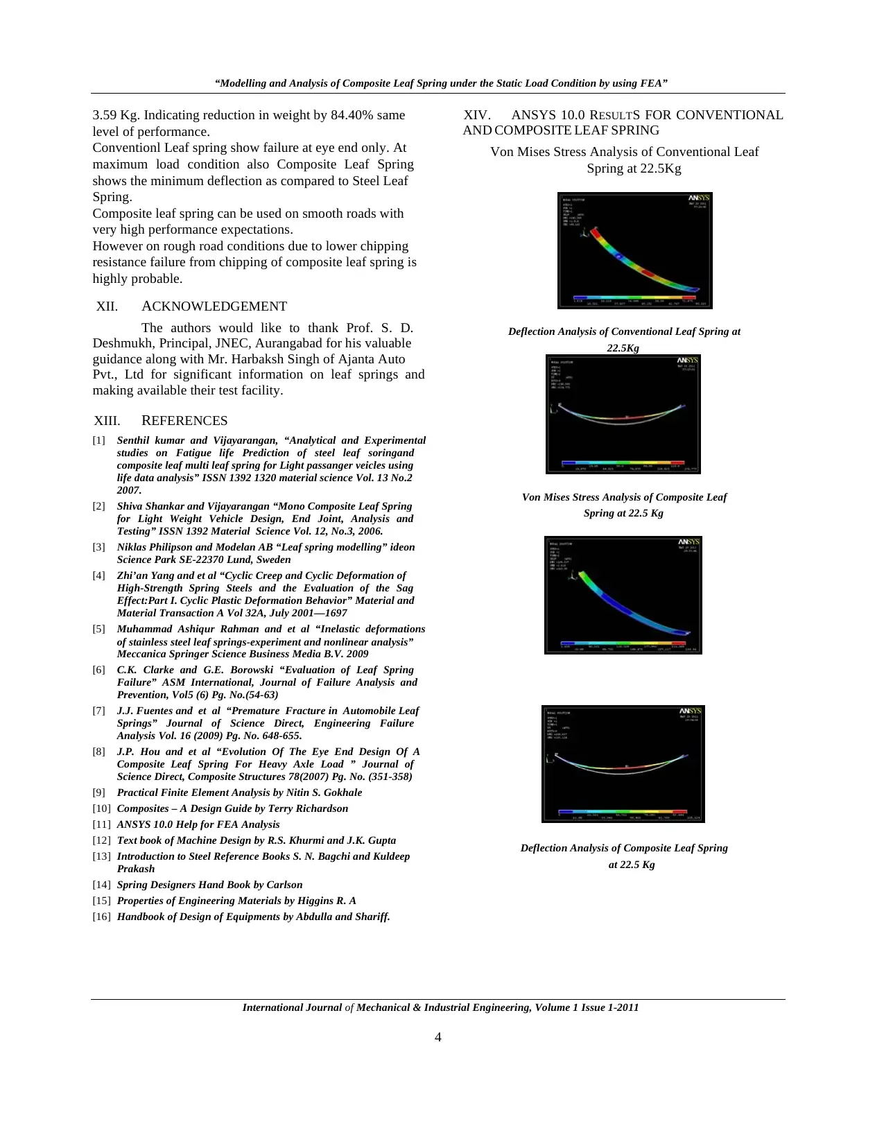
XIV. ANSYS 10.0 RESULTS FOR CONVENTIONAL
AND COMPOSITE LEAF SPRING
Von Mises Stress Analysis of Conventional Leaf
Spring at 22.5Kg
Deflection Analysis of Conventional Leaf Spring at
22.5Kg
Von Mises Stress Analysis of Composite Leaf
Spring at 22.5 Kg
Deflection Analysis of Composite Leaf Spring
at 22.5 Kg
International Journal of Mechanical & Industrial Engineering, Volume 1 Issue 1-2011
4
3.59 Kg. Indicating reduction in weight by 84.40% same
level of performance.
Conventionl Leaf spring show failure at eye end only. At
maximum load condition also Composite Leaf Spring
shows the minimum deflection as compared to Steel Leaf
Spring.
Composite leaf spring can be used on smooth roads with
very high performance expectations.
However on rough road conditions due to lower chipping
resistance failure from chipping of composite leaf spring is
highly probable.
XII. ACKNOWLEDGEMENT
The authors would like to thank Prof. S. D.
Deshmukh, Principal, JNEC, Aurangabad for his valuable
guidance along with Mr. Harbaksh Singh of Ajanta Auto
Pvt., Ltd for significant information on leaf springs and
making available their test facility.
XIII. REFERENCES
[1] Senthil kumar and Vijayarangan, “Analytical and Experimental
studies on Fatigue life Prediction of steel leaf soringand
composite leaf multi leaf spring for Light passanger veicles using
life data analysis” ISSN 1392 1320 material science Vol. 13 No.2
2007.
[2] Shiva Shankar and Vijayarangan “Mono Composite Leaf Spring
for Light Weight Vehicle Design, End Joint, Analysis and
Testing” ISSN 1392 Material Science Vol. 12, No.3, 2006.
[3] Niklas Philipson and Modelan AB “Leaf spring modelling” ideon
Science Park SE-22370 Lund, Sweden
[4] Zhi’an Yang and et al “Cyclic Creep and Cyclic Deformation of
High-Strength Spring Steels and the Evaluation of the Sag
Effect:Part I. Cyclic Plastic Deformation Behavior” Material and
Material Transaction A Vol 32A, July 2001—1697
[5] Muhammad Ashiqur Rahman and et al “Inelastic deformations
of stainless steel leaf springs-experiment and nonlinear analysis”
Meccanica Springer Science Business Media B.V. 2009
[6] C.K. Clarke and G.E. Borowski “Evaluation of Leaf Spring
Failure” ASM International, Journal of Failure Analysis and
Prevention, Vol5 (6) Pg. No.(54-63)
[7] J.J. Fuentes and et al “Premature Fracture in Automobile Leaf
Springs” Journal of Science Direct, Engineering Failure
Analysis Vol. 16 (2009) Pg. No. 648-655.
[8] J.P. Hou and et al “Evolution Of The Eye End Design Of A
Composite Leaf Spring For Heavy Axle Load ” Journal of
Science Direct, Composite Structures 78(2007) Pg. No. (351-358)
[9] Practical Finite Element Analysis by Nitin S. Gokhale
[10] Composites – A Design Guide by Terry Richardson
[11] ANSYS 10.0 Help for FEA Analysis
[12] Text book of Machine Design by R.S. Khurmi and J.K. Gupta
[13] Introduction to Steel Reference Books S. N. Bagchi and Kuldeep
Prakash
[14] Spring Designers Hand Book by Carlson
[15] Properties of Engineering Materials by Higgins R. A
[16] Handbook of Design of Equipments by Abdulla and Shariff.
XIV. ANSYS 10.0 RESULTS FOR CONVENTIONAL
AND COMPOSITE LEAF SPRING
Von Mises Stress Analysis of Conventional Leaf
Spring at 22.5Kg
Deflection Analysis of Conventional Leaf Spring at
22.5Kg
Von Mises Stress Analysis of Composite Leaf
Spring at 22.5 Kg
Deflection Analysis of Composite Leaf Spring
at 22.5 Kg
1 out of 4
Related Documents


Your All-in-One AI-Powered Toolkit for Academic Success.
+13062052269
info@desklib.com
Available 24*7 on WhatsApp / Email
![[object Object]](/_next/static/media/star-bottom.7253800d.svg)
Unlock your academic potential
Copyright © 2020–2026 A2Z Services. All Rights Reserved. Developed and managed by ZUCOL.