ProductsLogo
LogoStudy Documents
LogoAI Grader
LogoAI Answer
LogoAI Code Checker
LogoPlagiarism Checker
LogoAI Paraphraser
LogoAI Quiz
LogoAI Detector
PricingBlogAbout Us
logo

Computational Fluid Dynamics: Methodology, Setup, Solution and Results

Verified

Added on  2023/06/03

|9
|751
|447
AI Summary
This document provides an introduction to Computational Fluid Dynamics and its discrete solution. It covers the methodology, setup, solution and results of the simulation. The document also discusses the applications, advantages and disadvantages of Computational Fluid Dynamics.

Contribute Materials

Your contribution can guide someone’s learning journey. Share your documents today.
Document Page
[Document title]
[Document subtitle]
1
October 22, 2018
Xxxxxxxx
[company address]

Secure Best Marks with AI Grader

Need help grading? Try our AI Grader for instant feedback on your assignments.
Document Page
Table of Contents
Introduction to computational fluid dynamic..................................................................................2
Aims of the simulation.....................................................................................................................2
Methodology....................................................................................................................................2
Meshing...........................................................................................................................................3
Setup................................................................................................................................................4
Solution............................................................................................................................................4
Results..............................................................................................................................................5
2
Document Page
General Information
Introduction to computational fluid dynamic
Computational fluid dynamic is obtained as a discrete solution of problems related to fluid in a
real world. We can find the discrete solution by a finite collection of space points and the level of
the discrete time. The Navier Stokes equation is based on the computational fluid dynamic.
Gases or liquids are visualized using the software to determine their behaviour. It is possible to
find the results from the software. All the physical and dynamic conditions are set on the
physical model (Lomax, et al., 2013).
Aims of the simulation
(i) To create a computational model of the given box in order to analyse the box. (J.,
2005 ).
Methodology
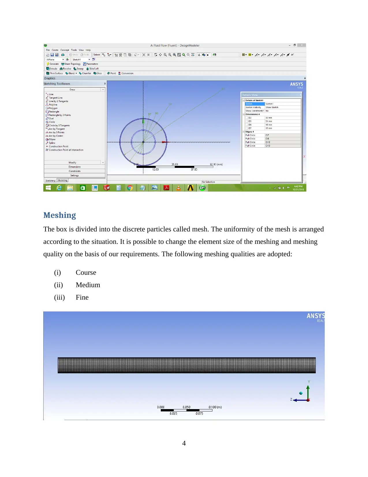
1. Geometry: The first step is to obtain a sketch according to the requirements; extrude or
import the geometry or model in IGS or .stp format; apply the fill according to the
requirements in the mode.
2. The inlet pipe has 15 diameters and the outer pipes have 30 diameters. The thickness of
the pipe is given as 5mm. (Ullman,2017)
3
Document Page
Meshing
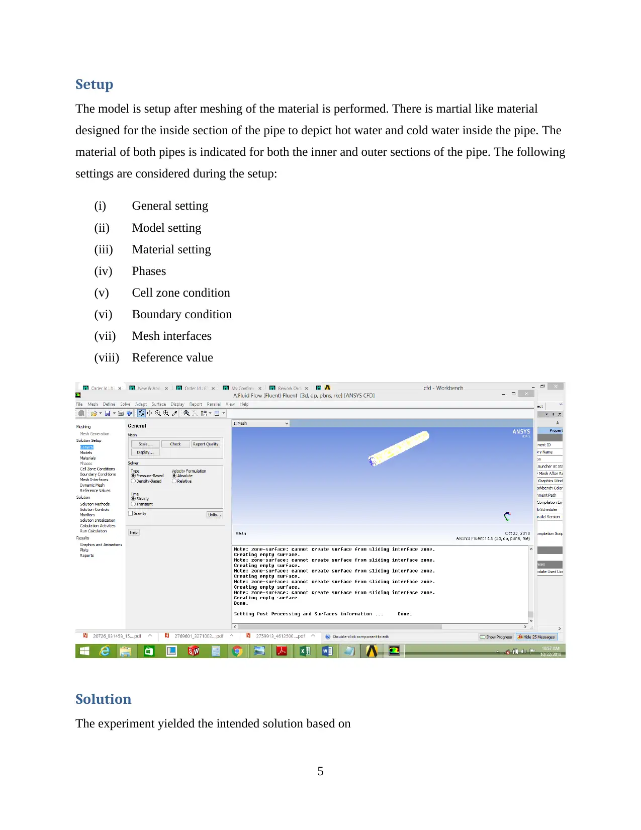
The box is divided into the discrete particles called mesh. The uniformity of the mesh is arranged
according to the situation. It is possible to change the element size of the meshing and meshing
quality on the basis of our requirements. The following meshing qualities are adopted:
(i) Course
(ii) Medium
(iii) Fine
4

Paraphrase This Document

Need a fresh take? Get an instant paraphrase of this document with our AI Paraphraser
Document Page
Setup
The model is setup after meshing of the material is performed. There is martial like material
designed for the inside section of the pipe to depict hot water and cold water inside the pipe. The
material of both pipes is indicated for both the inner and outer sections of the pipe. The following
settings are considered during the setup:
(i) General setting
(ii) Model setting
(iii) Material setting
(iv) Phases
(v) Cell zone condition
(vi) Boundary condition
(vii) Mesh interfaces
(viii) Reference value
Solution
The experiment yielded the intended solution based on
5
Document Page
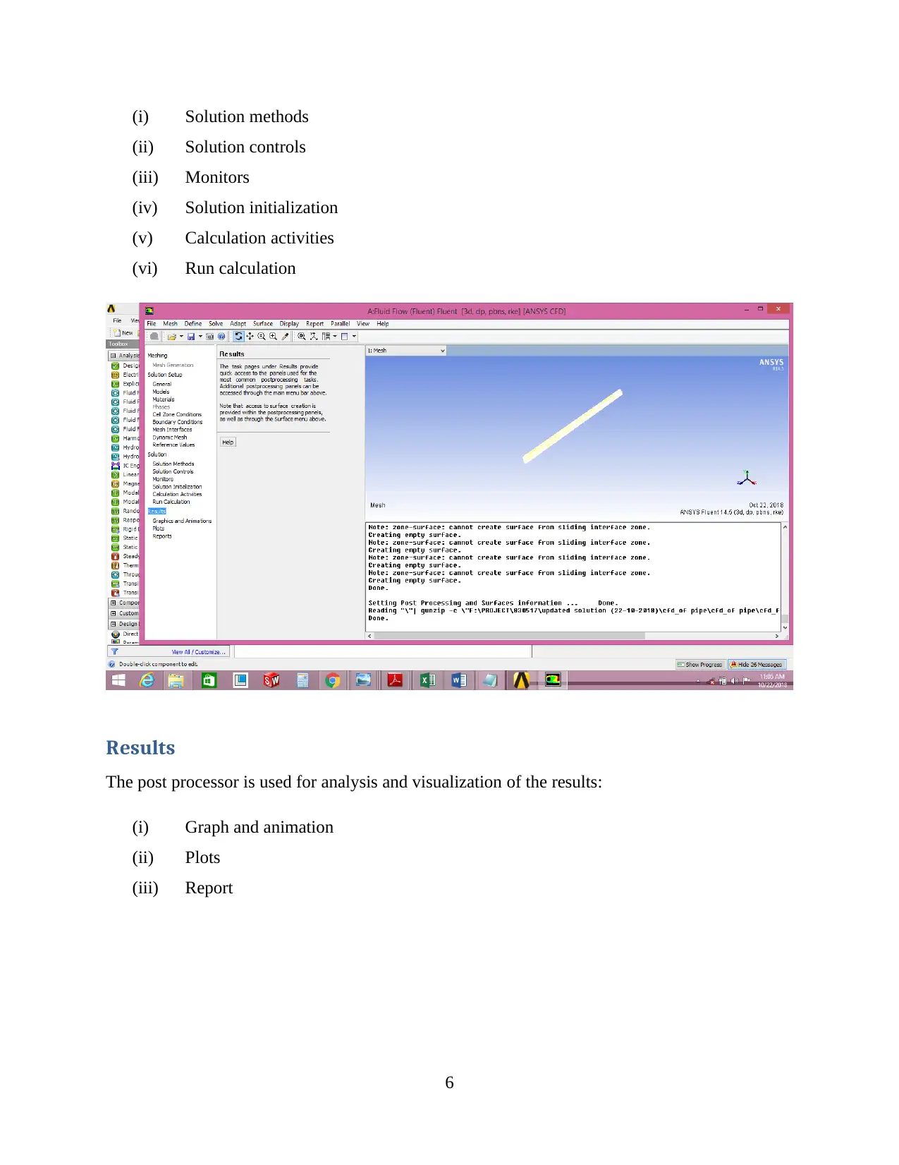
(i) Solution methods
(ii) Solution controls
(iii) Monitors
(iv) Solution initialization
(v) Calculation activities
(vi) Run calculation
Results
The post processor is used for analysis and visualization of the results:
(i) Graph and animation
(ii) Plots
(iii) Report
6
Document Page
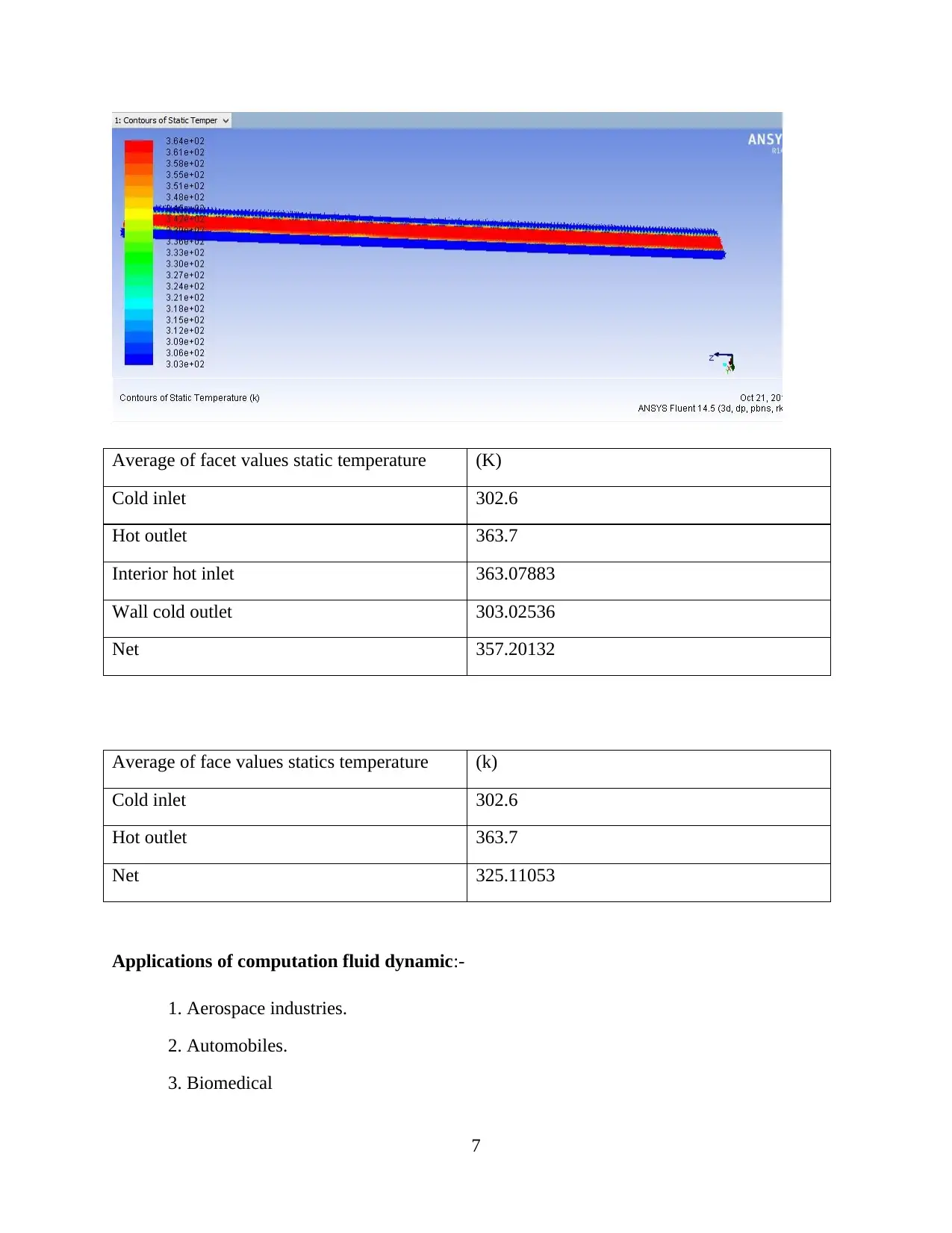
Average of facet values static temperature (K)
Cold inlet 302.6
Hot outlet 363.7
Interior hot inlet 363.07883
Wall cold outlet 303.02536
Net 357.20132
Average of face values statics temperature (k)
Cold inlet 302.6
Hot outlet 363.7
Net 325.11053
Applications of computation fluid dynamic:-
1. Aerospace industries.
2. Automobiles.
3. Biomedical
7

Secure Best Marks with AI Grader

Need help grading? Try our AI Grader for instant feedback on your assignments.
Document Page
4. Chemical processing.
5. Marines
6. Oil and gas piping industries.
7. Sports, etc.
Advantages of computational fluid dynamic
1. Eliminate the process of experimentation in laboratories.
2. Provide better details.
3. Provide better predictions in a short period of time.
4. Provides better and fast design meeting all the environmental regulations and ensures
industry quality.
5. Provide shorter design cycles and supply products faster in the market.
6. Easy to install with minimum downtime.
7. Allow rapid prototyping.
8. More cost effectively.
9. Higher accuracy of the result
10. We analysis the model without physical damage of our proto type.
Disadvantages of computation fluid dynamic
1. It has high investment cost.
2. Required skill person for handling the project.
References
J., Y., 2005. Knowledge Incorporation in Evolutionary Computation. Berlin: Springer.
Lomax, H., H., h. & Zingg, D. W., 2013. Fundamentals of Computational Fluid Dynamics.
s.l.:Springer Science & Business Media.
8
Document Page
9
1 out of 9
[object Object]

Your All-in-One AI-Powered Toolkit for Academic Success.

Available 24*7 on WhatsApp / Email

[object Object]