Computer Aided Design and Computer Aided Manufacturing of a Designed Component 18 COMPUTER AIDED DESIGN AND COMPUTER AIDED MANUFACTURING OF A DESIGNED COMPONENT
Design a component using SolidWorks and SolidCAM, produce machine code for CNC milling operation, and discuss manufacturing strategy implications.
19 Pages1937 Words25 Views
Added on 2022-08-12
About This Document
Please read the highlighted parts with the file attached carefully, please
Computer Aided Design and Computer Aided Manufacturing of a Designed Component 18 COMPUTER AIDED DESIGN AND COMPUTER AIDED MANUFACTURING OF A DESIGNED COMPONENT
Design a component using SolidWorks and SolidCAM, produce machine code for CNC milling operation, and discuss manufacturing strategy implications.
Added on 2022-08-12
ShareRelated Documents
Computer Aided Design and Computer Aided Manufacturing of a Designed Component 1
COMPUTER AIDED DESIGN AND COMPUTER AIDED MANUFACTURING OF A
DESIGNED COMPONENT
Name of student
Course
Instructor
Institution filiation
Location
Date
COMPUTER AIDED DESIGN AND COMPUTER AIDED MANUFACTURING OF A
DESIGNED COMPONENT
Name of student
Course
Instructor
Institution filiation
Location
Date

Computer Aided Design and Computer Aided Manufacturing of a Designed Component 2
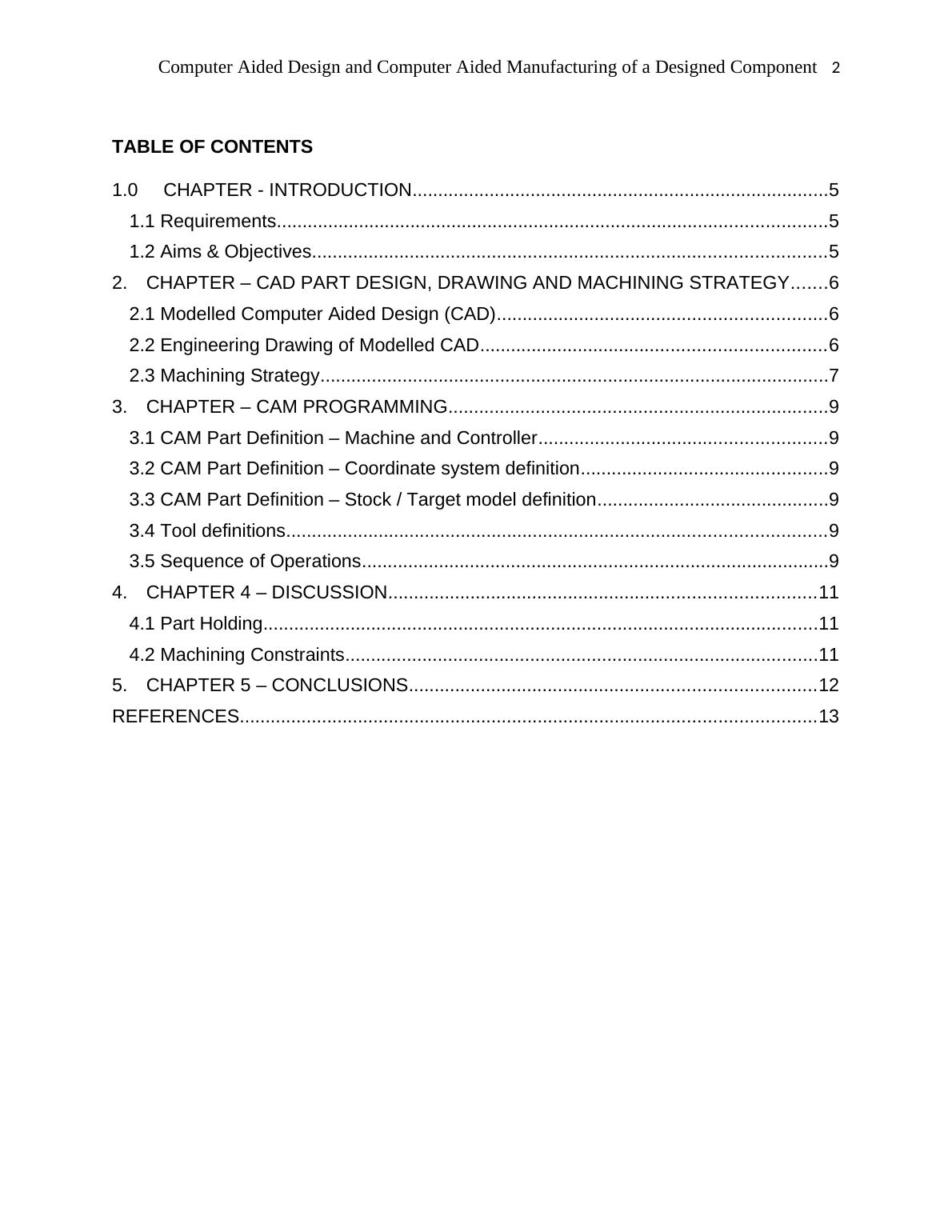
TABLE OF CONTENTS
1.0 CHAPTER - INTRODUCTION.................................................................................5
1.1 Requirements...........................................................................................................5
1.2 Aims & Objectives....................................................................................................5
2. CHAPTER – CAD PART DESIGN, DRAWING AND MACHINING STRATEGY.......6
2.1 Modelled Computer Aided Design (CAD)................................................................6
2.2 Engineering Drawing of Modelled CAD...................................................................6
2.3 Machining Strategy...................................................................................................7
3. CHAPTER – CAM PROGRAMMING..........................................................................9
3.1 CAM Part Definition – Machine and Controller........................................................9
3.2 CAM Part Definition – Coordinate system definition................................................9
3.3 CAM Part Definition – Stock / Target model definition.............................................9
3.4 Tool definitions.........................................................................................................9
3.5 Sequence of Operations...........................................................................................9
4. CHAPTER 4 – DISCUSSION...................................................................................11
4.1 Part Holding............................................................................................................11
4.2 Machining Constraints............................................................................................11
5. CHAPTER 5 – CONCLUSIONS...............................................................................12
REFERENCES................................................................................................................13

Computer Aided Design and Computer Aided Manufacturing of a Designed Component 3
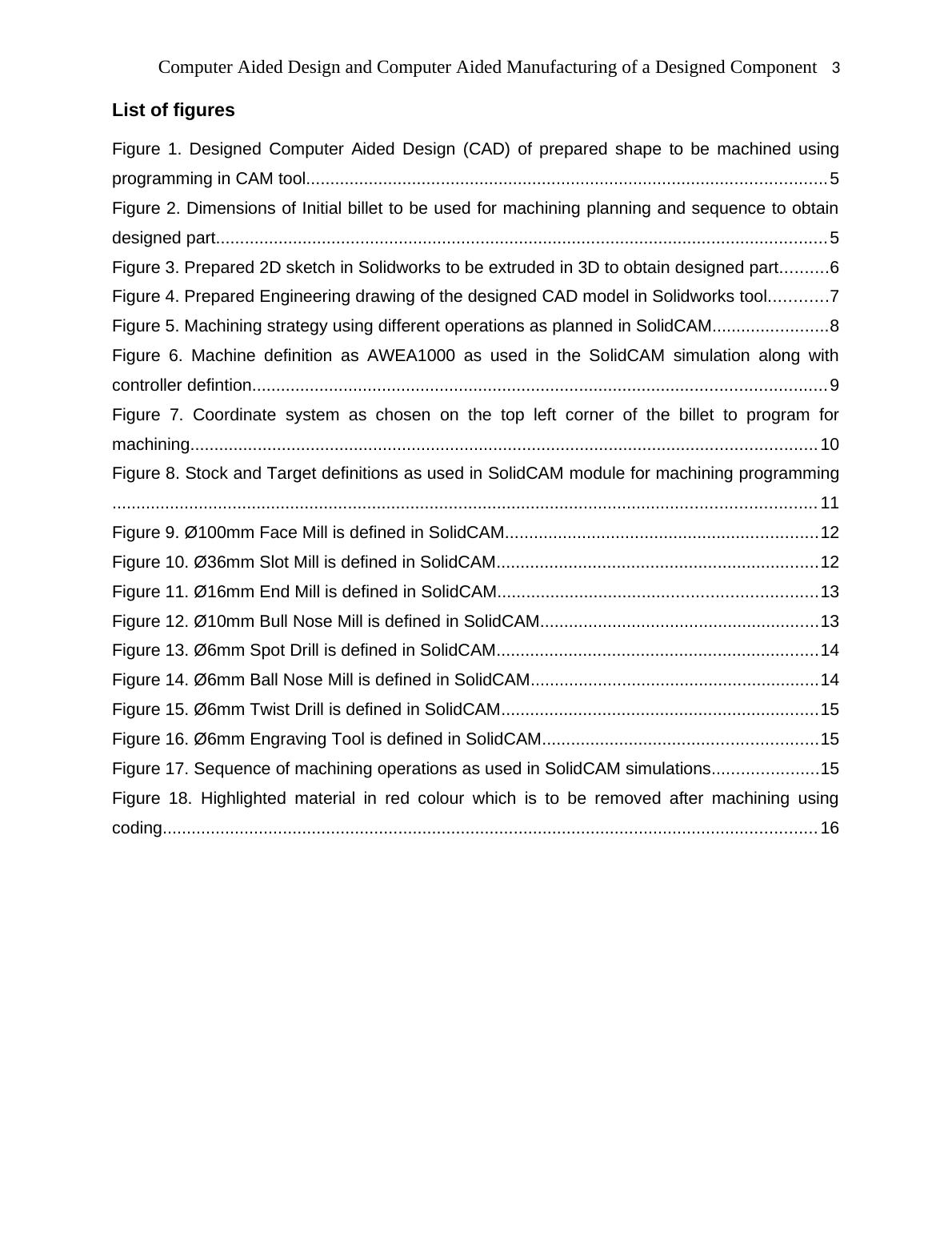
List of figures
Figure 1. Designed Computer Aided Design (CAD) of prepared shape to be machined using
programming in CAM tool............................................................................................................ 5
Figure 2. Dimensions of Initial billet to be used for machining planning and sequence to obtain
designed part............................................................................................................................... 5
Figure 3. Prepared 2D sketch in Solidworks to be extruded in 3D to obtain designed part..........6
Figure 4. Prepared Engineering drawing of the designed CAD model in Solidworks tool............7
Figure 5. Machining strategy using different operations as planned in SolidCAM........................8
Figure 6. Machine definition as AWEA1000 as used in the SolidCAM simulation along with
controller defintion....................................................................................................................... 9
Figure 7. Coordinate system as chosen on the top left corner of the billet to program for
machining.................................................................................................................................. 10
Figure 8. Stock and Target definitions as used in SolidCAM module for machining programming
.................................................................................................................................................. 11
Figure 9. Ø100mm Face Mill is defined in SolidCAM.................................................................12
Figure 10. Ø36mm Slot Mill is defined in SolidCAM...................................................................12
Figure 11. Ø16mm End Mill is defined in SolidCAM..................................................................13
Figure 12. Ø10mm Bull Nose Mill is defined in SolidCAM..........................................................13
Figure 13. Ø6mm Spot Drill is defined in SolidCAM...................................................................14
Figure 14. Ø6mm Ball Nose Mill is defined in SolidCAM............................................................14
Figure 15. Ø6mm Twist Drill is defined in SolidCAM..................................................................15
Figure 16. Ø6mm Engraving Tool is defined in SolidCAM.........................................................15
Figure 17. Sequence of machining operations as used in SolidCAM simulations......................15
Figure 18. Highlighted material in red colour which is to be removed after machining using
coding........................................................................................................................................ 16

Computer Aided Design and Computer Aided Manufacturing of a Designed Component 4
1.0 CHAPTER - INTRODUCTION
Computer Aided Design (CAD) is a very powerful method to replace the conventional hand
drawn part development method which can now be assisted with Computer Aided Manufacturing
(CAM) for manufacturing planning.
1.1 Requirements
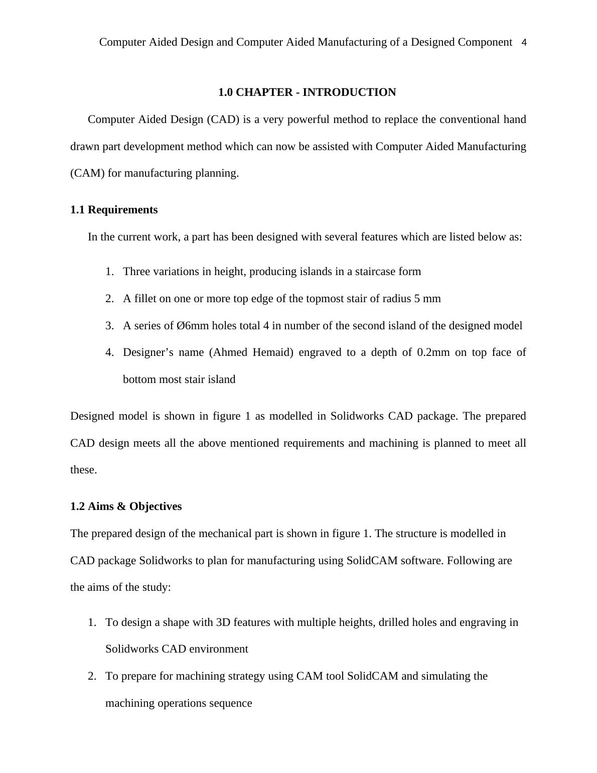
In the current work, a part has been designed with several features which are listed below as:
1. Three variations in height, producing islands in a staircase form
2. A fillet on one or more top edge of the topmost stair of radius 5 mm
3. A series of Ø6mm holes total 4 in number of the second island of the designed model
4. Designer’s name (Ahmed Hemaid) engraved to a depth of 0.2mm on top face of
bottom most stair island
Designed model is shown in figure 1 as modelled in Solidworks CAD package. The prepared
CAD design meets all the above mentioned requirements and machining is planned to meet all
these.
1.2 Aims & Objectives
The prepared design of the mechanical part is shown in figure 1. The structure is modelled in
CAD package Solidworks to plan for manufacturing using SolidCAM software. Following are
the aims of the study:
1. To design a shape with 3D features with multiple heights, drilled holes and engraving in
Solidworks CAD environment
2. To prepare for machining strategy using CAM tool SolidCAM and simulating the
machining operations sequence

End of preview
Want to access all the pages? Upload your documents or become a member.
Related Documents
Computer Integrated Manufacturing (CIM) - Research Project Submission 4lg...
|6
|888
|212
