Computer Architecture: Cache Memory Analysis and Implementation
VerifiedAdded on 2020/05/28
|2
|305
|134
Homework Assignment
AI Summary
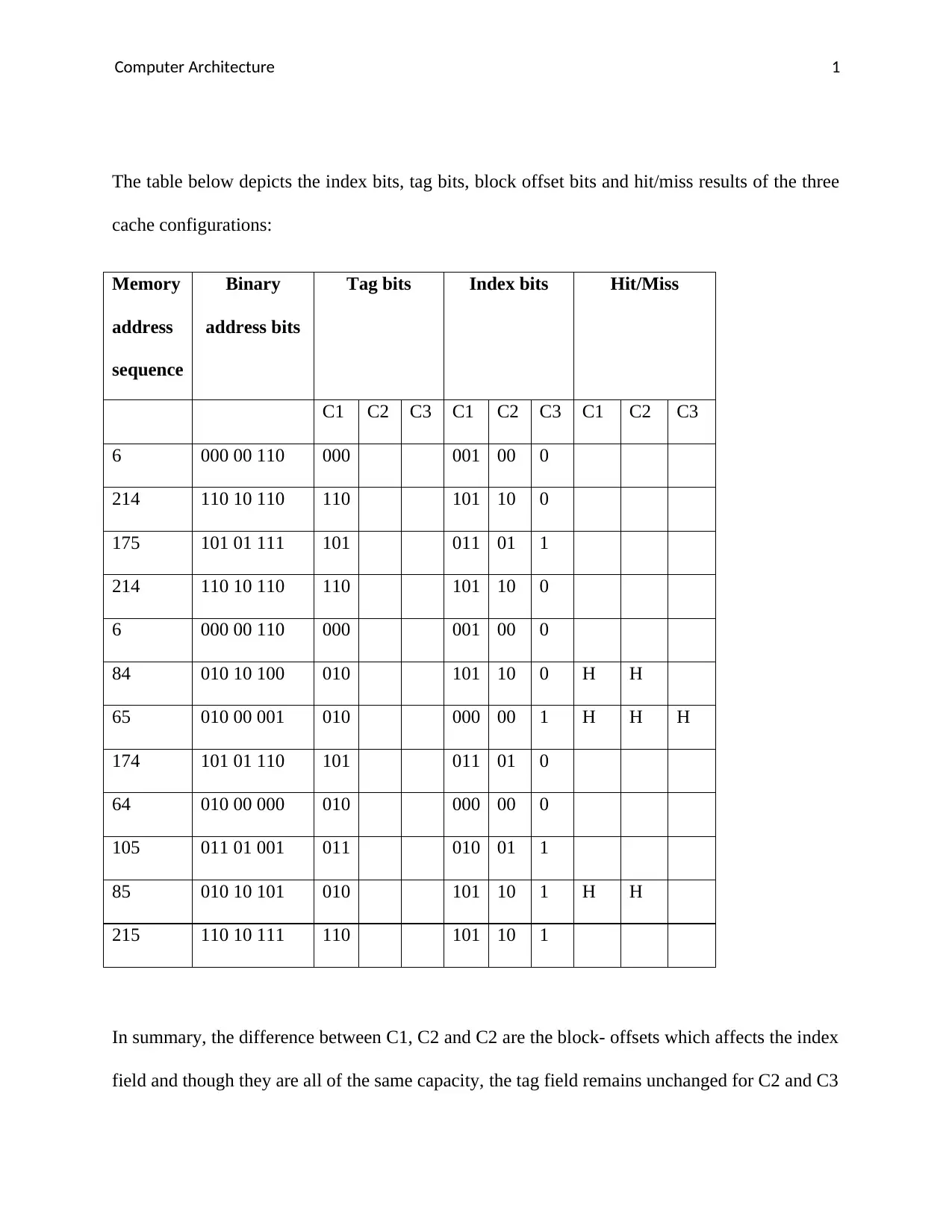
This assignment analyzes cache memory performance by examining the impact of index bits, tag bits, and block offsets on hit/miss results in three different cache configurations (C1, C2, and C3). The analysis is based on a given memory address sequence and involves understanding how different configurations affect the cache's ability to store and retrieve data efficiently. The configurations differ in block sizes, which influences the index and offset fields. The assignment includes a table of memory addresses, binary representations, and hit/miss results for each configuration. The references include works on the architecture of cognition and transactional memory architecture and implementation.
1 out of 2
Related Documents


Your All-in-One AI-Powered Toolkit for Academic Success.
+13062052269
info@desklib.com
Available 24*7 on WhatsApp / Email
![[object Object]](/_next/static/media/star-bottom.7253800d.svg)
Copyright © 2020–2026 A2Z Services. All Rights Reserved. Developed and managed by ZUCOL.