Computing and Information Systems/Creative Computing
VerifiedAdded on 2023/04/21
|6
|1230
|266
AI Summary
This document discusses various topics related to Computing and Information Systems/Creative Computing. It covers the representation of decimal numbers in IEEE 754 format, two's complement addition, decoder construction, memory addressing, and cache memory.
Contribute Materials
Your contribution can guide someone’s learning journey. Share your
documents today.
Running head: COMPUTING AND INFORMATION SYSTEMS/CREATIVE
COMPUTING
COMPUTING AND INFORMATION SYSTEMS/CREATIVE COMPUTING
Name of the Student
Name of the University
Author Note
COMPUTING
COMPUTING AND INFORMATION SYSTEMS/CREATIVE COMPUTING
Name of the Student
Name of the University
Author Note
Secure Best Marks with AI Grader
Need help grading? Try our AI Grader for instant feedback on your assignments.
1COMPUTING AND INFORMATION SYSTEMS/CREATIVE COMPUTING
Question 1:
a. The representation of the positive decimal number 1025.25 in IEEE 754 32-
bit format is given by, 0 1000 1001 0000 0000 0101 0000 0000 000
Now, the steps to transform the decimal number into binary format is shown below.
1025.2510 = 10000000001.012 = 10000000001.01*2(^0) = 1.000000000101*2(^10).
a. Hence, the exponent is 10 and biasing it by 127 gives 10+127 = 137. So, normalizing
the biased exponent gives 137 = 10001001. Now, the mantissa is 1.000000000101.
The 1 in the left of radix point is not stored in IEEE 754 32-bit format (Tang,
Schneider and Tsen 2015). Hence, the number in the IEEE 754 32-bit format is given
below.
Sign Exponent Mantissa
0 1000 1001 0000 0000 0101 0000 0000
000
b. The IEEE 754 number is given by,
1.10111 x 2^(−130)
In IEEE 754 32-bit denormalised form the number is given as follows. The exponent
is given in decimal form.
Sign Exponent Mantissa
0 -13010 10111 000 0000 0000 0000
000
Question 2:
2COMPUTING AND INFORMATION SYSTEMS/CREATIVE COMPUTING
a. The two’s complement addition is given by
1001 + 1010 = 10011. Now, in decimal equivalent 1001 = -1 and 1010 = -2. Now, the
addition of two negative numbers gives a negative number. Now, in 2’s complement
addition the extra bit is discarded and the sign bit of result is 0 which is wrong
(Nannarelli 2017). Hence, there is an overflow which means the magnitude of result is
too large to represent in 4 bit format.
b. After sign extending the two numbers in 6 bits the numbers will be
111001 and 111010. The sign bit which is 1 is moved to the leftmost position and
the extra two bits are filled with copy of the sign bit which is 1.
Now, addition gives,
111001
+111010
=1110011
Now, discarding the extra bit in result and representing in 6 bit format the result is
110011. Here, the sign bit is the left most bit which is 1 or the result is negative
(Nannarelli 2017). Now, removing the sign bit and extra two bits from left which
were added to the 4 bit signed binary number, the magnitude bits are 011 = 3.
Hence, the result is -3 and there is no overflow.
Question 3:
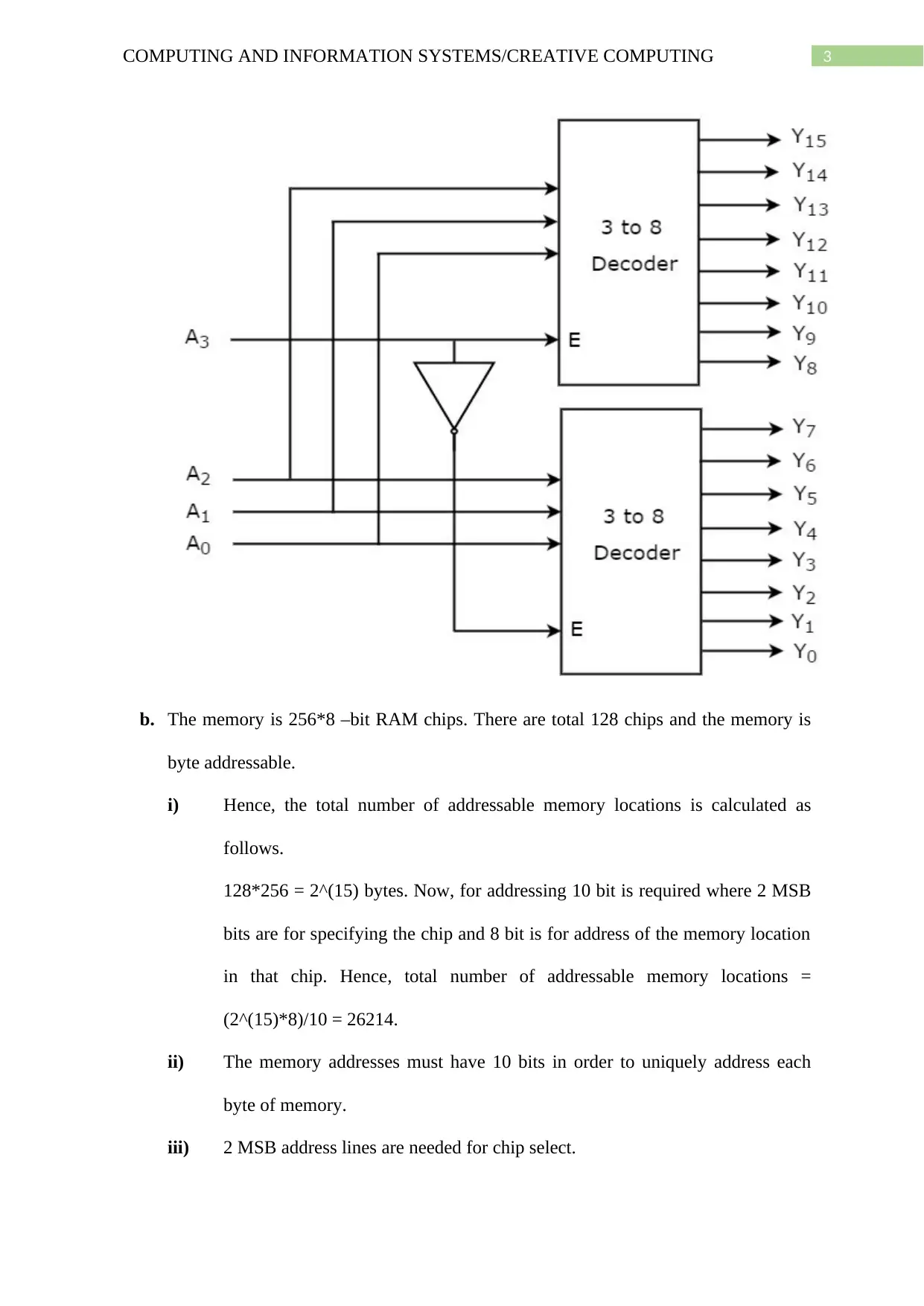
a. A decoder with 4 inputs and 16 outputs is shown below. A 4 to 16 decoder is
constructed using two 3 to 8 decoder (Kirichenko et al. 2015).
3COMPUTING AND INFORMATION SYSTEMS/CREATIVE COMPUTING
b. The memory is 256*8 –bit RAM chips. There are total 128 chips and the memory is
byte addressable.
i) Hence, the total number of addressable memory locations is calculated as
follows.
128*256 = 2^(15) bytes. Now, for addressing 10 bit is required where 2 MSB
bits are for specifying the chip and 8 bit is for address of the memory location
in that chip. Hence, total number of addressable memory locations =
(2^(15)*8)/10 = 26214.
ii) The memory addresses must have 10 bits in order to uniquely address each
byte of memory.
iii) 2 MSB address lines are needed for chip select.
Secure Best Marks with AI Grader
Need help grading? Try our AI Grader for instant feedback on your assignments.
4COMPUTING AND INFORMATION SYSTEMS/CREATIVE COMPUTING
iv) 8 address lines are needed for selecting memory location on a chip.
c. The memory size is same as before which is 128 numbers of 256*8-bit RAM chips.
i) Now, when the memory is word addressable and a word is of 64 bit size then
the addressable memory locations = (128*256*8)/64 = 4096 = 2^(12).
ii) Now, the address of a word is given as 1111 1010 1001.
Now, the first four bits represents the chip select address and last 8 bits are the
address of the portion of word in that chip. Hence, the last 8 bits are used to
identify the word in that chip (Harris and Harris 2015). Now, the chip select
bits are 4 so total of 16 chips are there address from 0 to 15 and the total word
is equally distributed in every chip in the address location 1010 1001.
Question 4:
The cache memory is basically a segment of the main memory which operates by the
principle of locality of reference. The locality of reference consists of two principles namely
temporal locality and the spatial locality. The temporal locality is the property of the
processor by which it access the recently used memory locations. While, the spatial locality is
the property for which the locations accessed by the processor within a concentrated region of
memory addresses are noted. As the instructions are accessed in sequential manner hence the
addresses that are close to each other can be identified (Jayakumar et al. 2015). Now, in case
of memory read or reading a word from the memory it is first checked that whether the word
is in cache and if it is in cache then it is known as cache hit and word is read from the cache.
Otherwise the cache miss occurs and the word along with some words in its adjacent
locations are transferred from main memory to cache memory and then the word is
transferred to the CPU from cache. Same case happens for writing words also.
5COMPUTING AND INFORMATION SYSTEMS/CREATIVE COMPUTING
References:
Harris, S. and Harris, D., 2015. Digital design and computer architecture: arm edition.
Morgan Kaufmann.
Jayakumar, N., Singh, S., Patil, S.H. and Joshi, S.D., 2015. Evaluation Parameters of
Infrastructure Resources Required for Integrating Parallel Computing Algorithm and
Distributed File System. IJSTE-Int. J. Sci. Technol. Eng, 1(12), pp.251-254.
Kirichenko, A.F., Vernik, I.V., Mukhanov, O.A. and Ohki, T.A., 2015. ERSFQ 4-to-16
decoder for energy-efficient RAM. IEEE Trans. Appl. Supercond, 25(3), p.1301304.
Nannarelli, A., 2017, September. A multi-format floating-point multiplier for power-efficient
operations. In System-on-Chip Conference (SOCC), 2017 30th IEEE International (pp. 351-
356). IEEE.
Tang, P.T.P., Schneider, E. and Tsen, C., 2015. A Software Implementation of the IEEE
754R Decimal Floating-Point Arithmetic Using the Binary Encoding Format. Computer
Arithmetic: Volume III, 3, p.411.
1 out of 6
Related Documents
Your All-in-One AI-Powered Toolkit for Academic Success.
+13062052269
info@desklib.com
Available 24*7 on WhatsApp / Email
Unlock your academic potential
© 2024 | Zucol Services PVT LTD | All rights reserved.