Advanced Design Report: MKAE 1083 Reinforced Concrete Footbridge
VerifiedAdded on 2023/06/12
|10
|1498
|143
Report
AI Summary
This report presents a comprehensive design for a reinforced concrete pedestrian bridge spanning a dual carriageway, adhering to Eurocode 2 standards. The project involves a two-phased construction approach, ensuring minimal traffic disruption. The design considers factors such as material specifications (concrete grade, steel yield strength), loading conditions (dead loads, live loads), durability, fire resistance, and bond requirements. Key design elements include slab design, beam design (incorporating moment distribution analysis), short and slender column design, and footing design. The report details calculations for determining reinforcement requirements, shear checks, deflection checks, and cracking checks. It also addresses identified issues, such as potential errors in manual design, and proposes solutions like utilizing AutoCAD software for precise measurements. This document provides a detailed overview of the design process and considerations involved in creating a safe and efficient pedestrian bridge structure.

COMPETENCY
DEMONSTRATION REPORT
Career Episode 2
MOHAMED, MOHAMOUD
DEMONSTRATION REPORT
Career Episode 2
MOHAMED, MOHAMOUD
Paraphrase This Document
Need a fresh take? Get an instant paraphrase of this document with our AI Paraphraser
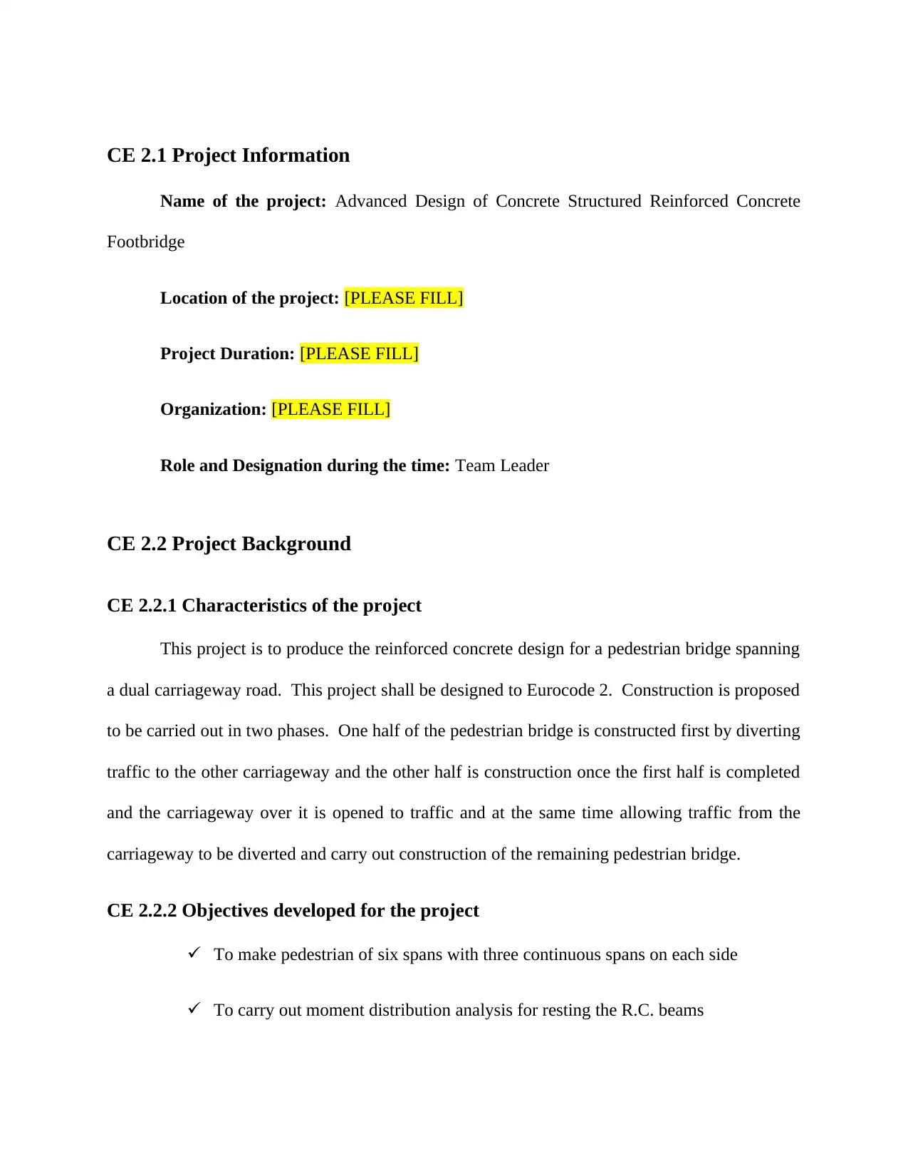
CE 2.1 Project Information
Name of the project: Advanced Design of Concrete Structured Reinforced Concrete
Footbridge
Location of the project: [PLEASE FILL]
Project Duration: [PLEASE FILL]
Organization: [PLEASE FILL]
Role and Designation during the time: Team Leader
CE 2.2 Project Background
CE 2.2.1 Characteristics of the project
This project is to produce the reinforced concrete design for a pedestrian bridge spanning
a dual carriageway road. This project shall be designed to Eurocode 2. Construction is proposed
to be carried out in two phases. One half of the pedestrian bridge is constructed first by diverting
traffic to the other carriageway and the other half is construction once the first half is completed
and the carriageway over it is opened to traffic and at the same time allowing traffic from the
carriageway to be diverted and carry out construction of the remaining pedestrian bridge.
CE 2.2.2 Objectives developed for the project
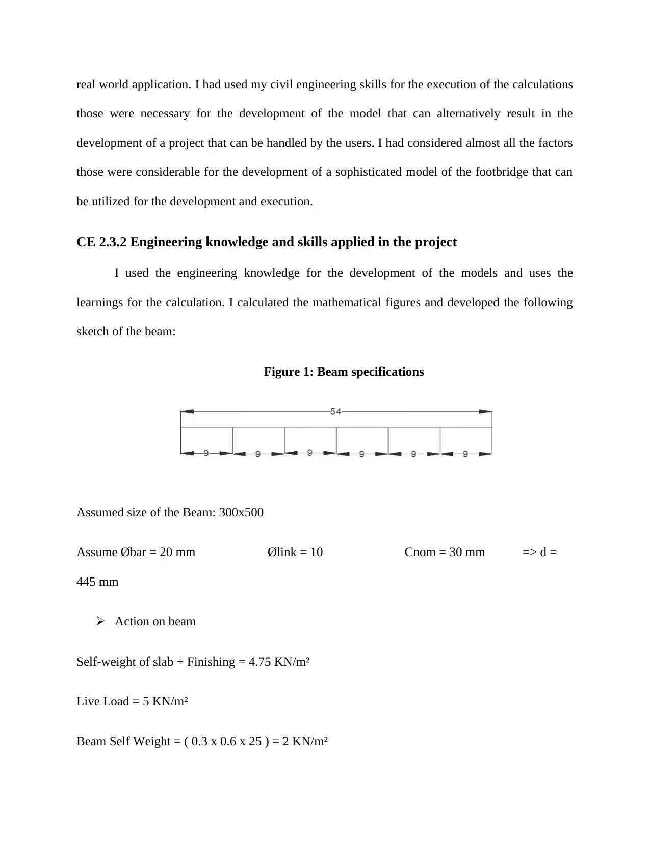
To make pedestrian of six spans with three continuous spans on each side
To carry out moment distribution analysis for resting the R.C. beams
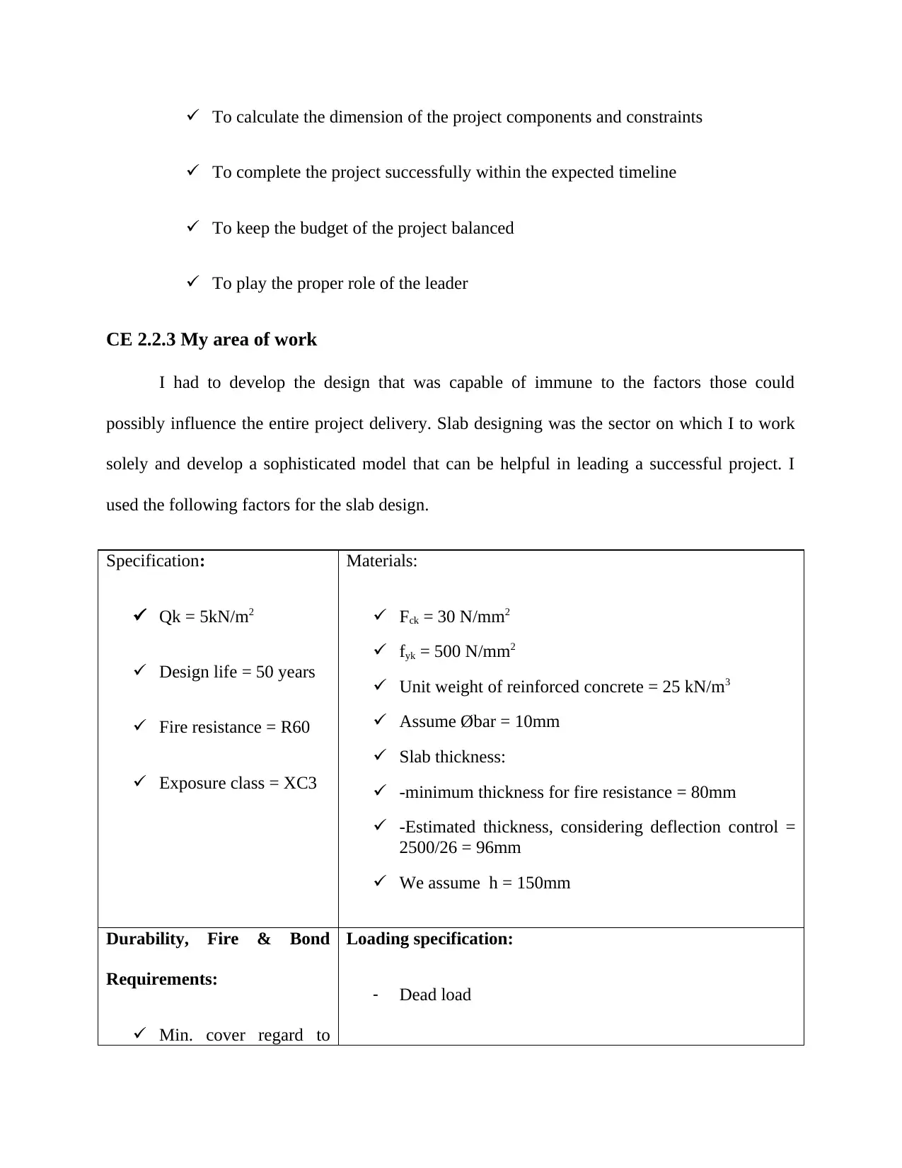
To calculate the dimension of the project components and constraints
To complete the project successfully within the expected timeline
To keep the budget of the project balanced
To play the proper role of the leader
CE 2.2.3 My area of work
I had to develop the design that was capable of immune to the factors those could
possibly influence the entire project delivery. Slab designing was the sector on which I to work
solely and develop a sophisticated model that can be helpful in leading a successful project. I
used the following factors for the slab design.
Specification:
Qk = 5kN/m2
Design life = 50 years
Fire resistance = R60
Exposure class = XC3
Materials:
Fck = 30 N/mm2
fyk = 500 N/mm2
Unit weight of reinforced concrete = 25 kN/m3
Assume Øbar = 10mm
Slab thickness:
-minimum thickness for fire resistance = 80mm
-Estimated thickness, considering deflection control =
2500/26 = 96mm
We assume h = 150mm
Durability, Fire & Bond
Requirements:
Min. cover regard to
Loading specification:
- Dead load
⊘ This is a preview!⊘
Do you want full access?
Subscribe today to unlock all pages.

Trusted by 1+ million students worldwide
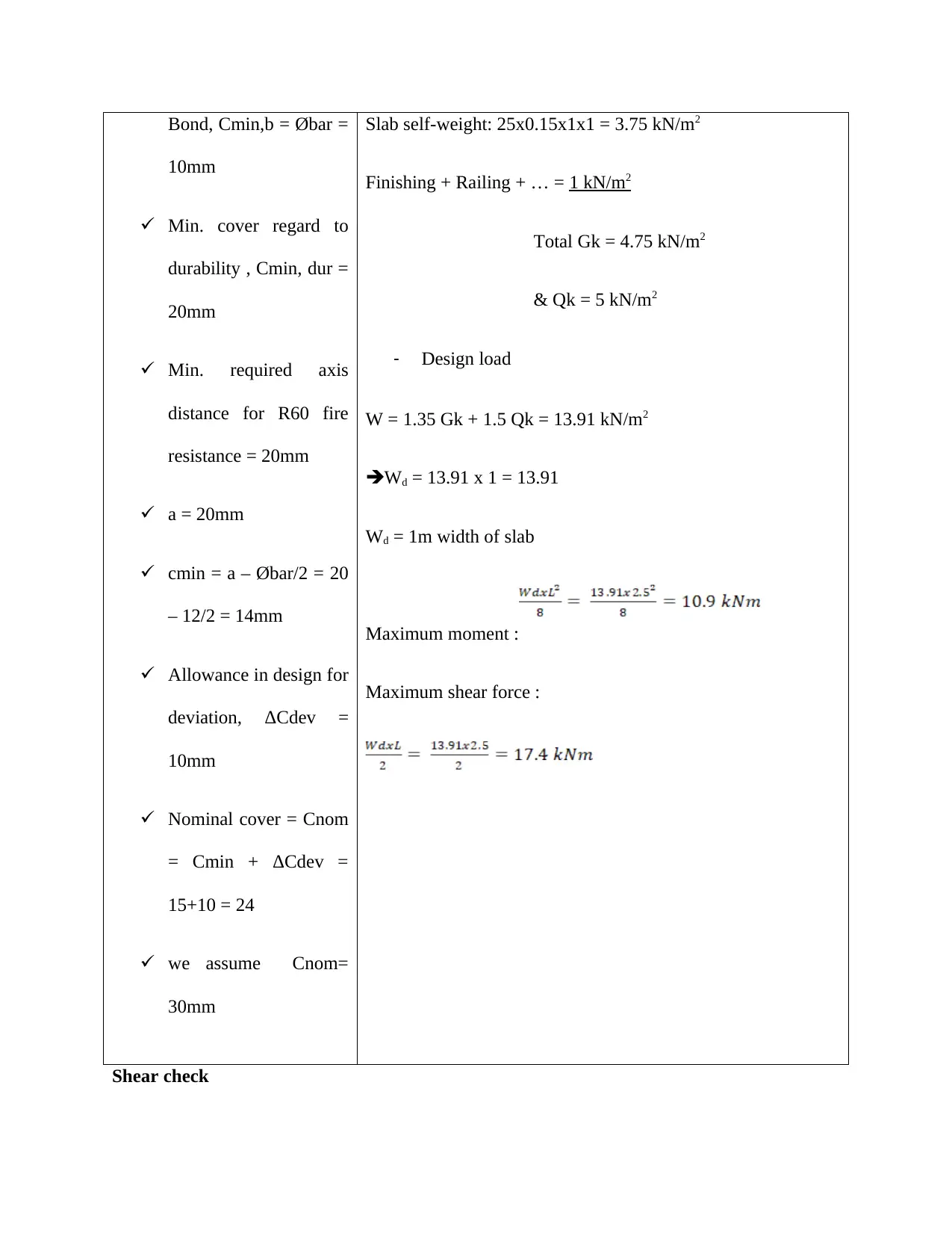
Bond, Cmin,b = Øbar =
10mm
Min. cover regard to
durability , Cmin, dur =
20mm
Min. required axis
distance for R60 fire
resistance = 20mm
a = 20mm
cmin = a – Øbar/2 = 20
– 12/2 = 14mm
Allowance in design for
deviation, ΔCdev =
10mm
Nominal cover = Cnom
= Cmin + ΔCdev =
15+10 = 24
we assume Cnom=
30mm
Slab self-weight: 25x0.15x1x1 = 3.75 kN/m2
Finishing + Railing + … = 1 kN/m2
Total Gk = 4.75 kN/m2
& Qk = 5 kN/m2
- Design load
W = 1.35 Gk + 1.5 Qk = 13.91 kN/m2
Wd = 13.91 x 1 = 13.91
Wd = 1m width of slab
Maximum moment :
Maximum shear force :
Shear check
10mm
Min. cover regard to
durability , Cmin, dur =
20mm
Min. required axis
distance for R60 fire
resistance = 20mm
a = 20mm
cmin = a – Øbar/2 = 20
– 12/2 = 14mm
Allowance in design for
deviation, ΔCdev =
10mm
Nominal cover = Cnom
= Cmin + ΔCdev =
15+10 = 24
we assume Cnom=
30mm
Slab self-weight: 25x0.15x1x1 = 3.75 kN/m2
Finishing + Railing + … = 1 kN/m2
Total Gk = 4.75 kN/m2
& Qk = 5 kN/m2
- Design load
W = 1.35 Gk + 1.5 Qk = 13.91 kN/m2
Wd = 13.91 x 1 = 13.91
Wd = 1m width of slab
Maximum moment :
Maximum shear force :
Shear check
Paraphrase This Document
Need a fresh take? Get an instant paraphrase of this document with our AI Paraphraser
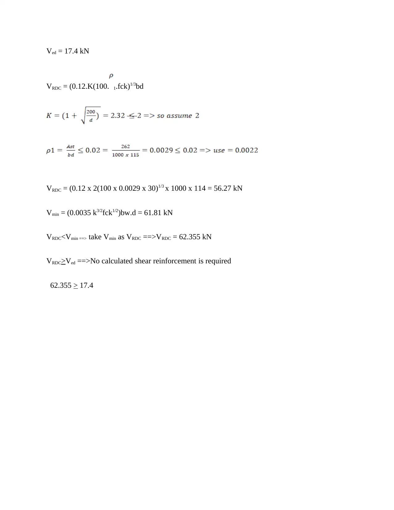
Ved = 17.4 kN
VRDC = (0.12.K(100. 1.fck)1/3bd
VRDC = (0.12 x 2(100 x 0.0029 x 30)1/3 x 1000 x 114 = 56.27 kN
Vmin = (0.0035 k3/2fck1/2)bw.d = 61.81 kN
VRDC<Vmin ==> take Vmin as VRDC ==>VRDC = 62.355 kN
VRDC>Ved ==>No calculated shear reinforcement is required
62.355 > 17.4
VRDC = (0.12.K(100. 1.fck)1/3bd
VRDC = (0.12 x 2(100 x 0.0029 x 30)1/3 x 1000 x 114 = 56.27 kN
Vmin = (0.0035 k3/2fck1/2)bw.d = 61.81 kN
VRDC<Vmin ==> take Vmin as VRDC ==>VRDC = 62.355 kN
VRDC>Ved ==>No calculated shear reinforcement is required
62.355 > 17.4
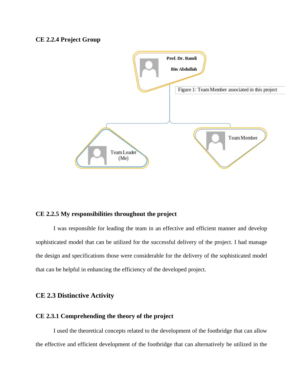
CE 2.2.4 Project Group
CE 2.2.5 My responsibilities throughout the project
I was responsible for leading the team in an effective and efficient manner and develop
sophisticated model that can be utilized for the successful delivery of the project. I had manage
the design and specifications those were considerable for the delivery of the sophisticated model
that can be helpful in enhancing the efficiency of the developed project.
CE 2.3 Distinctive Activity
CE 2.3.1 Comprehending the theory of the project
I used the theoretical concepts related to the development of the footbridge that can allow
the effective and efficient development of the footbridge that can alternatively be utilized in the
⊘ This is a preview!⊘
Do you want full access?
Subscribe today to unlock all pages.

Trusted by 1+ million students worldwide
real world application. I had used my civil engineering skills for the execution of the calculations
those were necessary for the development of the model that can alternatively result in the
development of a project that can be handled by the users. I had considered almost all the factors
those were considerable for the development of a sophisticated model of the footbridge that can
be utilized for the development and execution.
CE 2.3.2 Engineering knowledge and skills applied in the project
I used the engineering knowledge for the development of the models and uses the
learnings for the calculation. I calculated the mathematical figures and developed the following
sketch of the beam:
Figure 1: Beam specifications
Assumed size of the Beam: 300x500
Assume Øbar = 20 mm Ølink = 10 Cnom = 30 mm => d =
445 mm
Action on beam
Self-weight of slab + Finishing = 4.75 KN/m²
Live Load = 5 KN/m²
Beam Self Weight = ( 0.3 x 0.6 x 25 ) = 2 KN/m²
Paraphrase This Document
Need a fresh take? Get an instant paraphrase of this document with our AI Paraphraser
Distributed loads from one way slab :
Dead load = B x N x L = 0.5 x 4.57 x 2.5 = 5.9 KN/m
Ultimate dead load from slab + Beam = ( 5.9 + 2 ) = 8 KN/m = Gk
Live load = B x N x L = 0.5 x 5 x2.5 = 6.25 KN/m
Ultimate live load from slab + Beam = 6.25 KN/m = Qk
Ultimate load from slab &Beam:
= 1.35 Gk + 1.5 Qk
= 1.35 x 8 + 1.5 x 6.25 = 21 KN/m
Maximum load= (1.35 x Gk + 1.5.Qk) =21KN/m
Minimum load= (1.35.Gk) = 10.8KN/m
Load Cases
1. All the spans are with maximum ( 21 KN/m ) load
2. Span 1 and 3 with maximum ( 21 KN/m ) and span 2 with minimum ( 10.8 KN/m )
3. Span 1 and 3 with minimum (10.8 KN/m) and span 2 with maximum (21 KN/m)
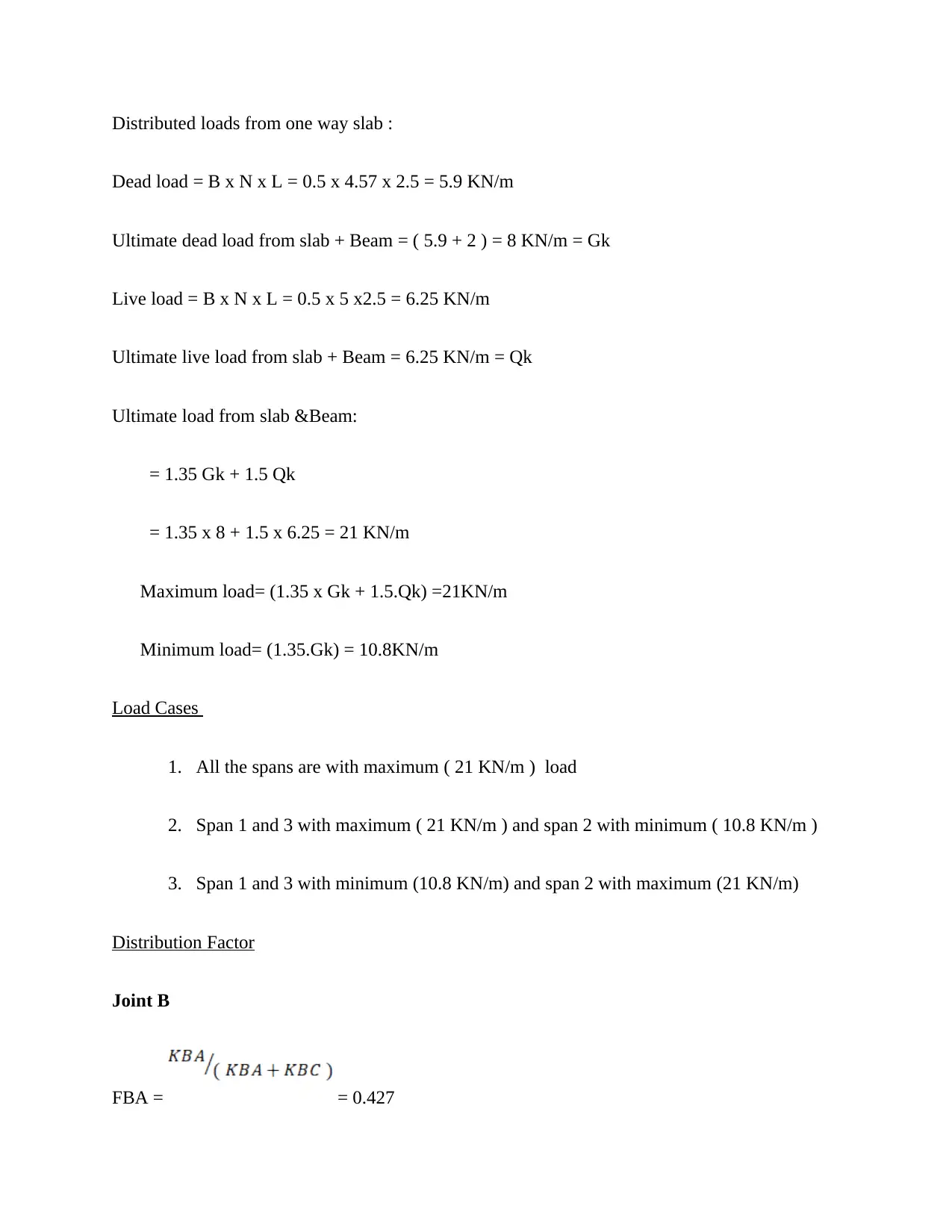
Distribution Factor
Joint B
FBA = = 0.427
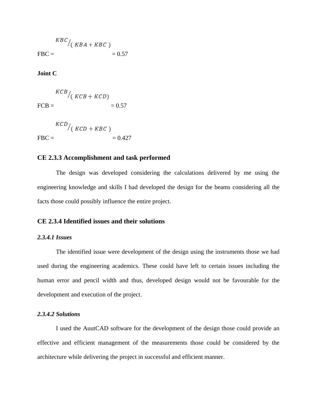
FBC = = 0.57
Joint C
FCB = = 0.57
FBC = = 0.427
CE 2.3.3 Accomplishment and task performed
The design was developed considering the calculations delivered by me using the
engineering knowledge and skills I had developed the design for the beams considering all the
facts those could possibly influence the entire project.
CE 2.3.4 Identified issues and their solutions
2.3.4.1 Issues
The identified issue were development of the design using the instruments those we had
used during the engineering academics. These could have left to certain issues including the
human error and pencil width and thus, developed design would not be favourable for the
development and execution of the project.
2.3.4.2 Solutions
I used the AuutCAD software for the development of the design those could provide an
effective and efficient management of the measurements those could be considered by the
architecture while delivering the project in successful and efficient manner.
⊘ This is a preview!⊘
Do you want full access?
Subscribe today to unlock all pages.

Trusted by 1+ million students worldwide
CE 2.3.5 Plan to produce creative and innovative work
I collected many theoretical research papers proposed by different scholar writers and
engineers and utilized them for the development and growth of the project. I considered many
latent factors those were needed to be considered while delivering the design and model of the
prosed project.
CE 2.3.6 Collaborative work
I had to work in a team and develop the successful project through contributing in the
team work as, the project had to be completed in restricted time. Every team member had
contributed equally that led to the development of a successful design of the skeletal on which
the entire building can be established.
CE 2.4 Project Review
CE 2.4.1 Project Overview and contribution
I developed the project is to produce the reinforced concrete design for a pedestrian
bridge spanning a dual carriageway road. This project shall be designed to Eurocode 2.
Construction is proposed to be carried out in two phases. One half of the pedestrian bridge is
constructed first by diverting traffic to the other carriageway and the other half is construction
once the first half is completed and the carriageway over it is opened to traffic and at the same
time allowing traffic from the carriageway to be diverted and carry out construction of the
remaining pedestrian bridge. I had to develop a sophisticated model for the designing of the
concrete slabs those could be utilized for the development of the bridges necessary for the
development and execution of the bridges.
1 out of 10
Your All-in-One AI-Powered Toolkit for Academic Success.
+13062052269
info@desklib.com
Available 24*7 on WhatsApp / Email
![[object Object]](/_next/static/media/star-bottom.7253800d.svg)
Unlock your academic potential
Copyright © 2020–2026 A2Z Services. All Rights Reserved. Developed and managed by ZUCOL.