SRR720 Concrete Structures Project: Column & Beam Design Report
VerifiedAdded on 2023/04/03
|57
|5014
|74
Project
AI Summary
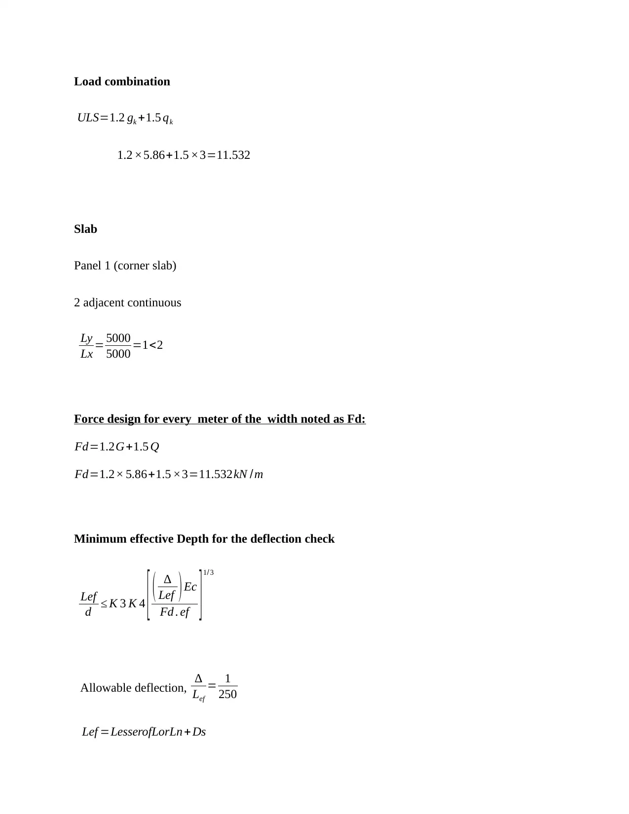
This project report details the design of columns and beams for an eight-story office building located in Sydney's Central Business District, focusing on the structural elements below the ground floor. The design process includes load calculations considering superimposed loads and live loads, as well as load combinations for ultimate limit state (ULS). Slab panels are analyzed for bending moments and reinforcement requirements, with checks for deflection, shear, and cracking control. The design incorporates Australian standards (AS 3600) for concrete structures. The report also covers the transfer of loads to beams, specifically addressing edge beams and continuous beams, including calculations for dead load, live load, and moment/shear force determination. Deflection checks are performed to ensure structural integrity and compliance with relevant standards. The document also includes concept maps and risk management strategies relevant to construction.


1 out of 57
Your All-in-One AI-Powered Toolkit for Academic Success.
+13062052269
info@desklib.com
Available 24*7 on WhatsApp / Email
![[object Object]](/_next/static/media/star-bottom.7253800d.svg)
Copyright © 2020–2025 A2Z Services. All Rights Reserved. Developed and managed by ZUCOL.