Case Study: Analysis of Condition Monitoring in Automotive Final Drive

Verified

Added on  2023/04/23

|22
|1103
|150
Case Study
AI Summary
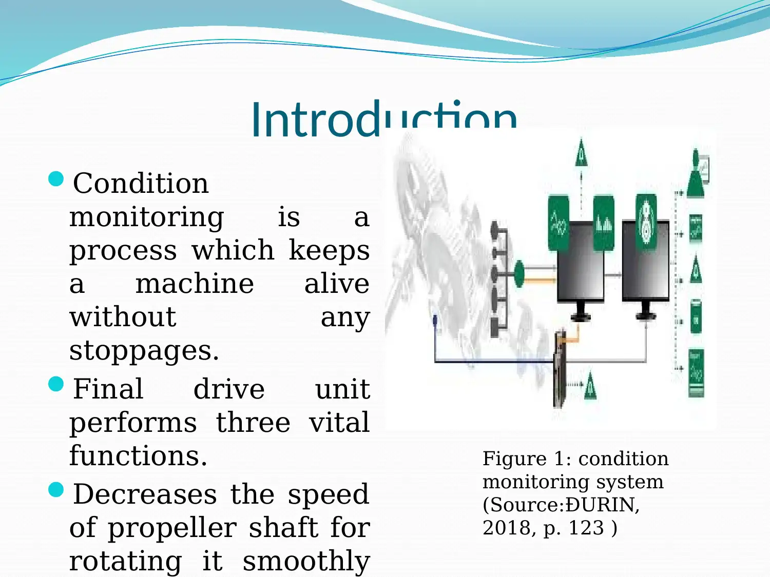
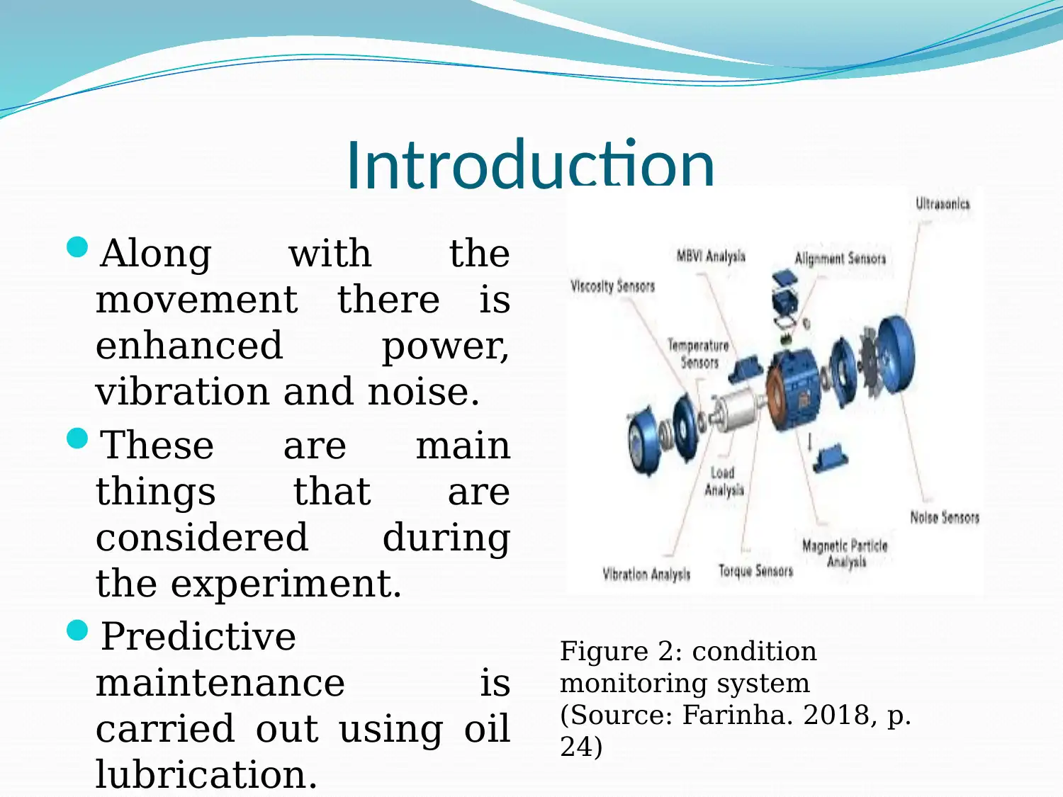
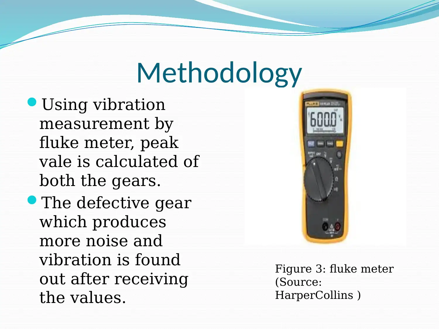
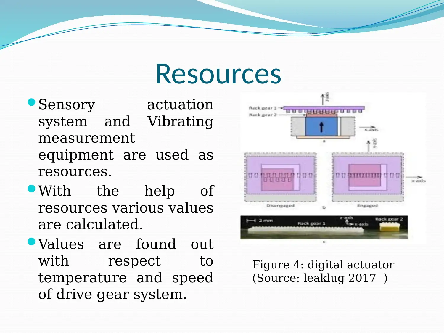
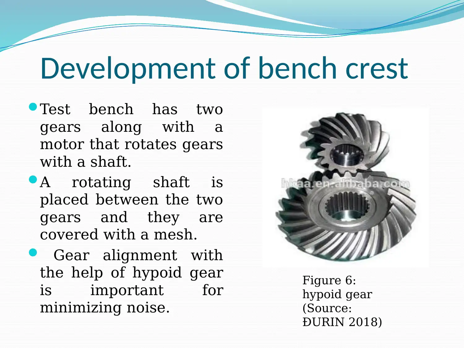
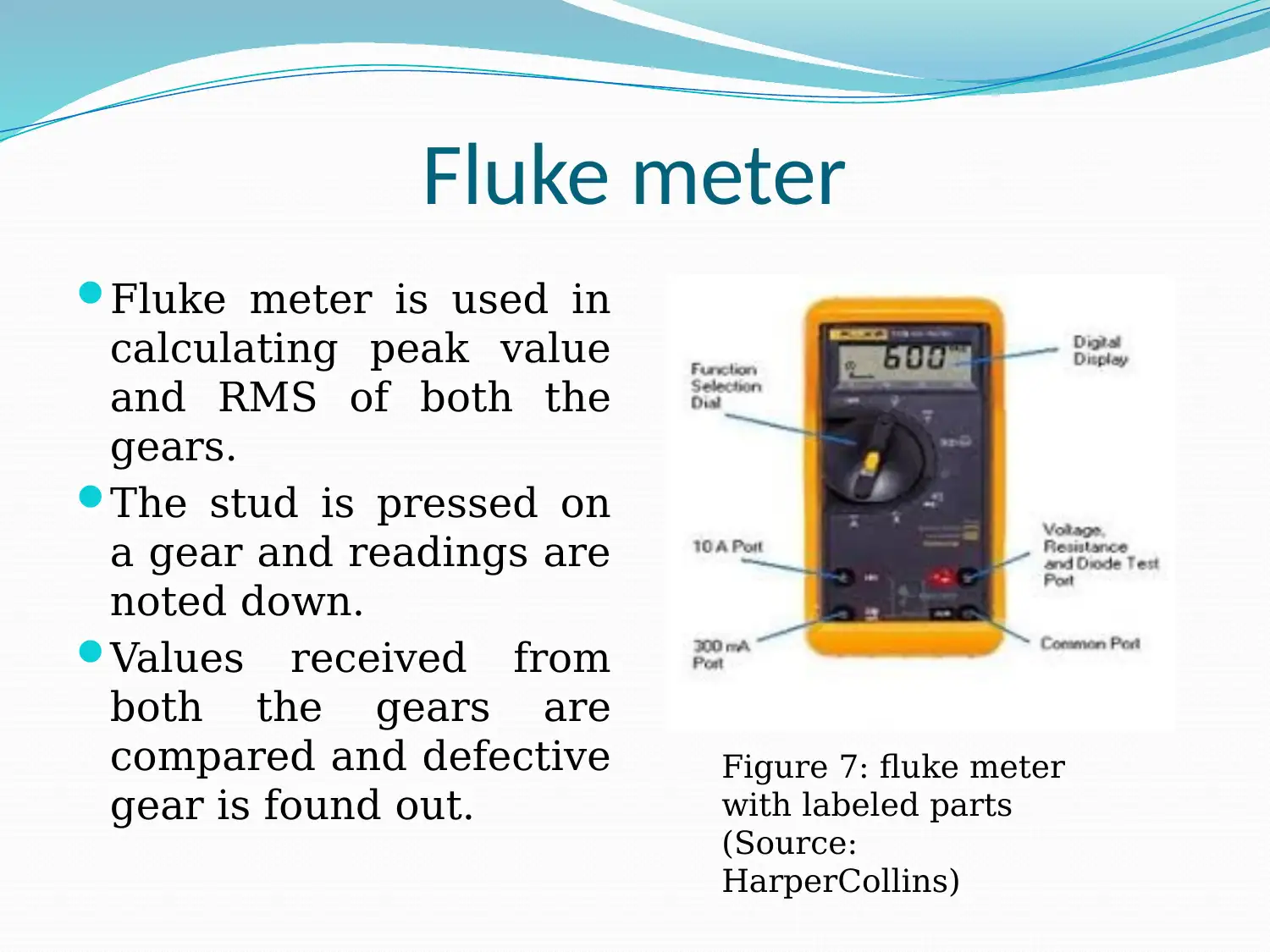
This case study focuses on condition monitoring of an automotive final drive using vibration analysis. The aim is to develop a specific action and technique for monitoring the final drive's condition, locate wear debris with lubricating oil, identify defective gears using sensors, and rectify problems using condition monitoring techniques. The methodology involves assessing gear meshing to avoid noise, checking sensory actuation systems, and repeating experiments at different temperatures and speeds. Resources include sensory actuation, vibrating systems, and measurement equipment. A test bench with gears, a motor, and a rotating shaft is used, with gear alignment being crucial for minimizing noise. A Fluke meter is used to calculate peak and RMS values, and vibration analysis is performed to identify defective gears. Practical experimental analysis involves running the motor, observing parameters like noise, vibration, and temperature, and using the Fluke meter for vibration analysis. Recorded values for both gears at different RPMs are presented, and results indicate changes in peak value with increased speed and temperature. The study concludes with the importance of maintenance activities and provides relevant references.
Document Page
CONDITION MONITORING OF AN
AUTOMOTIVE FINAL DRIVE
tabler-icon-diamond-filled.svg

Paraphrase This Document

Need a fresh take? Get an instant paraphrase of this document with our AI Paraphraser
Document Page
Outline
Aims
Objectives
Introduction
Methodology
Resources
Development of bench crest
Vibration analysis
Practical experimental analysis
Recorded values
Outcomes
Document Page
Aims
To develop a specific action condition
To develop a specific technique for condition
monitoring of an automotive final drive.
To locate wear debris with the help of
lubricating oil.
To find defective gear from equipments with
the help of sensors.
To rectify the problems with the help of a
technique for condition monitoring.
Document Page
Objectives
To check if the two gear derives are meshed
with each other or not for avoiding the noise
produced during the time of vibration.
To check the active participation of sensory
actuation system.
The experiments would be repeated using
different values of temperature and speed, for
getting accurate outcomes in regular
intervals.
tabler-icon-diamond-filled.svg

Paraphrase This Document

Need a fresh take? Get an instant paraphrase of this document with our AI Paraphraser
Document Page
Introduction
Condition
monitoring is a
process which keeps
a machine alive
without any
stoppages.
Final drive unit
performs three vital
functions.
Decreases the speed
of propeller shaft for
rotating it smoothly
Figure 1: condition
monitoring system
(Source:ĐURIN,
2018, p. 123 )
Document Page
Introduction
Along with the
movement there is
enhanced power,
vibration and noise.
These are main
things that are
considered during
the experiment.
Predictive
maintenance is
carried out using oil
lubrication.
Figure 2: condition
monitoring system
(Source: Farinha. 2018, p.
24)
Document Page
Methodology
Obtaining smooth movement of gears with
the help of identified defective gear by the
vibration movement.
Vibration defects the gear and might provide
danger regarding mesh ups weariness
structure, uneven surface and many more.
Peak value is calculated, peak to peak value
depicts the maximum value.
Peak and peak to peak value is defined as
Vp= vpp2
tabler-icon-diamond-filled.svg

Paraphrase This Document

Need a fresh take? Get an instant paraphrase of this document with our AI Paraphraser
Document Page
Methodology
Using vibration
measurement by
fluke meter, peak
vale is calculated of
both the gears.
The defective gear
which produces
more noise and
vibration is found
out after receiving
the values.
Figure 3: fluke meter
(Source:
HarperCollins )
Document Page
Resources
Sensory actuation
system and Vibrating
measurement
equipment are used as
resources.
With the help of
resources various values
are calculated.
Values are found out
with respect to
temperature and speed
of drive gear system.
Figure 4: digital actuator
(Source: leaklug 2017 )
Document Page
Resources
Values are found out
with respect to
temperature and
speed of drive gear
system.
Various articles as
well as journals are
used for the
practice. Figure 5:
actuator
(Source:
Mohammadpour
2013)
tabler-icon-diamond-filled.svg

Paraphrase This Document

Need a fresh take? Get an instant paraphrase of this document with our AI Paraphraser
Document Page
Development of bench crest
Test bench has two
gears along with a
motor that rotates gears
with a shaft.
A rotating shaft is
placed between the two
gears and they are
covered with a mesh.
Gear alignment with
the help of hypoid gear
is important for
minimizing noise.
Figure 6:
hypoid gear
(Source:
ĐURIN 2018)
Document Page
Fluke meter
Fluke meter is used in
calculating peak value
and RMS of both the
gears.
The stud is pressed on
a gear and readings are
noted down.
Values received from
both the gears are
compared and defective
gear is found out.
Figure 7: fluke meter
with labeled parts
(Source:
HarperCollins)
chevron_up_icon
1 out of 22
circle_padding
hide_on_mobile
zoom_out_icon
[object Object]