Use Case Model Diagram (Logical Design Diagram) | Report
27 Pages6046 Words161 Views
Added on 2019-09-26
Use Case Model Diagram (Logical Design Diagram) | Report
Added on 2019-09-26
ShareRelated Documents
1

Contents1.Use Case Model Diagram (Logical Design Diagram)..................................................................42.Class Diagram (Logical Design)..................................................................................................63.Sequence Diagram (Logical Design)............................................................................................84. Program........................................................................................................................................9Critical Discussion: Introduction...................................................................................................18NationNarrow Reflection and Critical-Evaluation....................................................................18Critical self-reflection on the work................................................................................................19Software Development Life Cycle (SDLC) of this software.....................................................19Requirement Gathering..........................................................................................................19Design.....................................................................................................................................19Development..........................................................................................................................20Software Testing.....................................................................................................................20Deployment............................................................................................................................21Feedback.................................................................................................................................22Issues..............................................................................................................................................23Conclusion.....................................................................................................................................23References......................................................................................................................................242
Table of ContentS. NO.CONTENTPAGE NO.1.Use Case Model Diagram22.Class Diagram43.Sequence Diagram64.Program85.Critical Discussion : Introduction166.Critical self-reflection on the work177.Issues218.Conclusion 219.References223
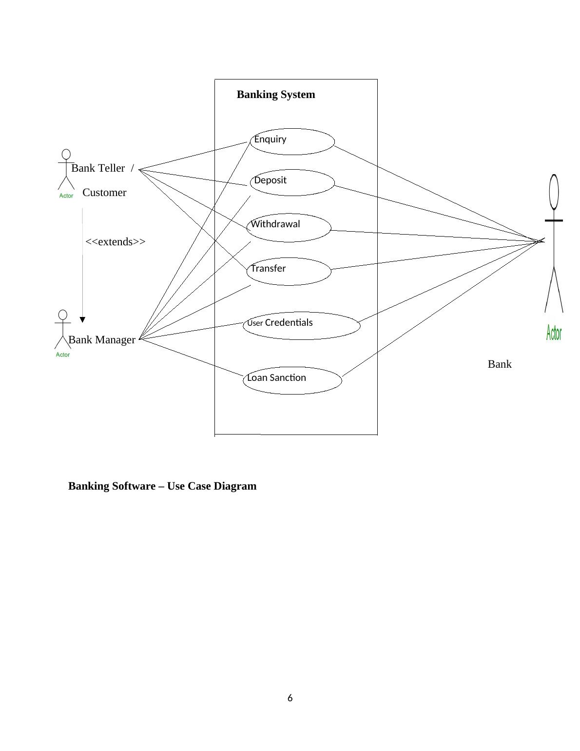
1.Use Case Model Diagram (Logical Design Diagram)This diagram is employed to characterize different actors / users or clients and theiroperations or actions or events. This use case diagram is employed to model the structure ofsoftware or a sub system. It highlights the representation of user and their actions in whichthe particular user or an actor or a client is working on. It has mainly 2 components one isactor and two is use case in a specific application It specifies the users who are all going touse particular software without minding the actual implementation of a function. The actorsare the real end users of the software which is depicted using an actor stereotype. The usecase action is specified using oval symbol. It is to be named with an action verb forfunctionality. The relationship between actor and a use case symbol is depicted through aline which linkages the both. In this Banking Software for NatioNarrow Building Society 3main use cases where defined. They are oBank Manager, oBank Teller and Customer.The Bank Teller and the customer acts on account creation with enquiry of bankstatements, deposit functionality, withdrawal action and fund transfer activities. The Bankmanager acts on the above work flow along with adding user credentials and dealing withapproving and sanctioning of loans and allows to create account on various categories includingcurrent, saving, ISA, Business, etc., The Bank manager use case inherits all the properties of theuse case bank teller and also in terms of customer point of view.4
Bank Software - Use Case Diagram ExplanationThe following Bank Software Use Case diagram is a diagrammatic representation ofdifferent use cases or actors or users of this particular software. e.g. the bank teller may be oneactor, customer is an another actor and bank manager is an one more actor of this software. Thebank teller actor performs actions such as balance enquiry, cash deposit, cash withdrawal andfund transfer operations in this bank software. Like bank teller actor, customer actor alsoperforms operations like enquiry, deposit, withdrawal and transfer operations in this banksoftware. The bank manager actor performing operation includes user credential and loanapproval and sanctioning along with balance enquiry, cash deposit, cash withdrawal and fundtransfer operations in this bank software. The Banking System is a software system which includes the key operations played bythe actors Bank teller, Customer and Bank Manager. The operations of Banking Software are keyfunctionality of the software which includes balance amount enquiry, cash deposit, cashwithdrawal and fund operations, making user credentials, loan sanctioning in this bank software.The actor on the right hand side is a bank use case or actor. It represents the complete operationsdone on behalf of bank software. The Bank Software operations are affected on the actor bank 5
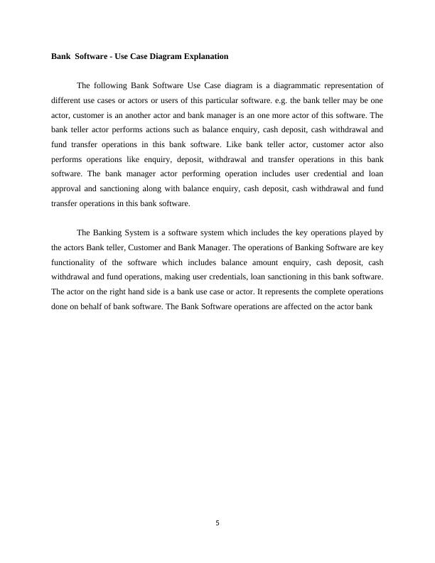
Banking System Bank Teller / Customer <<extends>>Bank Manager BankBanking Software – Use Case Diagram6EnquiryDepositWithdrawalTransferUser CredentialsLoan Sanction
End of preview
Want to access all the pages? Upload your documents or become a member.
Related Documents
Use Case Model Diagram (Logical Design Diagram) | Assignmentlg...
|28
|6017
|505
Logical Design Diagram (Doc)lg...
|27
|5971
|154
Use Case Model Diagram (Logical Design Diagram) Assignmentlg...
|27
|5261
|344
Desklib - Online Library for Study Material with Solved Assignments, Essays, Dissertationslg...
|28
|5911
|302
Case Model Diagramlg...
|26
|5411
|298
ATM System Modelling: Sequence Diagram for Transaction Subsystemlg...
|18
|3089
|466