Analysis of Amplifiers in Control Systems Assignment
VerifiedAdded on 2023/01/18
|5
|473
|66
Homework Assignment
AI Summary
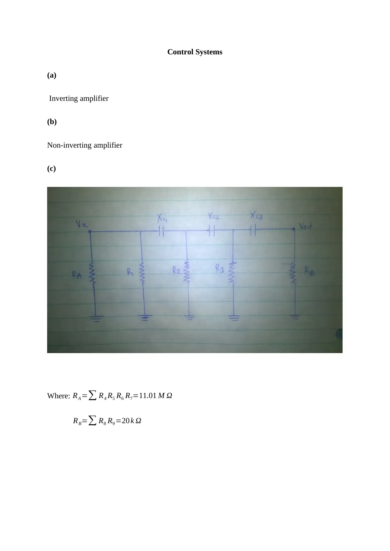
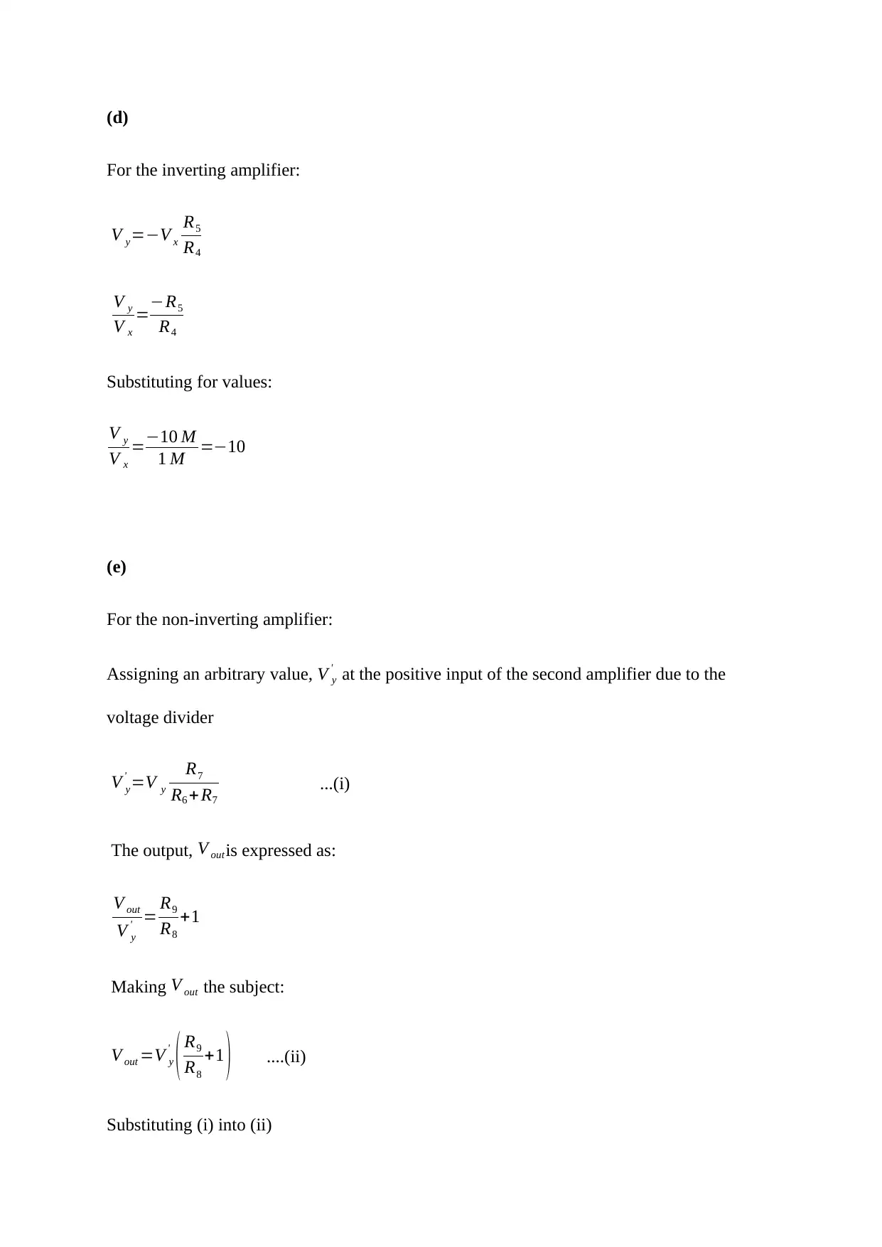
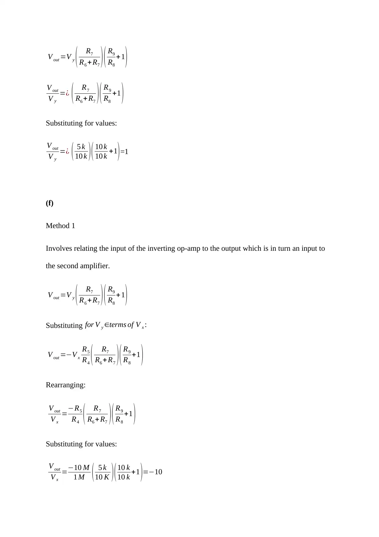
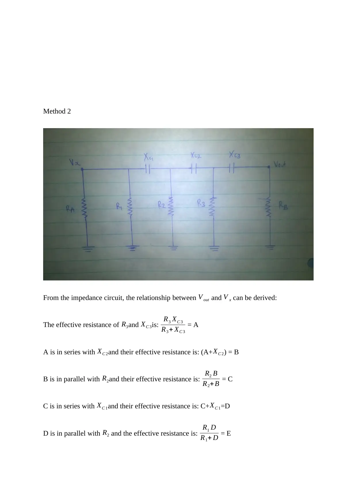
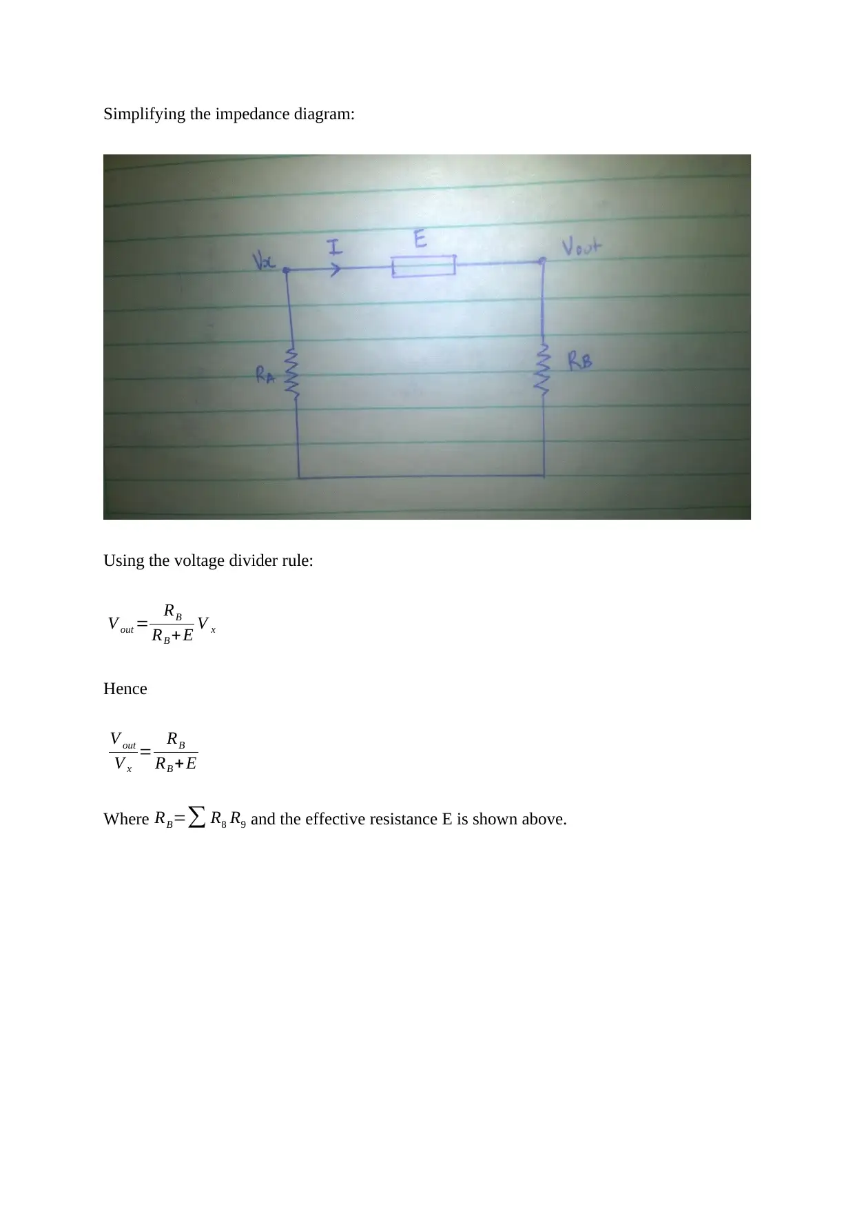
This assignment solution focuses on the analysis of inverting and non-inverting amplifiers within a Control Systems context. The solution begins by defining the components and parameters of the circuit, including resistor values and relationships. It then proceeds to derive the output voltage equations for both inverting and non-inverting amplifier configurations, using the voltage divider rule and other relevant circuit analysis techniques. The solution also provides two methods for relating the input and output voltages, and the impedance circuit and the effective resistance of various components are also considered. The document uses mathematical expressions and substitutions to analyze the behavior of the amplifiers, providing a comprehensive understanding of their functionality within the control system.
1 out of 5



![[object Object]](/_next/static/media/star-bottom.7253800d.svg)