Investigating Coulomb's Law: A Physics Experiment Report
VerifiedAdded on 2023/05/27
|15
|3266
|101
Report
AI Summary
This report details a physics experiment designed to verify Coulomb's Law using a PASCO Model ES-9070 Coulomb balance. The experiment investigated the relationship between the torsion wire's twist angle and the separation distance between charged spheres, demonstrating an inverse square relationship. The study also examined the proportionality between the force generated and the twist angle. The experiment yielded values for εo and the Coulomb constant (k), with percentage differences of 10.2% and 7.3% respectively, when compared to theoretical values, thus validating Coulomb's Law. The report includes the experimental setup, methods employed to measure force versus distance and the torsion constant, the results obtained from two methods, and a discussion of the findings, concluding with an analysis of the experiment's success in confirming Coulomb's Law.
Coulomb’s Law Experiment 1
COULOMB’S LAW EXPERIMENT
Name
Course
Professor
University
City/state
Date
COULOMB’S LAW EXPERIMENT
Name
Course
Professor
University
City/state
Date
Paraphrase This Document
Need a fresh take? Get an instant paraphrase of this document with our AI Paraphraser
Coulomb’s Law Experiment 2
Abstract
The main purpose of this experiment was to investigate and verify Coulomb’s law. PASCO
Model ES-9070 Coulomb balance was used to collect relevant data. Findings from the
experiment showed that the angle through which the torsion wire twisted was directly
proportional to the inverse of square of separation distance between the two spheres. Another
finding was that the force created between the spheres was directly proportional to the twisted
angle. The values of εo and Coulomb constant, k, obtained from the experiment were 9.76 x 10⁻¹²
C2/Nm2 and 8.33 x 10⁹ Nm2/C2 respectively. The percentage difference between theoretical and
experimental value of εo was 10.2% while that for Coulomb constant was 7.3%. Therefore this
experiment verified Coulomb’s law.
Coulomb’s Law Experiment 3
Table of Contents
Abstract......................................................................................................................................................2
1. Introduction.......................................................................................................................................4
2. Methods..............................................................................................................................................5
2.1. Force vs. distance.......................................................................................................................5
2.2. Measuring the torsion constant Ktor..........................................................................................7
3. Results................................................................................................................................................8
3.1. Experiment 1..............................................................................................................................8
3.1.1. Method 1:.............................................................................................................................8
3.1.2. Method 2:.............................................................................................................................9
3.2. Experiment 2............................................................................................................................10
3.3. Calculation of Coulomb constant...........................................................................................11
4. Discussion.........................................................................................................................................13
5. Conclusions......................................................................................................................................14
References................................................................................................................................................15
⊘ This is a preview!⊘
Do you want full access?
Subscribe today to unlock all pages.

Trusted by 1+ million students worldwide
Coulomb’s Law Experiment 4
1. Introduction
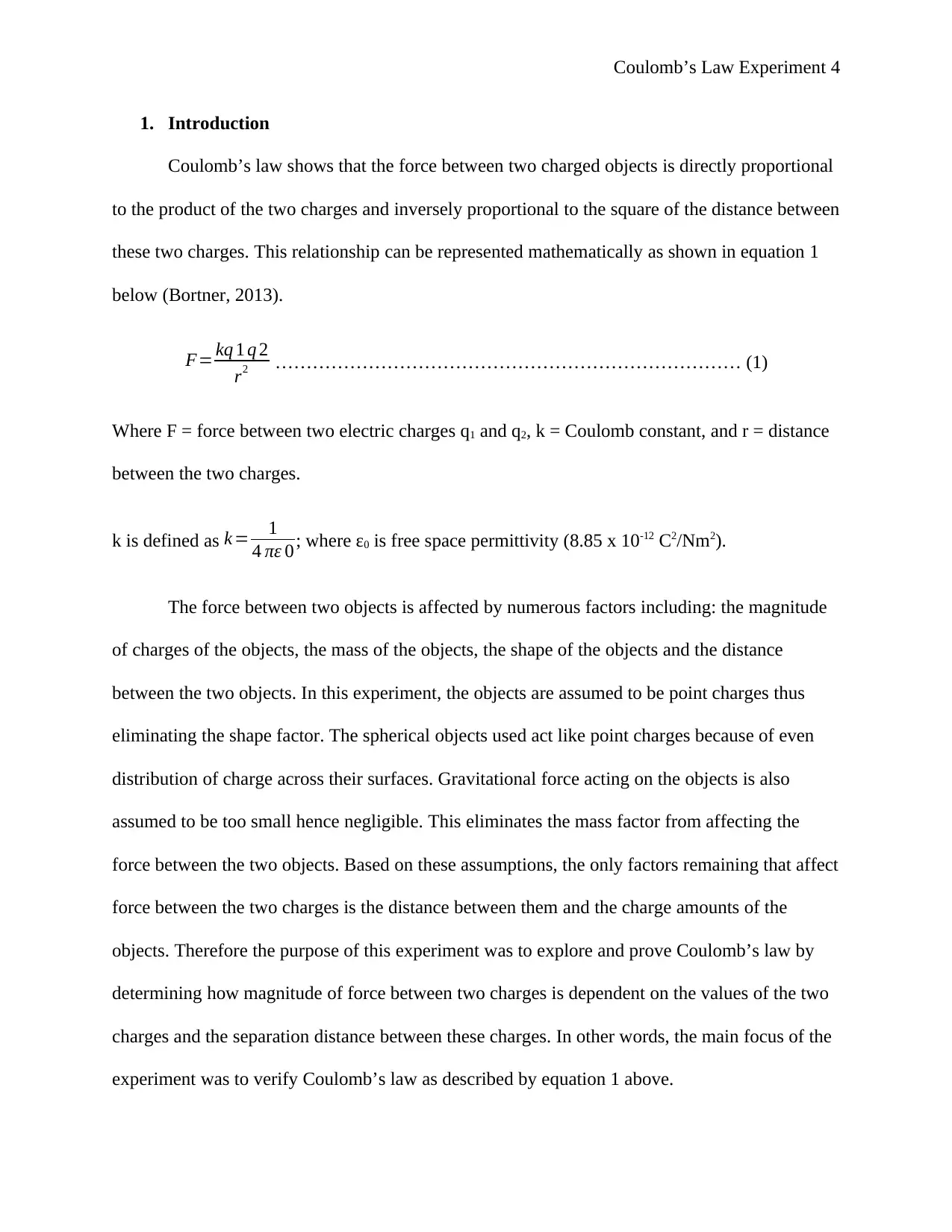
Coulomb’s law shows that the force between two charged objects is directly proportional
to the product of the two charges and inversely proportional to the square of the distance between
these two charges. This relationship can be represented mathematically as shown in equation 1
below (Bortner, 2013).
F= kq 1 q 2
r2 ………………………………………………………………… (1)
Where F = force between two electric charges q1 and q2, k = Coulomb constant, and r = distance
between the two charges.
k is defined as k = 1
4 πε 0; where ε0 is free space permittivity (8.85 x 10⁻¹² C2/Nm2).
The force between two objects is affected by numerous factors including: the magnitude
of charges of the objects, the mass of the objects, the shape of the objects and the distance
between the two objects. In this experiment, the objects are assumed to be point charges thus
eliminating the shape factor. The spherical objects used act like point charges because of even
distribution of charge across their surfaces. Gravitational force acting on the objects is also
assumed to be too small hence negligible. This eliminates the mass factor from affecting the
force between the two objects. Based on these assumptions, the only factors remaining that affect
force between the two charges is the distance between them and the charge amounts of the
objects. Therefore the purpose of this experiment was to explore and prove Coulomb’s law by
determining how magnitude of force between two charges is dependent on the values of the two
charges and the separation distance between these charges. In other words, the main focus of the
experiment was to verify Coulomb’s law as described by equation 1 above.
Paraphrase This Document
Need a fresh take? Get an instant paraphrase of this document with our AI Paraphraser
Coulomb’s Law Experiment 5
It is very difficult to keep many charges of equal polarity close to each other for some
time hence the objects used in this experiment are of small quantities of charge. This implies that
the force between these two charges is very small hence it can only be measured using a tiny
scale. In this experiment, a delicate torsion balance can be used to determine the force between
the two charges where force is proportional to the extent over which the wire of the torsion
balance twists rather than the extension of the spring. According to Hooke’s law, the angle by
which a wire twists from the equilibrium is proportional to the force as shown in equation 2
below
F = Kθ ………………………………………………………………. (2)
Where K = torsion constant and θ = angle twisted angle from the equilibrium.
To perform this experiment, the two objects/spheres should be charged the placed at a
separation distance. The two spheres produce an electrostatic repulsion that causes the wire of
the torsion balance to twist. The twist angle of the torsion wire is proportional to the force acting
between these two spheres. The two spheres are charged using a power supply that provides a
steady voltage. It is also worth noting that the quantity of charge deposited in the sphere is
proportional to the voltage as shown in equation 3 below
q = CV ……………………………………………………………. (3)
Where q = charge, C = capacitance (proportionality constant) and V = voltage
2. Methods
2.1. Force vs. distance
The apparatus used to perform the experiment were Pasco Model ES-9070 Coulomb
balance and a 6kV power supply fixed with a charging probe. This model is very precise and
Coulomb’s Law Experiment 6
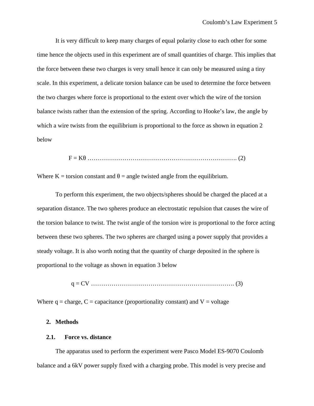
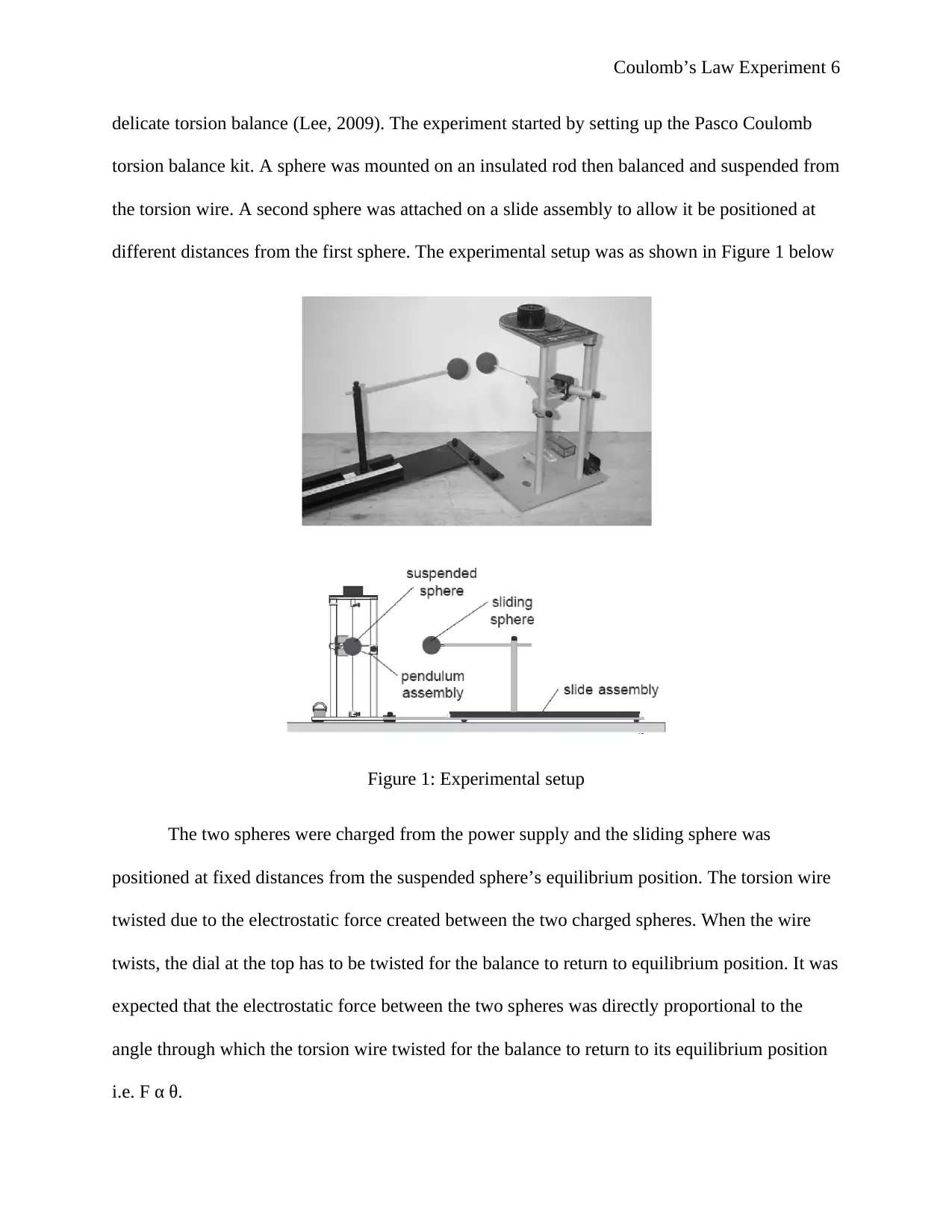
delicate torsion balance (Lee, 2009). The experiment started by setting up the Pasco Coulomb
torsion balance kit. A sphere was mounted on an insulated rod then balanced and suspended from
the torsion wire. A second sphere was attached on a slide assembly to allow it be positioned at
different distances from the first sphere. The experimental setup was as shown in Figure 1 below
Figure 1: Experimental setup
The two spheres were charged from the power supply and the sliding sphere was
positioned at fixed distances from the suspended sphere’s equilibrium position. The torsion wire
twisted due to the electrostatic force created between the two charged spheres. When the wire
twists, the dial at the top has to be twisted for the balance to return to equilibrium position. It was
expected that the electrostatic force between the two spheres was directly proportional to the
angle through which the torsion wire twisted for the balance to return to its equilibrium position
i.e. F α θ.
⊘ This is a preview!⊘
Do you want full access?
Subscribe today to unlock all pages.

Trusted by 1+ million students worldwide
Coulomb’s Law Experiment 7
After setting up the torsion balance, which was placed on a conducting mat on the floor
where the experimenter would touch to ensure that he carried no significant charge, the sliding
sphere was moved from the suspended sphere to the maximum separation distance. The torsion
dial was set to 0°. The torsion balance was zeroed then one terminal of the 1kV power supply
was connected to the red charging probe and the other terminal was connected to the mat. The
kV power supply was switched on then the dial was turned to 6 kV. Both spheres were charged
by touching each one of them with the charging probe to a potential voltage of 6 kV. The sliding
sphere was positioned at a separation distance of 20 cm then the torsion knob was turned
carefully in an anti-clockwise direction for the forces to balance and for the pendulum to return
to zero position. The resulting angle setting was measured and recorded against the separation
distance. The process was positioning the sliding sphere at a particular distance ® and measuring
the corresponding angle (θ) was repeated at different values of r with charging potential kept
constant at 6 kV.
2.2. Measuring the torsion constant Ktor
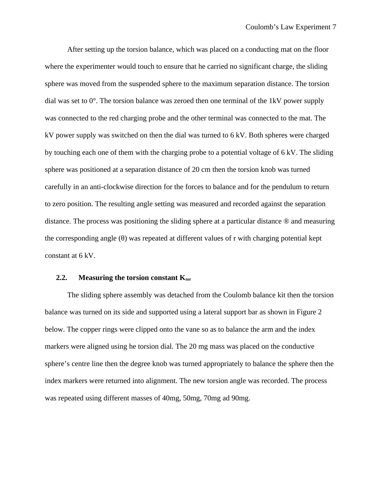
The sliding sphere assembly was detached from the Coulomb balance kit then the torsion
balance was turned on its side and supported using a lateral support bar as shown in Figure 2
below. The copper rings were clipped onto the vane so as to balance the arm and the index
markers were aligned using he torsion dial. The 20 mg mass was placed on the conductive
sphere’s centre line then the degree knob was turned appropriately to balance the sphere then the
index markers were returned into alignment. The new torsion angle was recorded. The process
was repeated using different masses of 40mg, 50mg, 70mg ad 90mg.
Paraphrase This Document
Need a fresh take? Get an instant paraphrase of this document with our AI Paraphraser
Coulomb’s Law Experiment 8
Figure 2: Torsion constant measuring apparatus
3. Results
3.1. Experiment 1
3.1.1. Method 1:
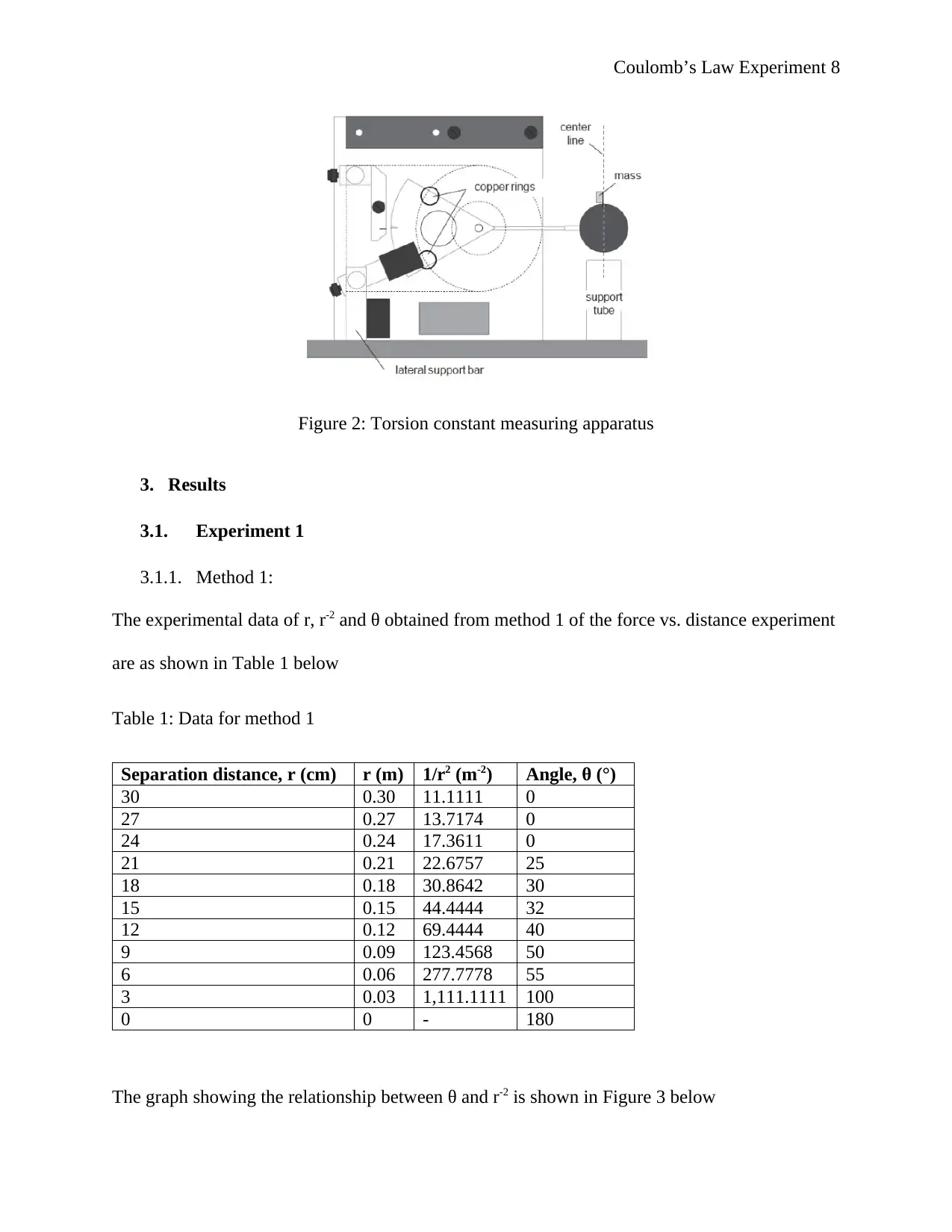
The experimental data of r, r-2 and θ obtained from method 1 of the force vs. distance experiment
are as shown in Table 1 below
Table 1: Data for method 1
Separation distance, r (cm) r (m) 1/r2 (m-2) Angle, θ (°)
30 0.30 11.1111 0
27 0.27 13.7174 0
24 0.24 17.3611 0
21 0.21 22.6757 25
18 0.18 30.8642 30
15 0.15 44.4444 32
12 0.12 69.4444 40
9 0.09 123.4568 50
6 0.06 277.7778 55
3 0.03 1,111.1111 100
0 0 - 180
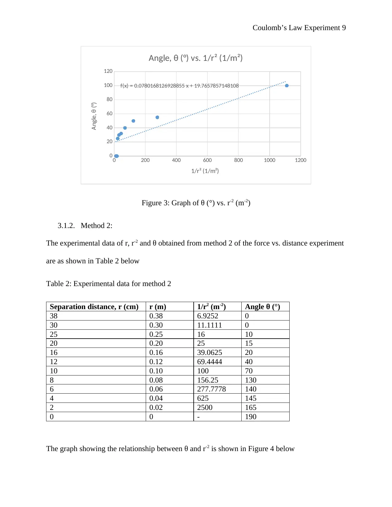
The graph showing the relationship between θ and r-2 is shown in Figure 3 below
Coulomb’s Law Experiment 9
0 200 400 600 800 1000 1200
0
20
40
60
80
100
120
f(x) = 0.0780168126928855 x + 19.7657857148108
Angle, θ (°) vs. 1/r² (1/m²)
1/r² (1/m²)
Angle, θ (°)
Figure 3: Graph of θ (°) vs. r-2 (m-2)
3.1.2. Method 2:
The experimental data of r, r-2 and θ obtained from method 2 of the force vs. distance experiment
are as shown in Table 2 below
Table 2: Experimental data for method 2
Separation distance, r (cm) r (m) 1/r2 (m-2) Angle θ (°)
38 0.38 6.9252 0
30 0.30 11.1111 0
25 0.25 16 10
20 0.20 25 15
16 0.16 39.0625 20
12 0.12 69.4444 40
10 0.10 100 70
8 0.08 156.25 130
6 0.06 277.7778 140
4 0.04 625 145
2 0.02 2500 165
0 0 - 190
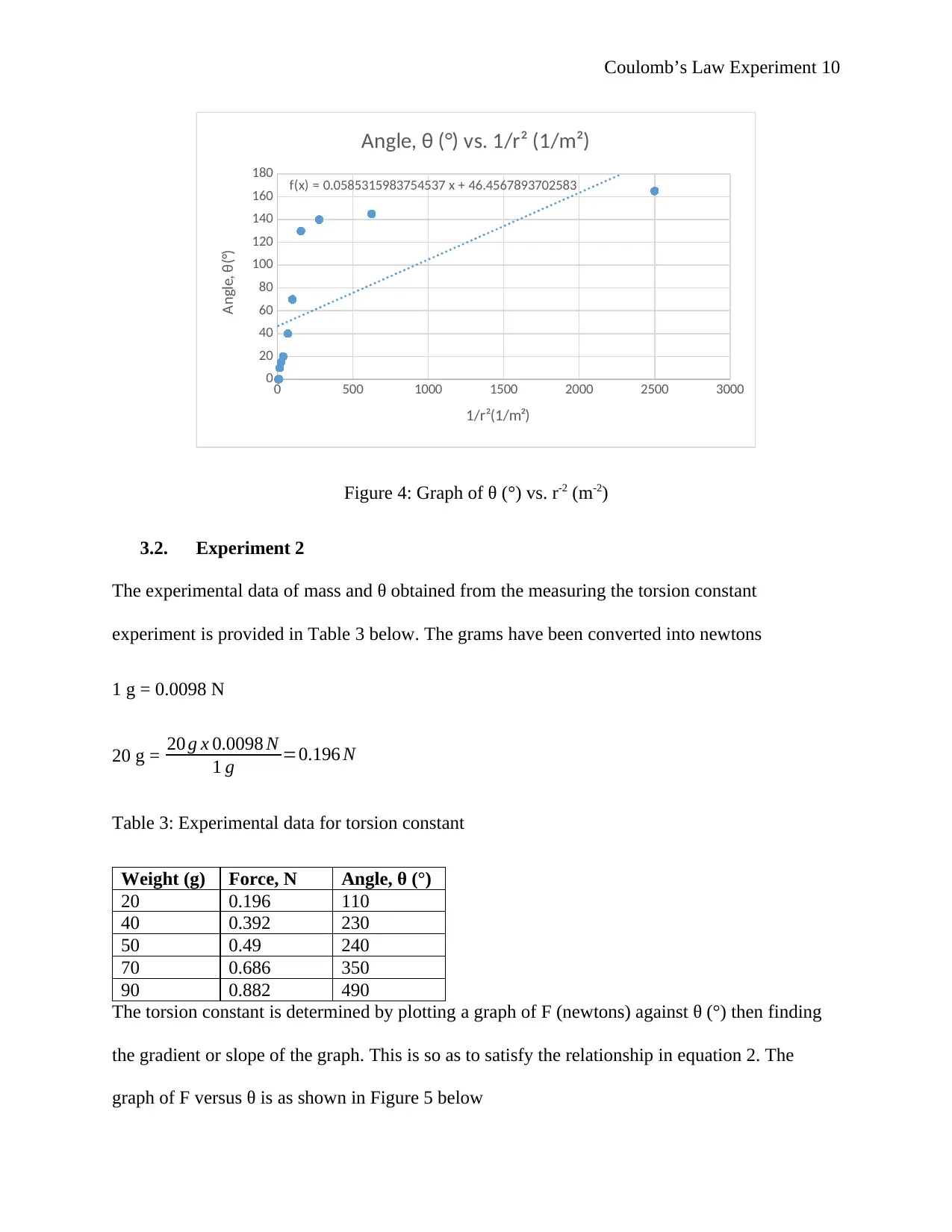
The graph showing the relationship between θ and r-2 is shown in Figure 4 below
⊘ This is a preview!⊘
Do you want full access?
Subscribe today to unlock all pages.

Trusted by 1+ million students worldwide
Coulomb’s Law Experiment 10
0 500 1000 1500 2000 2500 3000
0
20
40
60
80
100
120
140
160
180 f(x) = 0.0585315983754537 x + 46.4567893702583
Angle, θ (°) vs. 1/r² (1/m²)
1/r²(1/m²)
Angle, θ(°)
Figure 4: Graph of θ (°) vs. r-2 (m-2)
3.2. Experiment 2
The experimental data of mass and θ obtained from the measuring the torsion constant
experiment is provided in Table 3 below. The grams have been converted into newtons
1 g = 0.0098 N
20 g = 20 g x 0.0098 N
1 g =0.196 N
Table 3: Experimental data for torsion constant
Weight (g) Force, N Angle, θ (°)
20 0.196 110
40 0.392 230
50 0.49 240
70 0.686 350
90 0.882 490
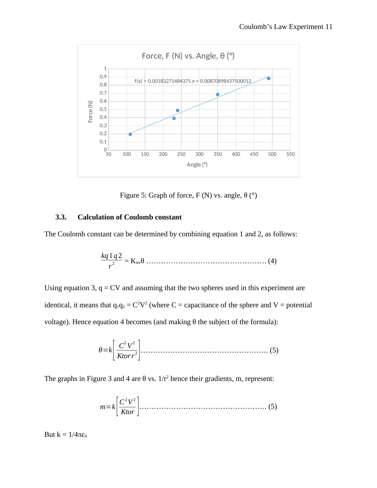
The torsion constant is determined by plotting a graph of F (newtons) against θ (°) then finding
the gradient or slope of the graph. This is so as to satisfy the relationship in equation 2. The
graph of F versus θ is as shown in Figure 5 below
Paraphrase This Document
Need a fresh take? Get an instant paraphrase of this document with our AI Paraphraser
Coulomb’s Law Experiment 11
50 100 150 200 250 300 350 400 450 500 550
0
0.1
0.2
0.3
0.4
0.5
0.6
0.7
0.8
0.9
1
f(x) = 0.00183271484375 x + 0.00870898437500012
Force, F (N) vs. Angle, θ (°)
Angle (°)
Force (N)
Figure 5: Graph of force, F (N) vs. angle, θ (°)
3.3. Calculation of Coulomb constant
The Coulomb constant can be determined by combining equation 1 and 2, as follows:
kq 1 q 2
r 2 = Ktorθ …………………………………………. (4)
Using equation 3, q = CV and assuming that the two spheres used in this experiment are
identical, it means that q1q2 = C2V2 (where C = capacitance of the sphere and V = potential
voltage). Hence equation 4 becomes (and making θ the subject of the formula):
θ=k [ C2 V 2
Ktor r 2 ]……………………………………………. (5)
The graphs in Figure 3 and 4 are θ vs. 1/r2 hence their gradients, m, represent:
m=k [ C2 V 2
Ktor ]……………………………………………. (5)
But k = 1/4πε0
Coulomb’s Law Experiment 12
From Figure 5, the gradient of the line is 0.0018 N/° (Newtons per degree) i.e. Ktor = 0.0018 N/°.
The capacitance of the Pasco Model ES-9070 kit is 2.025 x 10⁻⁸ C/kV
C2V2 = (2.025 x 10⁻⁸ C/kV) x (2.025 x 10⁻⁸ C/kV) x (6 kV) x (6 kV) = 1.476 x 10⁻¹⁴ C2
Thus [ C2 V 2
Ktor ]= 1.476 x 10⁻¹⁴ C2
0.0018 N /° =8.198 x 10⁻¹ 2 C2 ° /N
Using equation 5, m = 8.198 x 10⁻¹² C2°/N x k; k = m
8.198 x 10⁻¹² C2 °/ N
Hence k is determined as follows:
Method 1: m = 0.078 °m2
k = 0.078 ° m ²
8.198 x 10⁻¹² C2 °/ N =9.515 x 10⁹ Nm2 /C2
But k = 1
4 πεo ; ε0 = 1
4 πk = 1
4 π x 9.515 x 109 N m2 /C2 =8 . 36 x 10−12 C2 / N m2
Method 2: m = 0.0585 °m2
k = 0.0585° m ²
8.198 x 10⁻¹² C2 °/ N =7 . 136 x 109 Nm2 /C2
ε0 = 1
4 πk = 1
4 π x 7.136 x 109 N m2 /C2 =1.1152 x 10⁻¹¹ C2 / N m2
The average values of k and ε0 are as follows:
k = 9.515 x 10⁹ +7 . 136 x 109
2 =8.33 x 10⁹ N m2 /C2
ε0 = 8.36 x 10⁻¹ 2 +1. 1152 x 10−11
2 =9 .75 6 x 10⁻¹² C2 / N m2
⊘ This is a preview!⊘
Do you want full access?
Subscribe today to unlock all pages.

Trusted by 1+ million students worldwide
Coulomb’s Law Experiment 13
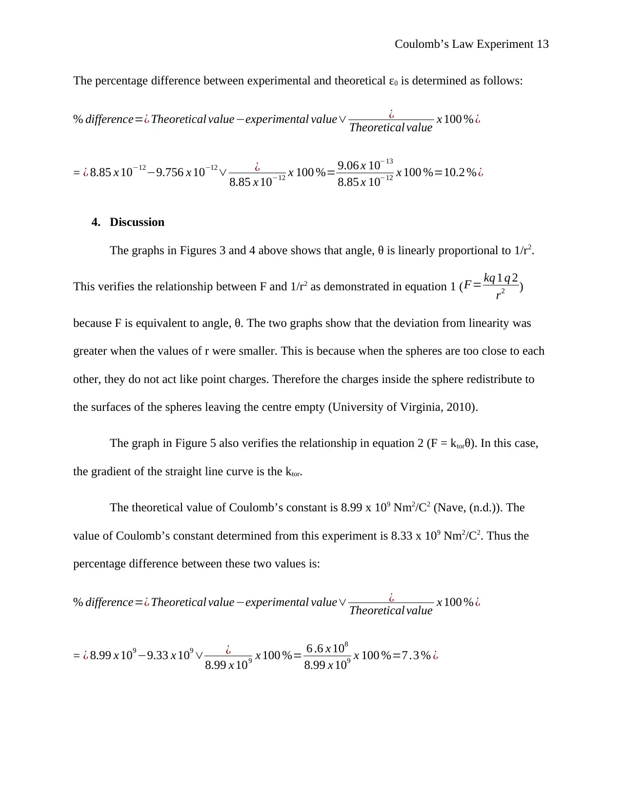
The percentage difference between experimental and theoretical ε0 is determined as follows:
% difference=¿ Theoretical value−experimental value∨ ¿
Theoretical value x 100 % ¿
= ¿ 8.85 x 10⁻¹²−9.756 x 10⁻¹²∨ ¿
8.85 x 10−12 x 100 %= 9.06 x 10⁻¹³
8.85 x 10−12 x 100 %=10.2 %¿
4. Discussion
The graphs in Figures 3 and 4 above shows that angle, θ is linearly proportional to 1/r2.
This verifies the relationship between F and 1/r2 as demonstrated in equation 1 (F= kq 1 q 2
r2 )
because F is equivalent to angle, θ. The two graphs show that the deviation from linearity was
greater when the values of r were smaller. This is because when the spheres are too close to each
other, they do not act like point charges. Therefore the charges inside the sphere redistribute to
the surfaces of the spheres leaving the centre empty (University of Virginia, 2010).
The graph in Figure 5 also verifies the relationship in equation 2 (F = ktorθ). In this case,
the gradient of the straight line curve is the ktor.
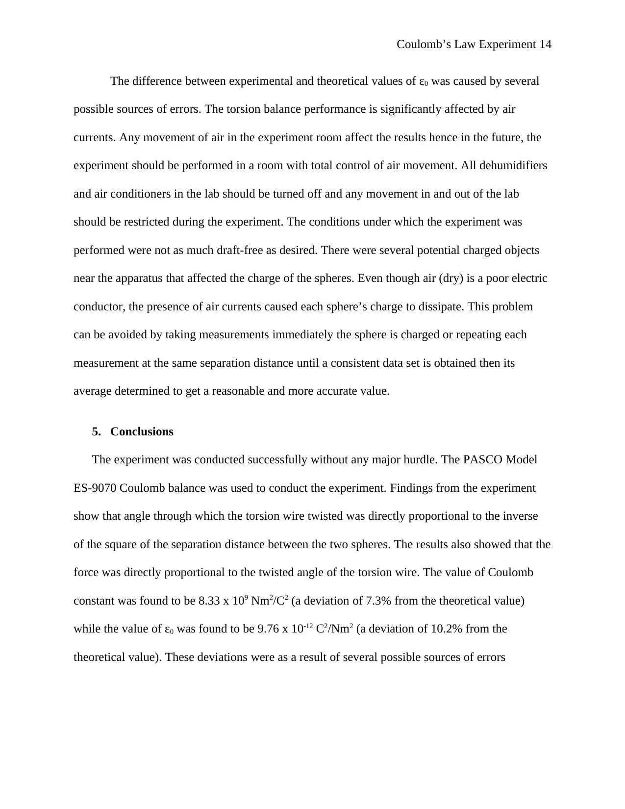
The theoretical value of Coulomb’s constant is 8.99 x 10⁹ Nm2/C2 (Nave, (n.d.)). The
value of Coulomb’s constant determined from this experiment is 8.33 x 10⁹ Nm2/C2. Thus the
percentage difference between these two values is:
% difference=¿ Theoretical value−experimental value∨ ¿
Theoretical value x 100 % ¿
= ¿ 8.99 x 10⁹ −9.33 x 10⁹ ∨ ¿
8.99 x 109 x 100 %= 6 .6 x 108
8.99 x 109 x 100 %=7 .3 % ¿
Paraphrase This Document
Need a fresh take? Get an instant paraphrase of this document with our AI Paraphraser
Coulomb’s Law Experiment 14
The difference between experimental and theoretical values of ε0 was caused by several
possible sources of errors. The torsion balance performance is significantly affected by air
currents. Any movement of air in the experiment room affect the results hence in the future, the
experiment should be performed in a room with total control of air movement. All dehumidifiers
and air conditioners in the lab should be turned off and any movement in and out of the lab
should be restricted during the experiment. The conditions under which the experiment was
performed were not as much draft-free as desired. There were several potential charged objects
near the apparatus that affected the charge of the spheres. Even though air (dry) is a poor electric
conductor, the presence of air currents caused each sphere’s charge to dissipate. This problem
can be avoided by taking measurements immediately the sphere is charged or repeating each
measurement at the same separation distance until a consistent data set is obtained then its
average determined to get a reasonable and more accurate value.
5. Conclusions
The experiment was conducted successfully without any major hurdle. The PASCO Model
ES-9070 Coulomb balance was used to conduct the experiment. Findings from the experiment
show that angle through which the torsion wire twisted was directly proportional to the inverse
of the square of the separation distance between the two spheres. The results also showed that the
force was directly proportional to the twisted angle of the torsion wire. The value of Coulomb
constant was found to be 8.33 x 10⁹ Nm2/C2 (a deviation of 7.3% from the theoretical value)
while the value of ε0 was found to be 9.76 x 10⁻¹² C2/Nm2 (a deviation of 10.2% from the
theoretical value). These deviations were as a result of several possible sources of errors
Coulomb’s Law Experiment 15
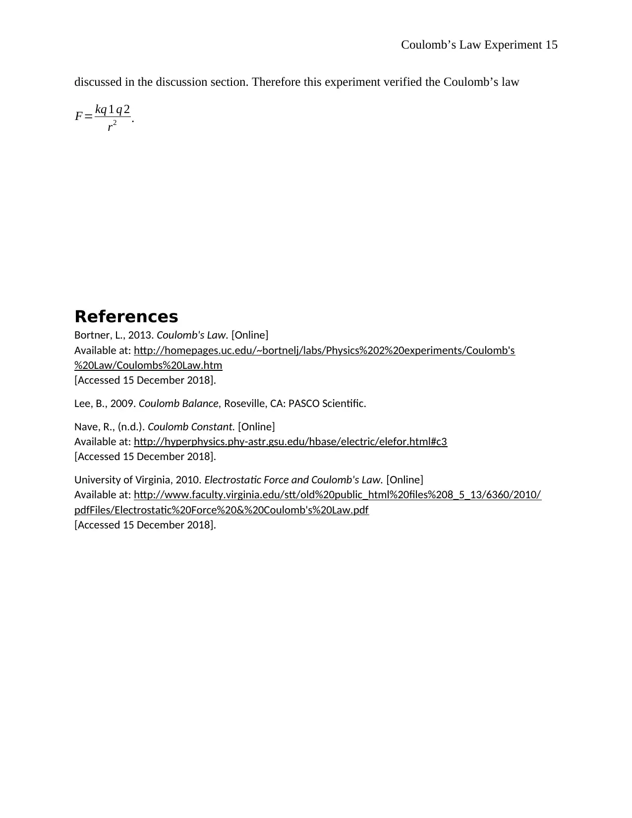
discussed in the discussion section. Therefore this experiment verified the Coulomb’s law
F= kq 1 q 2
r2 .
References
Bortner, L., 2013. Coulomb's Law. [Online]
Available at: http://homepages.uc.edu/~bortnelj/labs/Physics%202%20experiments/Coulomb's
%20Law/Coulombs%20Law.htm
[Accessed 15 December 2018].
Lee, B., 2009. Coulomb Balance, Roseville, CA: PASCO Scientific.
Nave, R., (n.d.). Coulomb Constant. [Online]
Available at: http://hyperphysics.phy-astr.gsu.edu/hbase/electric/elefor.html#c3
[Accessed 15 December 2018].
University of Virginia, 2010. Electrostatic Force and Coulomb's Law. [Online]
Available at: http://www.faculty.virginia.edu/stt/old%20public_html%20files%208_5_13/6360/2010/
pdfFiles/Electrostatic%20Force%20&%20Coulomb's%20Law.pdf
[Accessed 15 December 2018].
⊘ This is a preview!⊘
Do you want full access?
Subscribe today to unlock all pages.

Trusted by 1+ million students worldwide
1 out of 15
Related Documents
Your All-in-One AI-Powered Toolkit for Academic Success.
+13062052269
info@desklib.com
Available 24*7 on WhatsApp / Email
![[object Object]](/_next/static/media/star-bottom.7253800d.svg)
Unlock your academic potential
© 2024 | Zucol Services PVT LTD | All rights reserved.


