HEETCM302 Hydraulics & Pneumatics Lab 1: Component Study Report
VerifiedAdded on 2023/04/11
|9
|899
|280
Practical Assignment
AI Summary
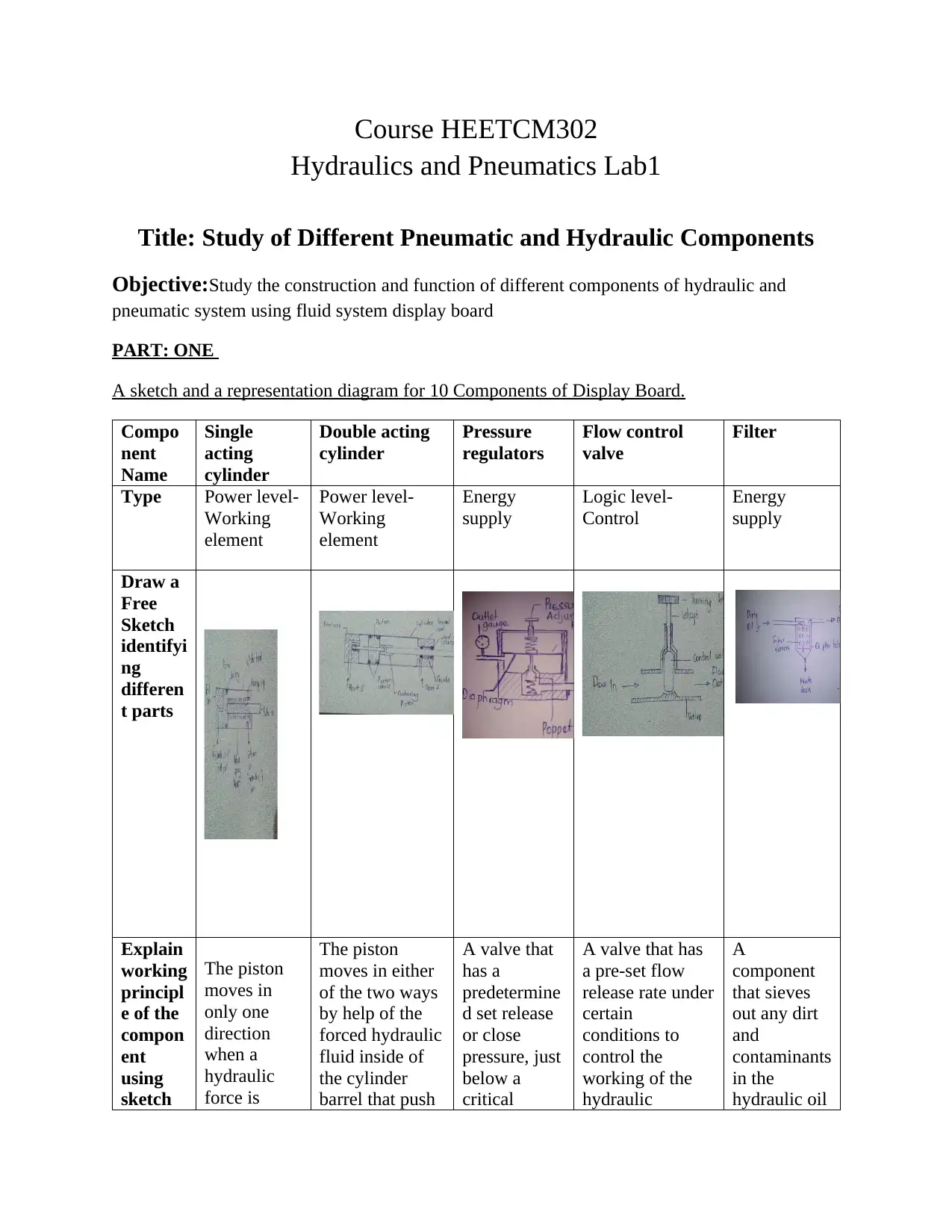
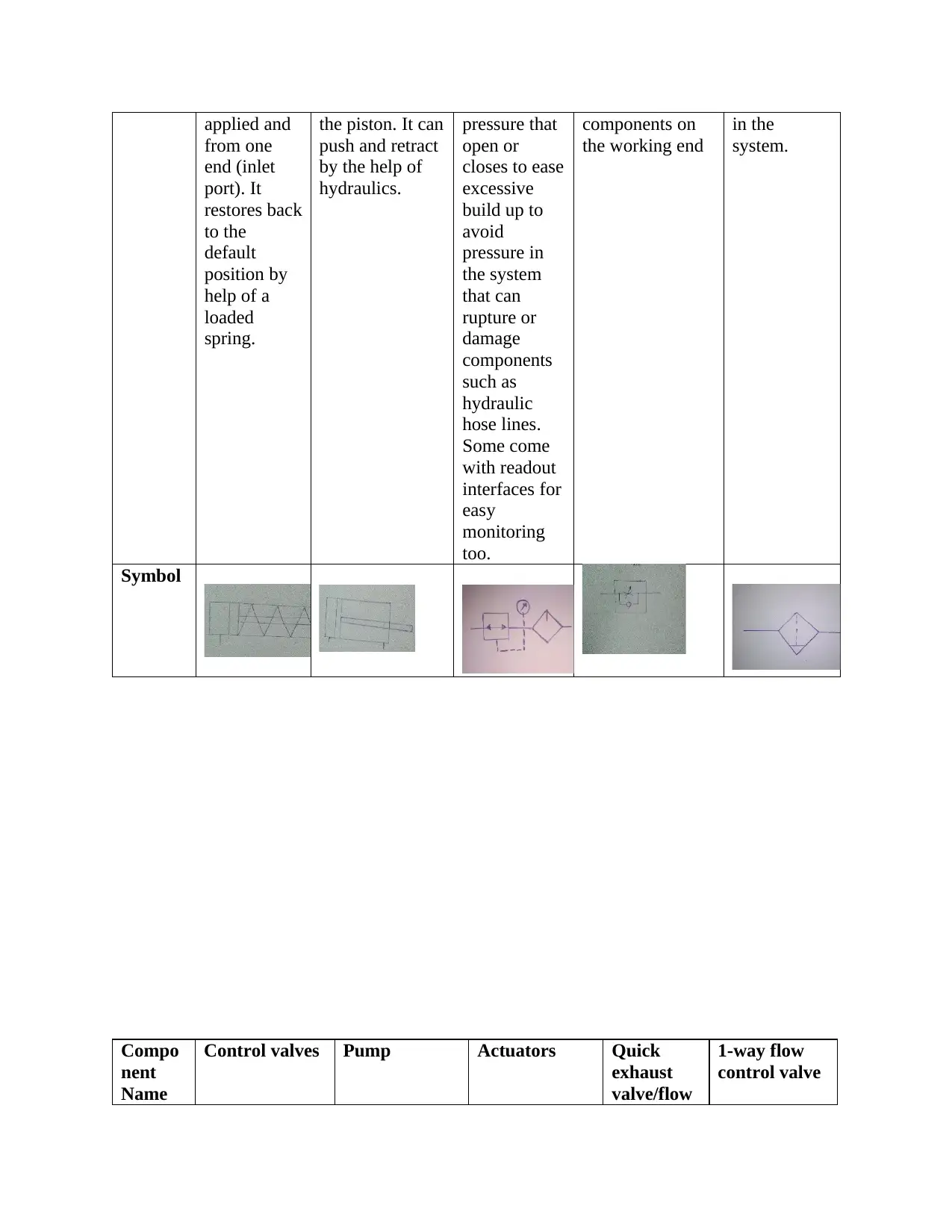
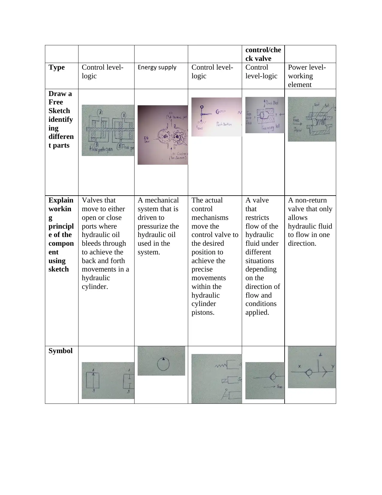
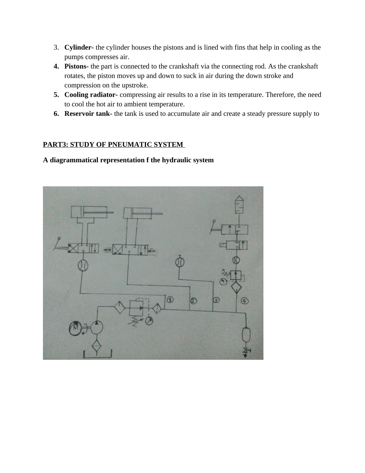
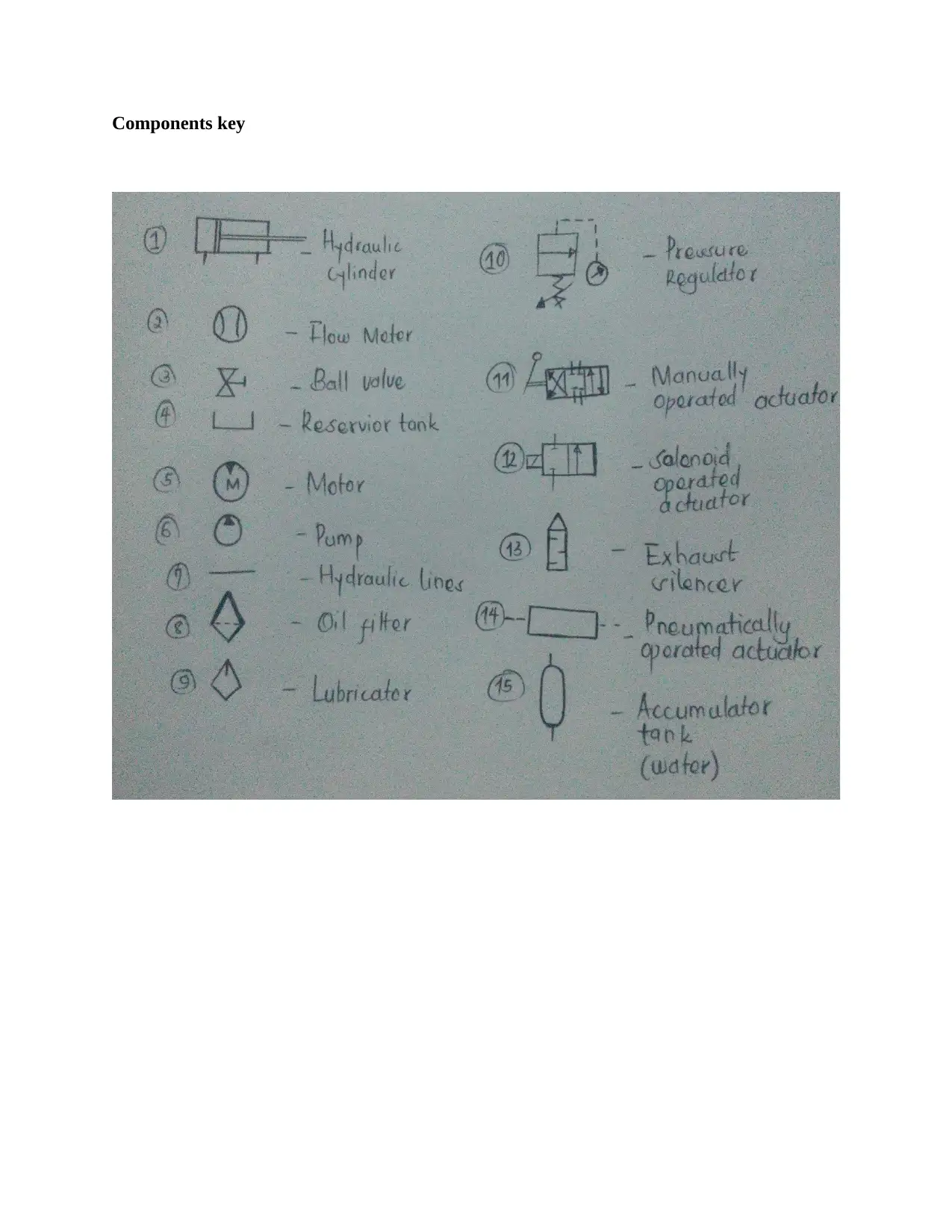
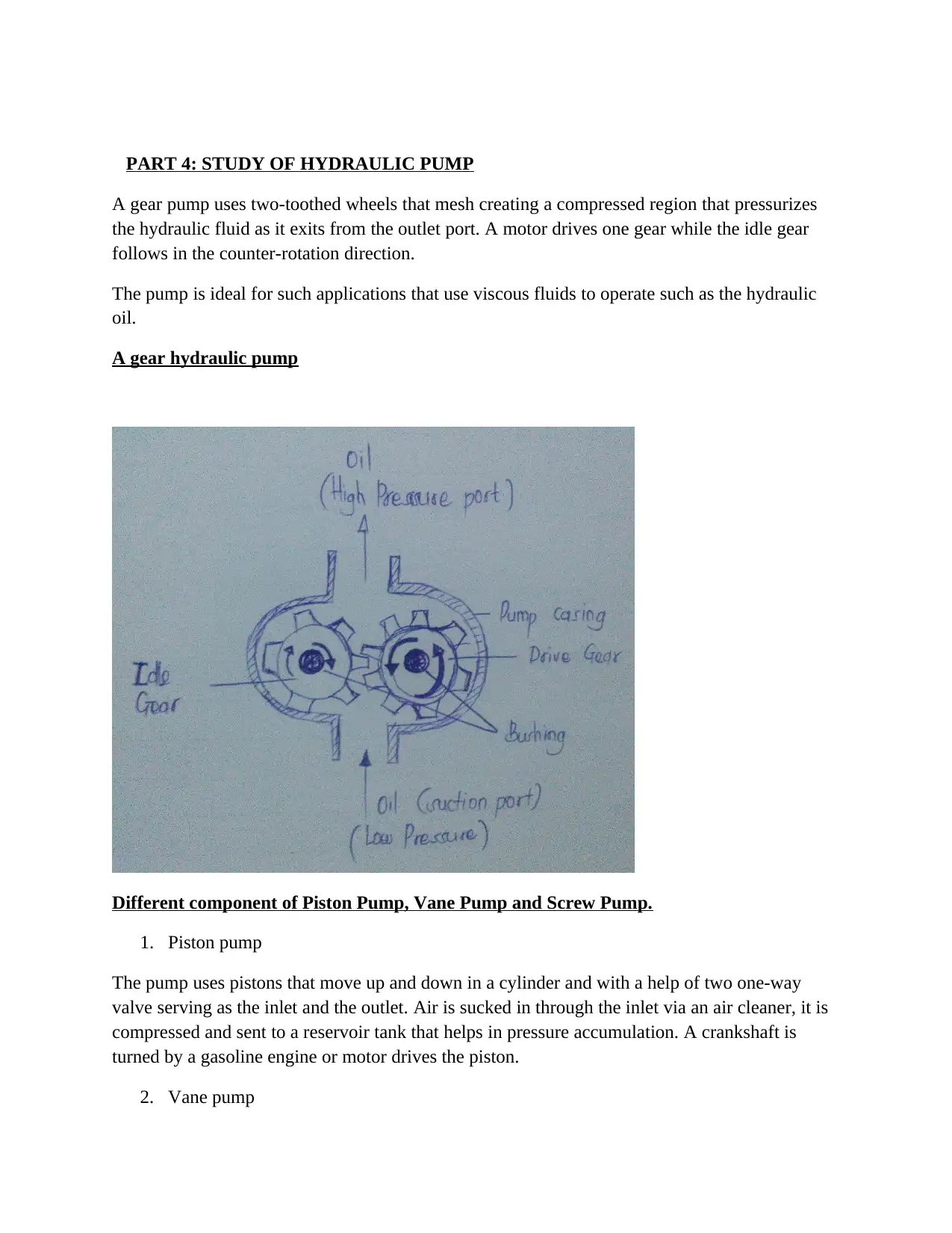
This assignment focuses on the study of various pneumatic and hydraulic components using a fluid system display board. It includes sketches, diagrams, and explanations of components like single and double-acting cylinders, pressure regulators, flow control valves, filters, control valves, and pumps. The study extends to the components of a compressor, detailing the functions of the air cleaner, valves, cylinder, pistons, cooling radiator, and reservoir tank. Furthermore, the pneumatic system is explored with a diagrammatical representation and component identification, followed by an analysis of hydraulic pumps, specifically gear pumps, piston pumps, vane pumps, and screw pumps, highlighting their working mechanisms and components. The assignment also includes the pneumatic system structure with signal flow from bottom to top control chain SPA principle-Sensor, Processor, Actuator and IPO Principle Input, Processing, Output, Energy Supply -Through tubing and Piping.
1 out of 9
Related Documents


Your All-in-One AI-Powered Toolkit for Academic Success.
+13062052269
info@desklib.com
Available 24*7 on WhatsApp / Email
![[object Object]](/_next/static/media/star-bottom.7253800d.svg)
Copyright © 2020–2026 A2Z Services. All Rights Reserved. Developed and managed by ZUCOL.