IMAT5205 Systems Analysis & Design: Modeling Assignment 2 Report

Verified

Added on  2023/04/21

|7
|1887
|199
Report
AI Summary
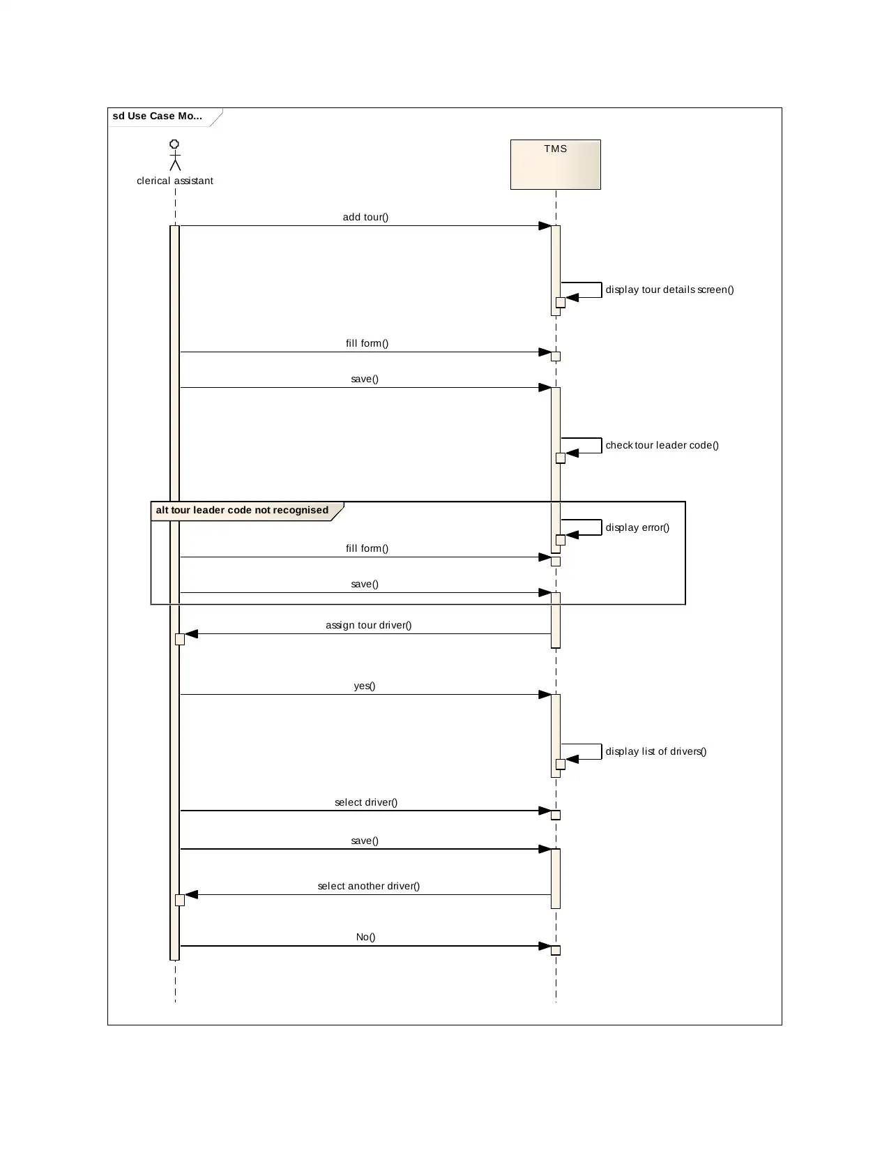
This document presents a student's solution to a Systems Analysis and Design modeling assignment, likely for the course IMAT5205. It includes an analysis class diagram detailing classes, attributes, and relationships within the system, focusing on the 'Record New Tour' use case. The solution also features a communication diagram illustrating interactions between objects during the 'Add New Tour' process, along with a sequence diagram visualizing the flow of actions and messages in the same use case. Decisions made during the modeling process are documented, and the report concludes with an evaluation of CASE tools and their role in software development, referencing the importance of these tools in ensuring software quality and requirement realization. Desklib offers a platform to explore this and other solved assignments.
Document Page
COVER PAGE
tabler-icon-diamond-filled.svg

Paraphrase This Document

Need a fresh take? Get an instant paraphrase of this document with our AI Paraphraser
Document Page
Contents
Analysis Class Diagram. . . . . . . . . . . . . . . . . . . . . . . . . . . . . . . . . . . . . . . . . . . . . . . . . . . . . . . . . . . . . . . . . . . . .3
a) description. . . . . . . . . . . . . . . . . . . . . . . . . . . . . . . . . . . . . . . . . . . . . . . . . . . . . . . . . . . . . . . . . . . . . . . . 3
b) Class diagram. . . . . . . . . . . . . . . . . . . . . . . . . . . . . . . . . . . . . . . . . . . . . . . . . . . . . . . . . . . . . . . . . . . . . .3
c) decisions. . . . . . . . . . . . . . . . . . . . . . . . . . . . . . . . . . . . . . . . . . . . . . . . . . . . . . . . . . . . . . . . . . . . . . . . . .3
Communication Diagram. . . . . . . . . . . . . . . . . . . . . . . . . . . . . . . . . . . . . . . . . . . . . . . . . . . . . . . . . . . . . . . . . . .4
a) Description. . . . . . . . . . . . . . . . . . . . . . . . . . . . . . . . . . . . . . . . . . . . . . . . . . . . . . . . . . . . . . . . . . . . . . . .4
b) communication diagram. . . . . . . . . . . . . . . . . . . . . . . . . . . . . . . . . . . . . . . . . . . . . . . . . . . . . . . . . . . . . . 4
c) desicions. . . . . . . . . . . . . . . . . . . . . . . . . . . . . . . . . . . . . . . . . . . . . . . . . . . . . . . . . . . . . . . . . . . . . . . . . . . .4
Sequence Diagram. . . . . . . . . . . . . . . . . . . . . . . . . . . . . . . . . . . . . . . . . . . . . . . . . . . . . . . . . . . . . . . . . . . . . . . .5
a) Description. . . . . . . . . . . . . . . . . . . . . . . . . . . . . . . . . . . . . . . . . . . . . . . . . . . . . . . . . . . . . . . . . . . . . . . .5
b) Sequence diagram. . . . . . . . . . . . . . . . . . . . . . . . . . . . . . . . . . . . . . . . . . . . . . . . . . . . . . . . . . . . . . . . . .5
c) Decisions..........................................................................................................................................7
Evaluation....................................................................................................................................................7
References...................................................................................................................................................7
Document Page
Analysis Class Diagram
a) description
An analysis class diagram is a diagram used in object oriented analysis and design to show the classes
that make up a system and the relationships between the different classes. The relationships between
the classes can be of many types including aggregation, inheritance and association. Every class has its
own attributes and operations (Ambler, 2014).
An analysis class diagram is used for detailed design type of modelling where by a system is modelled
while considering every detail and it’s also used for domain modelling which is also known as conceptual
modelling. Domain modelling involves modelling the basic aspects of the system and not digging deep
on details of the system. The model created out of conceptual modelling is the just the concept.
Class diagrams are very useful when doing system analysis as they help identify the different classes
existing in the system, their attributes and operation of each class. The model created can be useful in
both design and development of the system.
b) Class diagram
The diagram below shows the analysis diagram for the Record New Tour use case diagram.
class Use Case Mo...
clericalAssistant
- recordNewTour() : void
Tour
- description: char
- name: char
- start_date: char
- tourLeaderCode: int*
- type: char
driv er
- driverCode: int
itineraries
- eventID: int
v enues
- venueID: int
tourLeader
- tourLeaderCode: int
associates
1..*
1..*
need
1..* «use»
need
c) Decisions
While modelling the class diagram the following decisions were made.
A tour is composed of itineraries which are the events undertaken during the tour and venues
which are the places visited or used for various event during the tour.
Document Page
A driver is assigned to a tour so a tour depends on the driver where by a tour can be assigned
one or more drivers.
Communication Diagram
a) Description
A communication diagram is used to model interactions existing between various objects of a system in
terms of messages relayed in sequences. Communication diagrams are used to describe the static
behavior of a system and the dynamic behavior of a system.
A communication diagram is very important in system analysis modelling because it can be used to show
which objects or elements of the system interact with which elements.
b) Communication diagram
The following diagram shows the communication diagram of add new tour use case.
sd Use Case Mo...
clerical Assistant
TMS Add new tour
screen
sav e tour: name.
description,start_date,driv erID
fetchDriv er: driv erID
fetchTourLeader: leaderCode
v alidatorTourLeader; leader code
«-->»
uses
uses
save tour()
opens
fetchDriverID()
addNewTour()
c) Decisions
The following decisions were made while modelling the communication diagram.
The add new tour screen fetches the leader codes of all leaders available for tours without the
user having to type the leader code himself.
The add new tour screen displays a list of all drivers who can be assigned to the tour being
added by fetching all the driver ids instead of the clerical assistant having to type the driver ids
himself.
tabler-icon-diamond-filled.svg

Paraphrase This Document

Need a fresh take? Get an instant paraphrase of this document with our AI Paraphraser
Document Page
Sequence Diagram
a) Description
A sequence is a model diagram in system analysis and design that is used to describe the various
interactions happening between classes of a system. The interactions are based on the exchange of
messages periodically (Rohitha, 2011).
A sequence diagram is very important in system analysis as is can be used to give a visual of the
scenarios happening at runtime of the system in order to validate them. After validation of the different
scenarios, the behavior of the system can be seen as well as the responsibilities of various classes
forming the system.
b) Sequence diagram
The following diagram shows the sequence diagram for add new tour use case
Document Page
sd Use Case Mo...
clerical assistant
TMS
alt tour leader code not recognised
add tour()
display tour details screen()
fill form()
save()
check tour leader code()
display error()
fill form()
save()
assign tour driver()
yes()
display list of drivers()
select driver()
save()
select another driver()
No()
Document Page
c) Decisions
The following decisions were made while modelling the sequence diagram.
Add new tour screen fetches the leader codes of all leaders available for tours without the user
having to type the leader code himself.
The add new tour screen displays a list of all drivers who can be assigned to the tour being
added by fetching all the driver ids instead of the clerical assistant having to type the driver ids
himself.
Evaluation
CASE stands for Computer-Aided Software Engineering. Case tools are tools that are used to give an
automatic assistance for developing a software. CASE tools ensures quality software as it makes
software development easy. Use of CASE tools also affects the amount of time used to develop the
software as well as the cost used to develop the software (Krishnamurthy, G,A).
CASE tools are used to support different software engineering process during the system analysis, for
example use cases can be used to identify the actors and class diagrams can be used to identify the
classes and how they interact with each other. Systematic use of CASE tools ensures that all the
requirements and functionalities of a system are realized by the end of system analysis. The analysis is
then used to realize a good design and development and eventually a good software.
References
Ambler, S.W., 2014. UML 2 Class Diagrams: An Agile Introduction. Agile Modelling. Available at:
http://www.agilemodeling.com/artifacts/classDiagram.htm [Accessed January 10, 2019].
Krishnamurthy, G.A., CASE Tools. umsl. Available at:
http://www.umsl.edu/~sauterv/analysis/F08papers/View.html Accessed January 10, 2019].
chevron_up_icon
1 out of 7
circle_padding
hide_on_mobile
zoom_out_icon
[object Object]