ProductsLogo
LogoStudy Documents
LogoAI Grader
LogoAI Answer
LogoAI Code Checker
LogoPlagiarism Checker
LogoAI Paraphraser
LogoAI Quiz
LogoAI Detector
PricingBlogAbout Us
logo

Crane Lmi System For Global Technologies

Verified

Added on  2022/09/09

|12
|2121
|26
AI Summary

Contribute Materials

Your contribution can guide someone’s learning journey. Share your documents today.
Document Page
CRANE LMI SYSTEM FOR GLOBAL TECHNOLOGIES
Student Name
Professor’s Name
Date

Secure Best Marks with AI Grader

Need help grading? Try our AI Grader for instant feedback on your assignments.
Document Page
Table of Contents
Introduction...............................................................................................................................................3
LMI Systems In Cranes............................................................................................................................3
Length Sensor Structure..........................................................................................................................3
Anti-Two Block Sensor Structure............................................................................................................4
Load Plate Structure................................................................................................................................4
Wind Speed Sensor..................................................................................................................................5
Angle and Length Transmitter Structure.................................................................................................5
LMI System Design.....................................................................................................................................6
A Measurement System Program In Labview.............................................................................................6
Experimental Analysis..............................................................................................................................7
Wind Speed Sensor..................................................................................................................................7
Anti Block Sensor System.......................................................................................................................7
An Evaluation Of Signal Conditioning Elements That Are Required To Measure The Load Using
Strain Gauges.............................................................................................................................................8
Proposal for the next phases of development of;.....................................................................................9
Conclusion................................................................................................................................................10
References............................................................................................................................................11
Document Page
Introduction
Load Moment Indicator (LMI) is employed in the cranes which are operated using pressure. LMI
is in these cranes adopted in studying loads approximation with the help of transducers. These
transducers utilize weight, which studies the chamber’s weight located in the lift’s chamber. The
blast’s weight is therefore included as a main component of the load’s evaluation when this Load
Moment Indicator is applied. The structure’s capacity can consequently make evaluations in all
the aspects that includes the wind as well as the ice on the lifting’s limit that is easily attainable
(Anon, n.d.).
LMI Systems In Cranes
In cranes, this structure includes;
Length Sensor Structure.
This makes up one of the most important part of all the crane LMI structure. On estimate, it is
used to tell the speed at which the controlling wheel turns. The sensor has a device that
communicates information on the controlling wheel and in degrees, the measure of the turning.
This structure is located in the guiding section at the sensor area. The sensor consists of two-
point sensor structures at any given time. This is for the purposes of clarifying the information
and reduction of the surpluses. At any given speed, the ESC module in the structure is required
to provide two signs so as to confirm the controlling’s circumstance (Patel and Patel, 2015).
Document Page
Anti-Two Block Sensor Structure.
In cranes, counter-square sensor structure is meant for examining the overlying snare of the
crane to ensure its safety. The sensor disallows the crane’s snare from banging against the leader
of the blast repeatedly whenever the load is on the verge of uplifting. The draw wire’s crisis
switch connects with the involved stabilizer. This stabilizer is affixed here to maintain the switch
with contact closed (Anon, n.d.). Using the sensor, once snare square locates a path to the tallest
position, this snare strikes the rising stabilizer, opening the contact.
In view of the fact that the magnitude of work conducted by the sensor is huge, the switch along
these lines should be highly reliable because the switch is made available to all sorts of
atmospheric conditions. Therefore, it should be especially secure when it is brought to exposure
with saline water (Patel and Patel, 2015).
Load Plate Structure
The structure is employed in cranes used in pilling up extraordinarily massive loads like the steel
plants, steel plates and marine yachts and ships. The structure is employed for inspecting the
pilling of the plate carriers. The plate burden is a leeway in which the load is being held very
high and after which, it’s passed into another carrier (Yang, Chen and Liu, 2014). This structure is
composed of accompanying elements. It’s able to come up with firm potential for pleasing
expanded plate used for pilling broad ships. It has the potential also of regulating the broad leg
opening that is applied in unloading with no slewing formula arising each single sequence
(Komnaska, 2013).

Paraphrase This Document

Need a fresh take? Get an instant paraphrase of this document with our AI Paraphraser
Document Page
Wind Speed Sensor
Usually, for reasons of safety for both cranes and operators, cranes are designed in a manner that
does not allow then to operate or function in situations of high speed of wind. This is the reason
for the integration of cranes with wind speed sensor structure and is applied for determining the
safety of crane operations. The structure gauges the strength of breezes before the operation and
during the operation. In many large cranes, the wind-caution structure is also configured to detect
rising breezes (Lee, 2013).
Angle and Length Transmitter Structure
The structure is employed to gauge enlargement of an expanding chamber in relation to the
strength of force of gravity. In a wide scope of cranes, this edge and length transmitter structure
can be used. It is designed to estimate the blast’s length as well as the blast’s edge within cranes.
Using the structure, harsh states in mobile cranes is dismissed (Lee, 2013).
The sensor structure is made up of the link reel that has roughly 32 feet length estimation wire,
0.2 degrees’ edge, approximately 30mm length goals, 30mm length accuracy and sameness point
that is 0.2 degrees.
Document Page
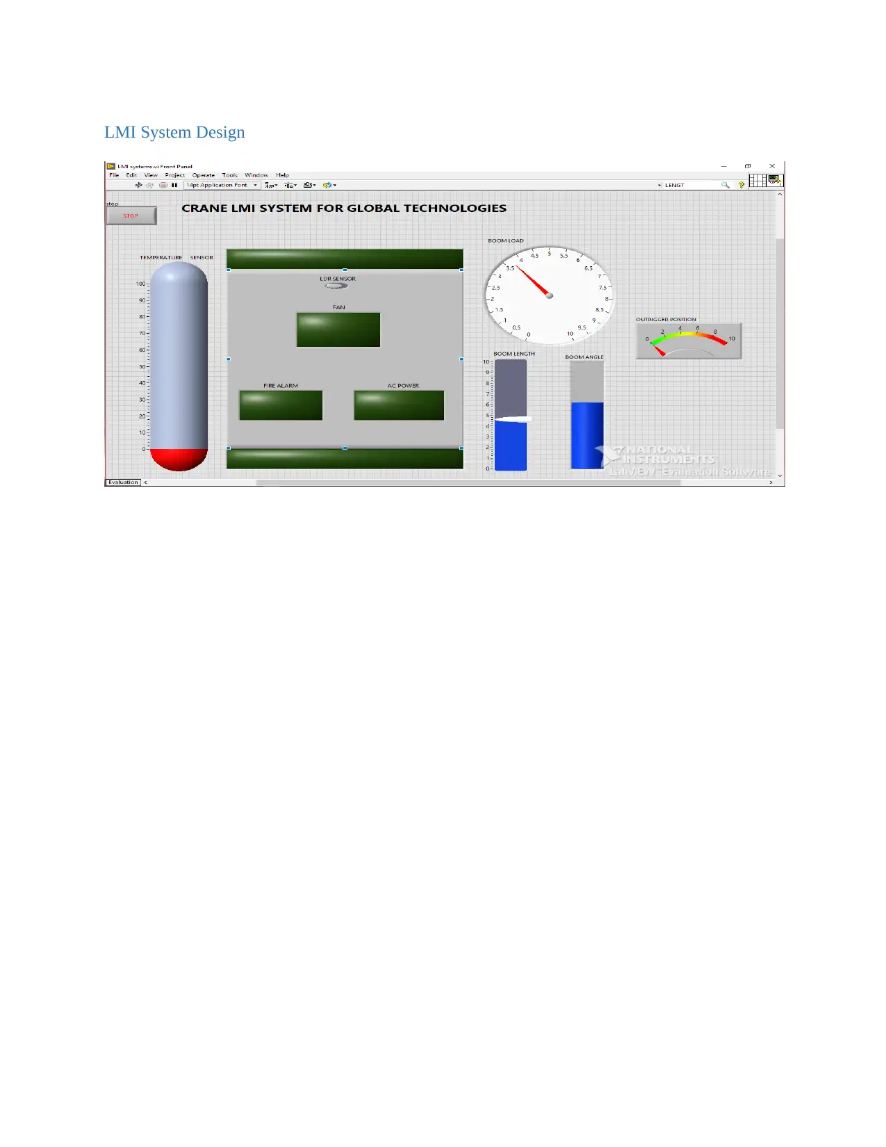
LMI System Design
Document Page
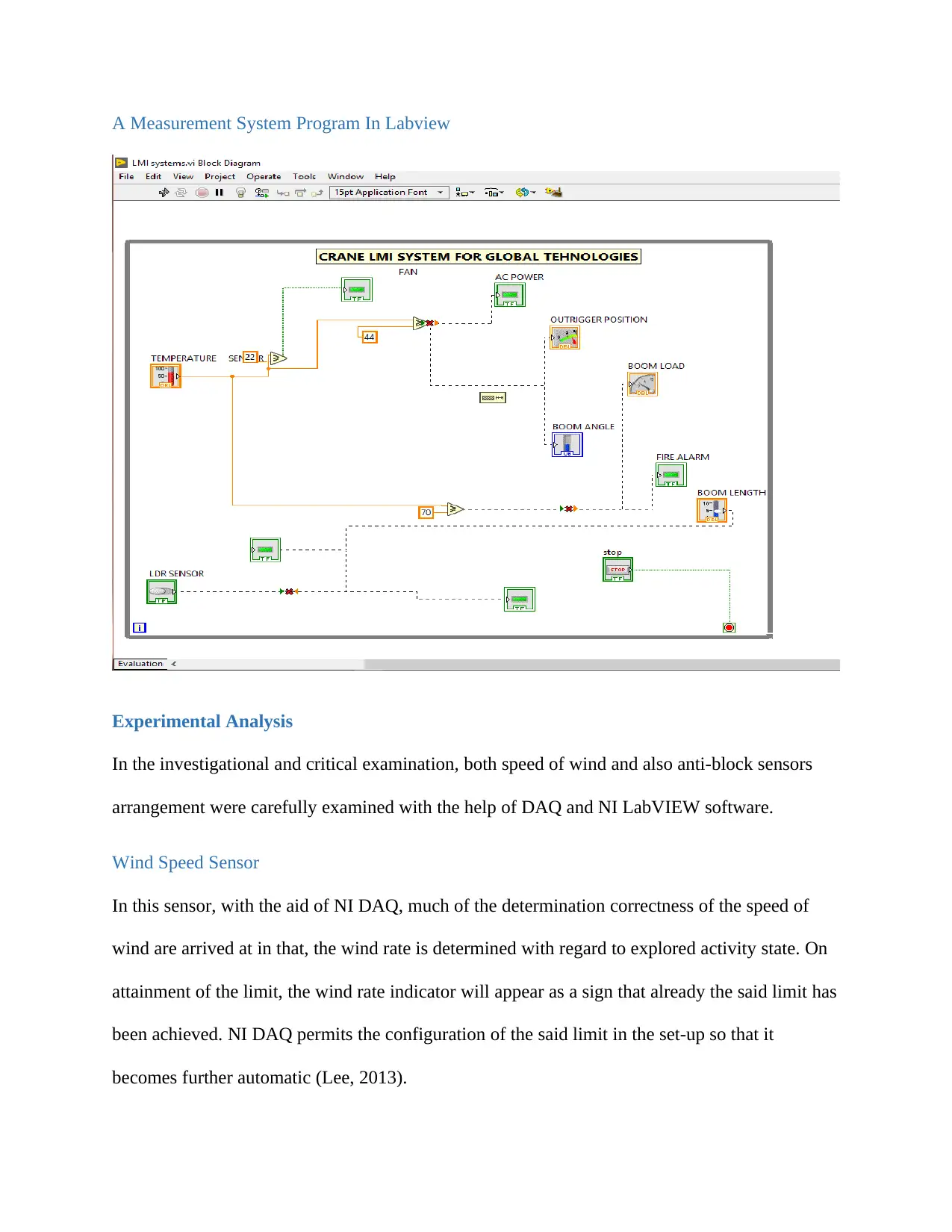
A Measurement System Program In Labview
Experimental Analysis
In the investigational and critical examination, both speed of wind and also anti-block sensors
arrangement were carefully examined with the help of DAQ and NI LabVIEW software.
Wind Speed Sensor
In this sensor, with the aid of NI DAQ, much of the determination correctness of the speed of
wind are arrived at in that, the wind rate is determined with regard to explored activity state. On
attainment of the limit, the wind rate indicator will appear as a sign that already the said limit has
been achieved. NI DAQ permits the configuration of the said limit in the set-up so that it
becomes further automatic (Lee, 2013).

Secure Best Marks with AI Grader

Need help grading? Try our AI Grader for instant feedback on your assignments.
Document Page
With use of NI LabVIEW in examination of this sensor, you realize that after this set up model,
the software configuration can’t allow laid limit get configured. Therefore, it is now hard to have
in the system, the limit meant for determination of the rate of wind. Moreover, the wind rate is
supposed to be laid or be set to its limit. As a result, this will enable the crane to generate an
automated wind speed detection system that will give a summary of the whole performance. This
is because it is disallowed to operate a crane within high speeds of wind for the safety and
wellbeing reasons. Additionally, the bundle or load that is being moved by the crane can be
swayed off by the strong winds (Anon, n.d.).
Anti Block Sensor System
This system is designed to have the crane’s hook monitored against banging itself against the
boom’s head. The sensor’s evaluation is done by use of NI DAQ and NI LabVIEW software. In
employing NI DAQ, the gap separating both the hook and the boom’s head as observed and laid
is found to be roughly 12 inches (Kaitl, 2020). On the other hand, the NI LabVIEW’s laid limit is
just 3 inches. Literally, this 3 inches’ distance is quite dangerous. This is because whenever there
is an error, the boom head will likely crush the crane’s hook. Additionally, the load being
handled by the crane hook may be swayed off by the strong winds while stacking. This may in
return meddle with the space distance, causing the outcome (Anon, n.d.).
An Evaluation Of Signal Conditioning Elements That Are Required To Measure The Load
Using Strain Gauges.
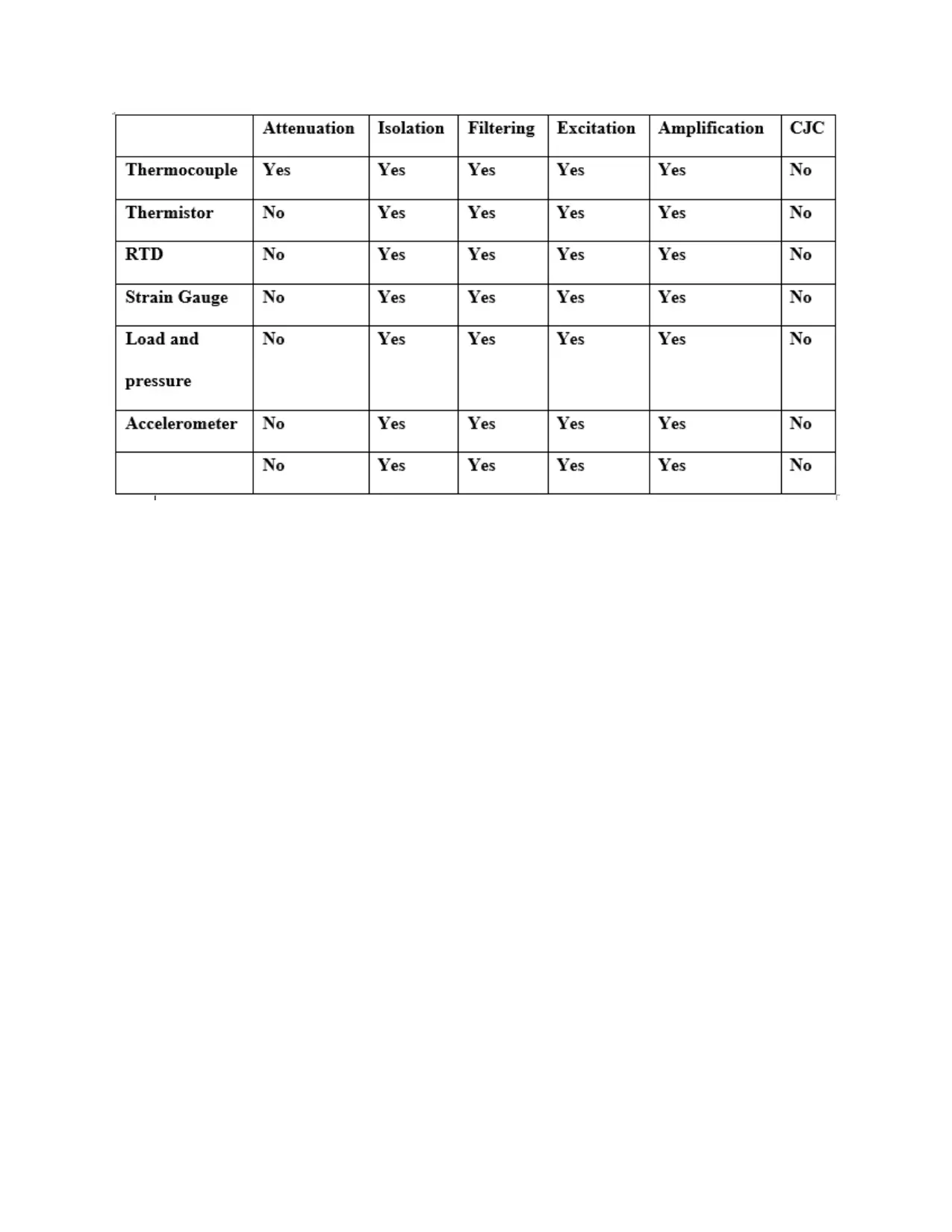
Aiming at best measurements, it’s crucial to understand the gesture or signal conditioning of any
kind of measurement or examination. The best gesture conditionings according to the
measurement or examination required are demonstrated and portrayed by the table below.
Document Page
Document Page
Proposal for the next phases of development of;
A. Adopting controllers, lower in price rather than present ones
Taking a look at the sensor set up in relation to its design and expansion overall cost,
finding a controller with low cost might just be quite productive since the present controller
is quite costly. This makes it very hard to design an advanced system coming with great
automation (Salánki & Sarvajcz, 2019).
B. More data transmission means; wired as well as wireless means
Transmission of data under mechanical means has proved to be slow and wastes time for
the on-going expansion of the sensor set-up. It becomes quite difficult for the sensor to
design an even rely of data (Cao & Zheng, 2013). This makes the entire exercise extremely
slow. With the coming up of wired as well as wireless modes of data transmission, it is
likely to be more productive since it will bring an immediate way of relying data. The
transmission of data will be on-time if there is usage of the present-day means of
transmission of data.
C. Suggestions for the next development stages should include usage of the Internet of Things,
commonly referred to as IoT. This is the best mode of communication as well as expanding
technology within the sector of engineering. Its use therefore in cranes’ manufacturing as
well as expansion could result in remote controlled crane set-ups, with limited or no need
for crane operators physically operating and handling cranes (Tumari et al., 2012).

Paraphrase This Document

Need a fresh take? Get an instant paraphrase of this document with our AI Paraphraser
Document Page
Conclusion
Using the next generation skills and methods in creating and expanding crane LMI set-up is
therefore encouraged as compared to present technologies that is being used. Going forward
therefore, universal technology should start utilizing the most present-day technologies in
creation of crane sensor systems.
Document Page
References
Anon, (n.d.). Crane System Types - LMI - RCI - Scale and Control Inc.. [online] Available at:
https://www.scaleandcontrol.com/crane-lmi-rci.html [Accessed 2019].
Anon, (n.d.). Cranesmart Systems - Crane Safety. Made Simple.. [online] Available at:
http://cranesmart.com/ [Accessed 2019].
Anon, (n.d.). How to run a crane computer lmi - YouTube. [online] Available at:
https://www.youtube.com/watch?v=uygeCH6_dw8 [Accessed 2019].
Anon, (n.d.). The Cranesmart LMI System - Cranesmart Systems - Crane .... [online] Available
at: http://cranesmart.com/wp-content/uploads/2017/01/900-Cranesmart-LMI-Rev-11-FEB-4.-
2015.pdf [Accessed 2019].
Cao, L. and Zheng, M., (2013). Lifting Capacity Detection System of Tower Crane Based on
LabVIEW. Applied Mechanics and Materials, 380-384, pp.860-865.
Kaitl, K., (2020). The Development of Image Capturing System Applied in Shooting Simulator
using LabVIEW. WSEAS TRANSACTIONS ON SIGNAL PROCESSING, 16.
Komnaska, M. (2013). Crane control system design via lmi-approach. Electronics and Control
Systems, 3(37).
Lee, M. (2013). Design of a Robust Track-Following System Using Genetic Algorithm and LMI
Approach. Korea Institute of Information Technology Review, 11(8).
Patel, H. and Patel, J., (2015). LabVIEW based ‘nonlintool’ for analysis and design of nonlinear
control system. Computer Applications in Engineering Education, 24(2), pp.195-201.
Salánki, D. and Sarvajcz, K., (2019). Development of a Gait Recognition System in NI
LabVIEW Programming Language. Műszaki Tudományos Közlemények, 11(1), pp.167-170.
1 out of 12
[object Object]

Your All-in-One AI-Powered Toolkit for Academic Success.

Available 24*7 on WhatsApp / Email

[object Object]