Crane LMI System for Global Technologies
VerifiedAdded on 2022/10/10
|8
|1960
|272
AI Summary
This article discusses the Load Moment Indicator (LMI) system in cranes, including its various components such as length sensor, anti two-block sensor, load plate system, wind speed sensor, and angle and length transmitter system. It also provides an experimental analysis of wind speed and anti-block sensor systems, and a proposal for the next phases of development of the crane LMI system. The article concludes by recommending the use of modern technologies in the design and development of the crane LMI system.
Contribute Materials
Your contribution can guide someone’s learning journey. Share your
documents today.

CRANE LMI SYSTEM FOR GLOBAL TECHNOLOGIES
Student Name
Professor’s Name
Date
Student Name
Professor’s Name
Date
Secure Best Marks with AI Grader
Need help grading? Try our AI Grader for instant feedback on your assignments.
INTRODUCTION
The Load Moment Indicator LMI is utilized in pressure driven cranes. LMI in cranes is utilized in
perusing the estimation of the heaps utilizing sets of transducers which uses the weight, that
thusly peruses the weight of the chamber that Is found in the chamber of the lift. One of the
upsides of the Load Moment Indicator in cranes, the blast weight is incorporated as a major
aspect of the computation of the heap in the general count. The ability of the framework
subsequently can make computations in the components impact which incorporates the ice and
wind on the limit of the lifting which is accessible (Anon, n.d.).
LMI FRAMEWORKS IN CRANES
The LMI framework in cranes incorporates the accompanying;
Length sensor framework
This is one of the most basic frameworks in the crane LMI frameworks. The framework is
worked at estimating the edge position of the controlling wheel just as the rate at which the
directing wheel can turn. The sensor has an output instrument which is utilized for giving the
information controlling wheel position and turning in degrees. The framework is situated in the
sensor bunch which is situated in the segment of the guiding. For the affirmation of information
and decrease of excess, the crane is comprised of at any rate two point sensor frameworks. The
ESC module in the framework needs to get at any rate two sign with the end goal of affirmation
and confirmation of the situation of the guiding (Anon, n.d.).
Anti two Block sensor framework
The counter square sensor framework in the cranes are utilized for checking of the upper snare of
the crane for the reasons of wellbeing which accompanies the equivalent. The sensor forbids the
snare of the crane from slamming off against the leader of the blast for the most part when the
heap is being elevated. The crisis switches for the draw wire switches with the extremely
extraordinary plan of pulling for this situation with incorporation of the stabilizer satisfaction.
The stabilizer is connected for this situation for keeping the shut the contact switch (Anon, n.d.).
Utilizing the counter square sensor, when the snare square discover its way to the highest point,
the snare hits the stabilizer that ascents consequently which opens the contact.

Because of the significant capacity which is performed by the sensor, the switch along these lines
must be especially dependable since the switch is presented to nearly the whole piece of the kinds
of climate subsequently it must be particularly safe when it comes into contact with salt water.
Load plate framework
This framework is utilized in cranes which are utilized for stacking exceptionally overwhelming
products, for example, the steel factories and the steel plates, loops and the maritime vessels. the
framework is utilized for checking the stacking of the plate vessels. The plate burden is a stacking
space where the heap is held at the level top plate and it is then moved to another vessel (Anon,
n.d.). The framework is comprised of the accompanying components; It has the capacity of
making a solid power for pleasing expanded plate which is utilized for stacking wide ships. The
framework has the capacity of controlling the wide leg opening which is used in the emptying
without the slewing procedure occurring in every single cycle (Komnaska, 2013).
Wind speed sensor
Normally, the cranes are structured and created so that they can't work in the situations of high
wind speed for the wellbeing of the cranes and the administrator. This is the reason the cranes are
fitted with wind sensor framework which is utilized for deciding the wellbeing of the activity of
the crane. The framework estimates the force of the breezes and previously and during the
activity procedure. In the vast majority of the cranes, wind caution framework is additionally
fitted in states of raising breezes (Lee, 2013).
Angle and length transmitter framework
This crane framework is utilized for estimating the expansion of the extending chamber and the
point of it in connection of the power of gravity. The edge and the length transmitter framework
is the utilized for a wide range of cranes. It is worked at estimating the blast length and the blast
edge on the cranes and the man lifts adaptive. Utilizing this sort of framework, cruel conditions in
the portable cranes is hence expelled (Lee, 2013).
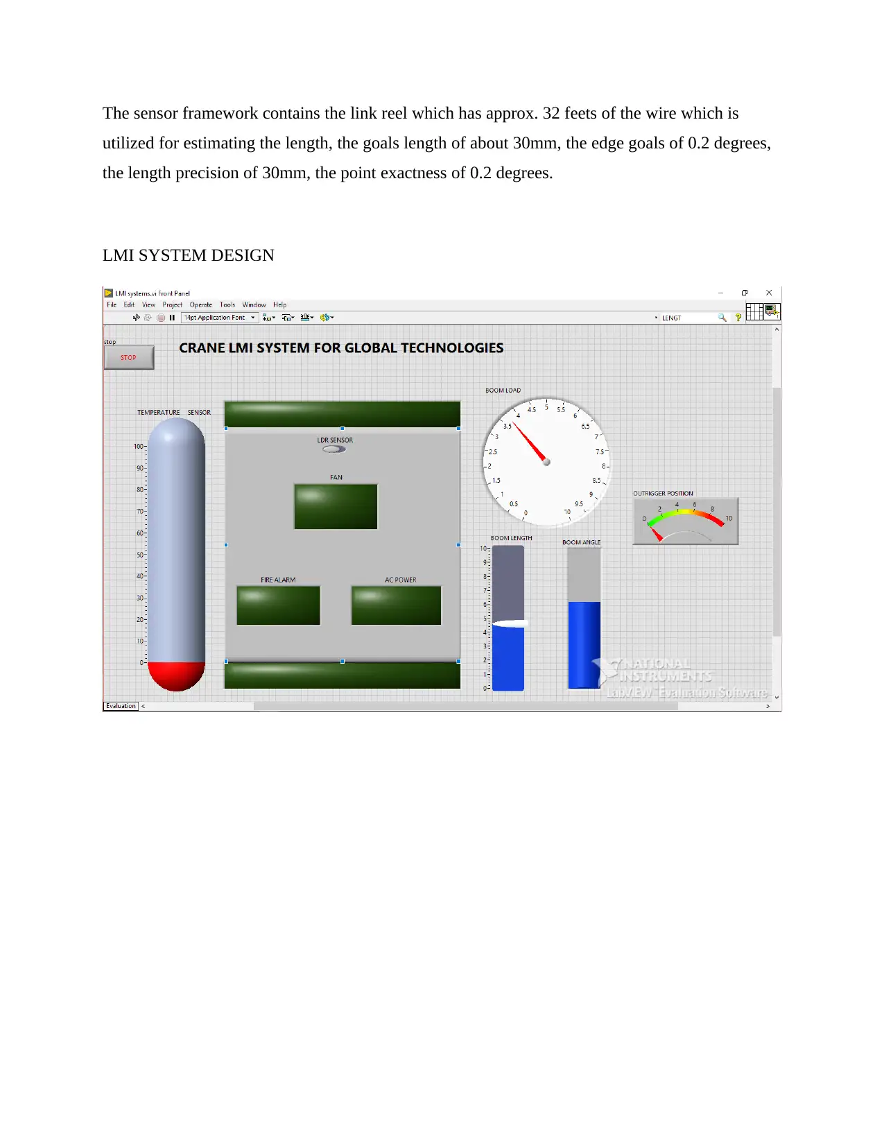
The sensor framework contains the link reel which has approx. 32 feets of the wire which is
utilized for estimating the length, the goals length of about 30mm, the edge goals of 0.2 degrees,
the length precision of 30mm, the point exactness of 0.2 degrees.
LMI SYSTEM DESIGN
utilized for estimating the length, the goals length of about 30mm, the edge goals of 0.2 degrees,
the length precision of 30mm, the point exactness of 0.2 degrees.
LMI SYSTEM DESIGN
Secure Best Marks with AI Grader
Need help grading? Try our AI Grader for instant feedback on your assignments.
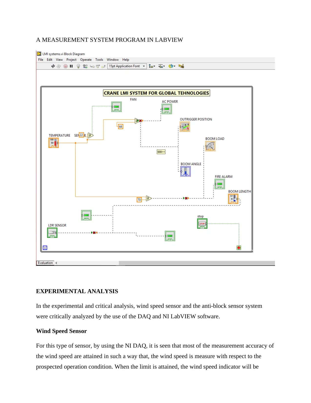
A MEASUREMENT SYSTEM PROGRAM IN LABVIEW
EXPERIMENTAL ANALYSIS
In the experimental and critical analysis, wind speed sensor and the anti-block sensor system
were critically analyzed by the use of the DAQ and NI LabVIEW software.
Wind Speed Sensor
For this type of sensor, by using the NI DAQ, it is seen that most of the measurement accuracy of
the wind speed are attained in such a way that, the wind speed is measure with respect to the
prospected operation condition. When the limit is attained, the wind speed indicator will be

shown as an indicator that the set limit of wind has been attained. The NI DAQ allows the set
limit to be configured in the system to make it more automated (Lee, 2013).
By using the NI LabVIEW in the analysis of the sensor, it is seen that the software configuration
after the design of the system does not permit the set limit to be configured hence it becomes
difficult to set the limit for the measurement of wind speed in the system. Literary, the wind
speed is supposed to be set to its limit which in turn helps the crane to create an automated wind
speed detection system which in turn gives an overview of the operation since operating the crane
in the high winds is not permitted for security reasons as the load carried by the crane can be
swayed off by the winds (Anon, n.d.).
Anti Block Sensor System
As discussed earlier, the anti block sensor system is functioned in monitoring the hook of the
crane against crushing off against the head of the boom. This sensor is analyzed using the NI
DAQ and the NI LabVIEW software. Using the NI DAQ, it is seen that the distance at which the
hook and the head of the boom is monitored as set as maximum is about 12 inches as compared
to the NI LabVIEW which sets its limit at 3 inches. The distance of 3 inches is very much
technical and dangerous as in case of any slight mistake or error, then the boom head is likely to
be crushed off by the hook of the crane. This is because sometimes the load which is being
carried by the crane can be swayed off by the winds while loading hence it might interfere with
the gap distance hence causing the effect (Anon, n.d.).
AN EVALUATION OF SIGNAL CONDITIONING ELEMENTS THAT ARE REQUIRED
TO MEASURE THE LOAD USING STRAIN GAUGES.
In order to achieve the very best measurements, then it is important to understand the signal
conditioning of every measurement type. The table below indicates and shows the best
conditioning of signals as per the measurement which is needed.

Attenuation Isolation Filterin
g
Excitation Amplification CJ
C
Thermocoupl
e
Yes Yes Yes Yes Yes No
Thermistor No Yes Yes Yes Yes No
RTD No Yes Yes Yes Yes No
Strain Gauge No Yes Yes Yes Yes No
Load and
pressure
No Yes Yes Yes Yes No
Accelerometer No Yes Yes Yes Yes No
No Yes Yes Yes Yes No
PROPOSAL FOR THE NEXT PHASES OF DEVELOPMENT OF;
A. Using of a low-cost controller instead of the current one
Introduction of a low cost controller will be more effective as far as the total cost of
design and development of the crane sensor systems are concerned. The current controller
is very much expensive hence making it very difficult to create and expounded system
which much sophistication and automation (Tumari et al., 2012).
B. Other methods of data transmissions; wireless or wired data transmission
Mechanical way of transmitting data has been very slow and time wasting for the current
development of the sensor system. The sensor finds it very hard to create a smooth rely of
data hence making the whole process very slow. With the introduction of the wireless or
even wired means of transmitting data, this will be more effective as its will create an
instant package of data rely. Data transmission will be real time by using of the modern
means of data transmission (Tumari et al., 2012).
C. Proposal for the next phases of development to include the use of the Internet of Things
Paraphrase This Document
Need a fresh take? Get an instant paraphrase of this document with our AI Paraphraser

Internet of Things popularly known as the IoT is the most effective means of
communication and improving technology in the engineering industry. Employing the use
of it in the design and development of the crane LMI systems, this will create a remote
controlled crane systems where there is no need for a crane operator to be physically on
top of the crane for operation and controlling (Tumari et al., 2012).
CONCLUSION
In conclusion therefore, employing the next generation techniques in the design and development
of the crane LMI system is the most recommended as compared to the current technologies which
are used. Global technology should therefore begin employing the most modern technologies in
the design of the sensor systems in cranes.
References
Anon, (n.d.). Crane System Types - LMI - RCI - Scale and Control Inc.. [online] Available at:
https://www.scaleandcontrol.com/crane-lmi-rci.html [Accessed 2019].
Anon, (n.d.). Cranesmart Systems - Crane Safety. Made Simple.. [online] Available at:
http://cranesmart.com/ [Accessed 2019].
Anon, (n.d.). How to run a crane computer lmi - YouTube. [online] Available at:
https://www.youtube.com/watch?v=uygeCH6_dw8 [Accessed 2019].
Anon, (n.d.). The Cranesmart LMI System - Cranesmart Systems - Crane .... [online] Available
at: http://cranesmart.com/wp-content/uploads/2017/01/900-Cranesmart-LMI-Rev-11-FEB-4.-
2015.pdf [Accessed 2019].
Komnaska, M. (2013). Crane control system design via lmi-approach. Electronics and Control
Systems, 3(37).
Lee, M. (2013). Design of a Robust Track-Following System Using Genetic Algorithm and LMI
Approach. Korea Institute of Information Technology Review, 11(8).
Tumari, M., Saealal, M., Wahab, Y. and Ghazali, M. (2012). H-Infinity Controller with LMI
Region Schemes for a Lab-Scale Rotary Pendulum Crane System. International Journal of
Signal System Control and Engineering Application, 5(1), pp.14-20.
1 out of 8
Your All-in-One AI-Powered Toolkit for Academic Success.
+13062052269
info@desklib.com
Available 24*7 on WhatsApp / Email
![[object Object]](/_next/static/media/star-bottom.7253800d.svg)
Unlock your academic potential
© 2024 | Zucol Services PVT LTD | All rights reserved.


