MP4702 Advanced Materials: Creep, TTT, and Material Selection Task
VerifiedAdded on 2023/05/28
|13
|2048
|471
Homework Assignment
AI Summary
This assignment solution covers several key concepts in materials science and engineering. It begins by discussing creep mechanisms, specifically bulk diffusion, and its dependence on stress and grain size. The solution then explores how single crystal parts and alloying elements affect creep. The second question focuses on TTT diagrams for plain carbon steel, explaining quenching and tempering processes, martensitic transformation, and hardenability. Strategies to increase transformation without changing geometry are also discussed. Finally, the solution addresses a material selection problem involving a truck suspension system, outlining objectives, constraints, and free variables for mass reduction. It includes mathematical representations for stiffness, deflection, and material indices, culminating in material selection based on performance and fracture toughness. The document concludes with a discussion of thermosetting polymers, their creep behavior, and a comparison with thermoplastics, and a connecting rod design problem focusing on constraints, objectives, and material selection criteria.
SOLUTION 1:
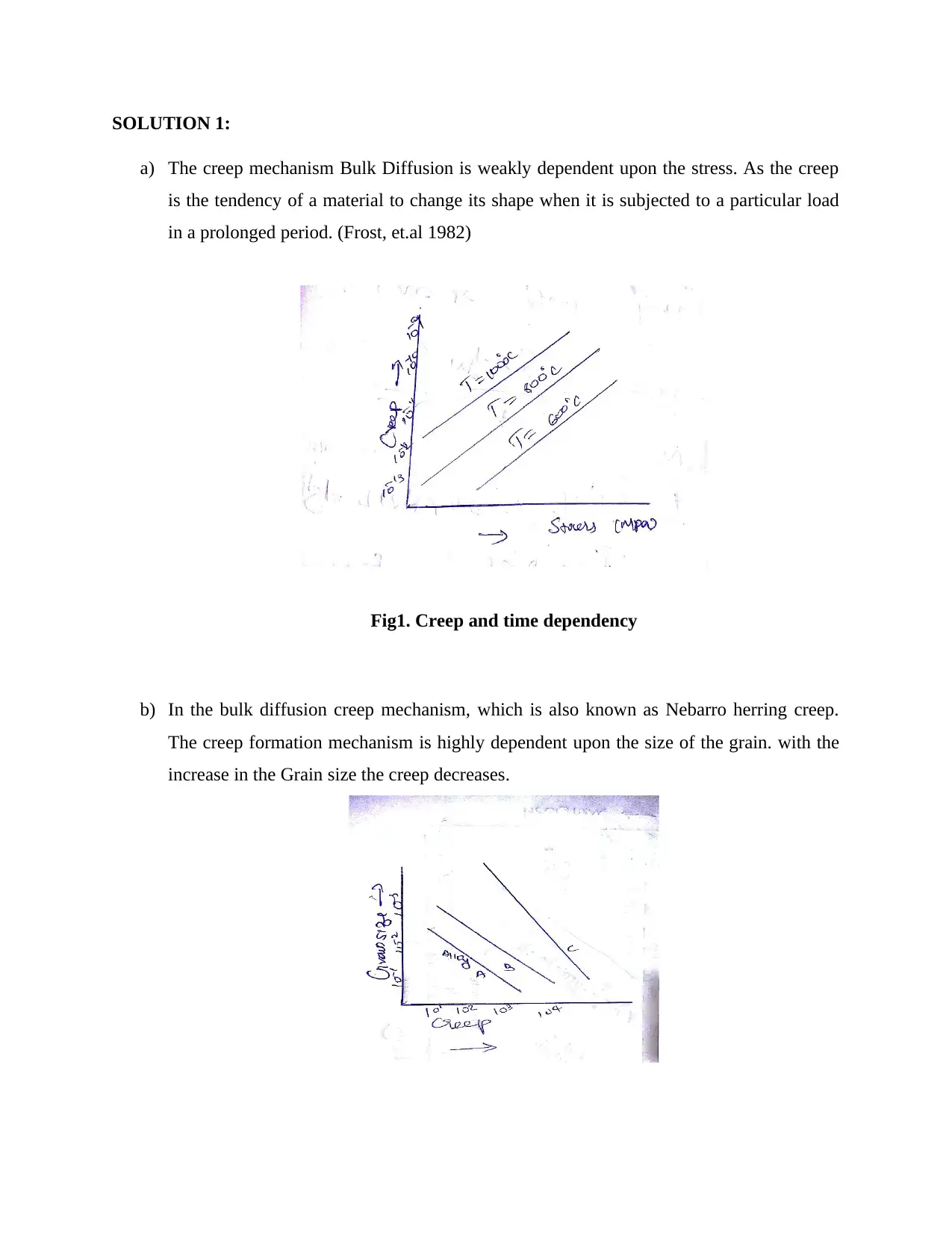
a) The creep mechanism Bulk Diffusion is weakly dependent upon the stress. As the creep
is the tendency of a material to change its shape when it is subjected to a particular load
in a prolonged period. (Frost, et.al 1982)
Fig1. Creep and time dependency
b) In the bulk diffusion creep mechanism, which is also known as Nebarro herring creep.
The creep formation mechanism is highly dependent upon the size of the grain. with the
increase in the Grain size the creep decreases.
Paraphrase This Document
Need a fresh take? Get an instant paraphrase of this document with our AI Paraphraser
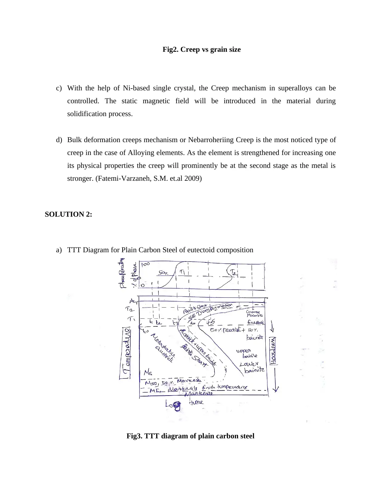
Fig2. Creep vs grain size
c) With the help of Ni-based single crystal, the Creep mechanism in superalloys can be
controlled. The static magnetic field will be introduced in the material during
solidification process.
d) Bulk deformation creeps mechanism or Nebarroheriing Creep is the most noticed type of
creep in the case of Alloying elements. As the element is strengthened for increasing one
its physical properties the creep will prominently be at the second stage as the metal is
stronger. (Fatemi-Varzaneh, S.M. et.al 2009)
SOLUTION 2:
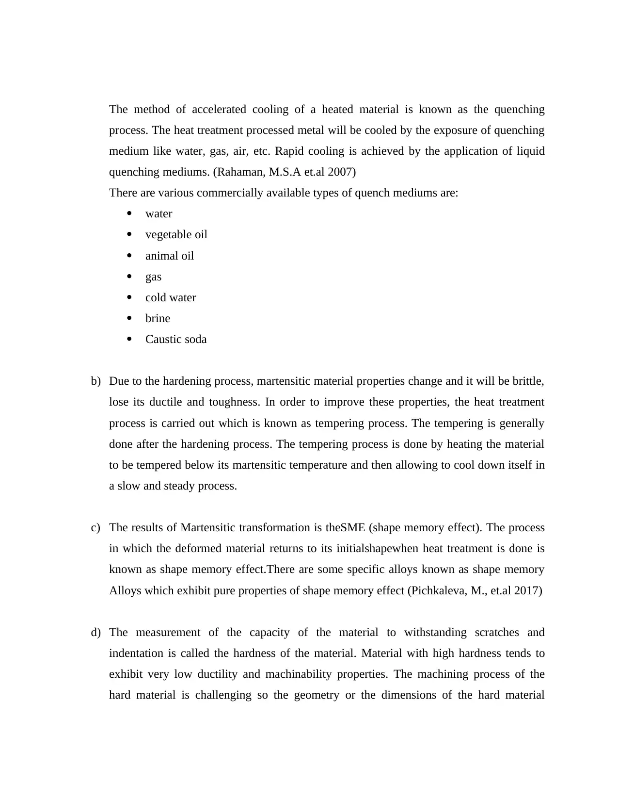
a) TTT Diagram for Plain Carbon Steel of eutectoid composition
Fig3. TTT diagram of plain carbon steel
The method of accelerated cooling of a heated material is known as the quenching
process. The heat treatment processed metal will be cooled by the exposure of quenching
medium like water, gas, air, etc. Rapid cooling is achieved by the application of liquid
quenching mediums. (Rahaman, M.S.A et.al 2007)
There are various commercially available types of quench mediums are:
water
vegetable oil
animal oil
gas
cold water
brine
Caustic soda
b) Due to the hardening process, martensitic material properties change and it will be brittle,
lose its ductile and toughness. In order to improve these properties, the heat treatment
process is carried out which is known as tempering process. The tempering is generally
done after the hardening process. The tempering process is done by heating the material
to be tempered below its martensitic temperature and then allowing to cool down itself in
a slow and steady process.
c) The results of Martensitic transformation is theSME (shape memory effect). The process
in which the deformed material returns to its initialshapewhen heat treatment is done is
known as shape memory effect.There are some specific alloys known as shape memory
Alloys which exhibit pure properties of shape memory effect (Pichkaleva, M., et.al 2017)
d) The measurement of the capacity of the material to withstanding scratches and
indentation is called the hardness of the material. Material with high hardness tends to
exhibit very low ductility and machinability properties. The machining process of the
hard material is challenging so the geometry or the dimensions of the hard material
⊘ This is a preview!⊘
Do you want full access?
Subscribe today to unlock all pages.

Trusted by 1+ million students worldwide
should be simple and easy to machine no complex curves shall be implemented in the
design (Taufik, A., et.al 2018)
e) The alloying of the carbon in steel found to increase its hardness to a greater extent. The
carbon decreases the ferrite and pearlite formation and increases the hardness of the
material. The hardness of a material is directly proportional to the percentage of carbon
content in it. There are many processes to improve the hardness such as Carburizing,
nitriding, carbonitriding, flame hardening, induction hardening, etc.
The solution for Question3:
Function a) Suspension of Truck
Constraints a) Fixed length
b) Max displacement is given
c) Stiffness is given
Objective a) Mass reduction or minimization
Free variables a) The width of the leaf spring
b) The thickness of the leaf spring
c) The required material selection
Objective: Mass reduction
Total mass,
m=b Ltρ
Here,
Paraphrase This Document
Need a fresh take? Get an instant paraphrase of this document with our AI Paraphraser

L – Spring Length
b -Spring breadth
t – Spring overall thickness
ρis the density of the material.
Length is fixed.
The breadth and the thickness are variable and can be changed.
Constraints:
The Stiffness S is given as:
S = F/ δ
Here,
F is the force
δ is the deflection.
The Maximum displacement δmaxis given by the equation:
δmax =1
6
σf L2
tE
Where,
L is the length
E is the Young's modulus
T is the thickness

σ f is the stress applied.
The above equation may be rewritten for thickness as:
t= δmax (6)
σ f E L2
Now,
We have the deflection equation:
δ= 1
48
F L3
EI
Here,
I am the moment of inertia
F is the force
L is the length
E is the Young’s modulus
Substitute the Value of δ and the Value of L2 in the Stiffness equation we get:
S= F
δ
S= 48 EI
FL3 = 4 Eb t3
L3
Now,
Calculate b from the above equation:
⊘ This is a preview!⊘
Do you want full access?
Subscribe today to unlock all pages.

Trusted by 1+ million students worldwide
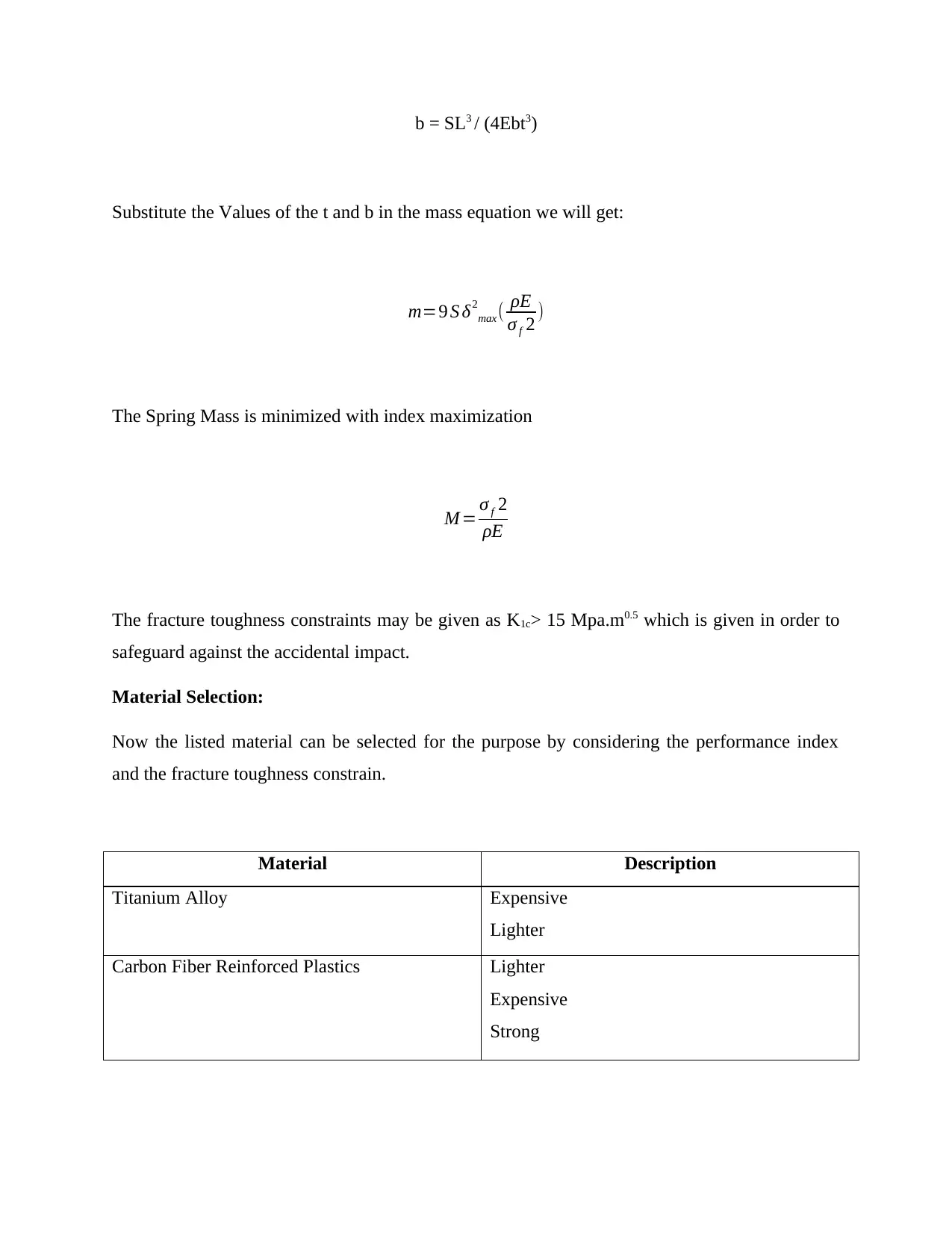
b = SL3 / (4Ebt3)
Substitute the Values of the t and b in the mass equation we will get:
m=9 S δ2
max( ρE
σ f 2 )
The Spring Mass is minimized with index maximization
M = σ f 2
ρE
The fracture toughness constraints may be given as K1c> 15 Mpa.m0.5 which is given in order to
safeguard against the accidental impact.
Material Selection:
Now the listed material can be selected for the purpose by considering the performance index
and the fracture toughness constrain.
Material Description
Titanium Alloy Expensive
Lighter
Carbon Fiber Reinforced Plastics Lighter
Expensive
Strong
Paraphrase This Document
Need a fresh take? Get an instant paraphrase of this document with our AI Paraphraser
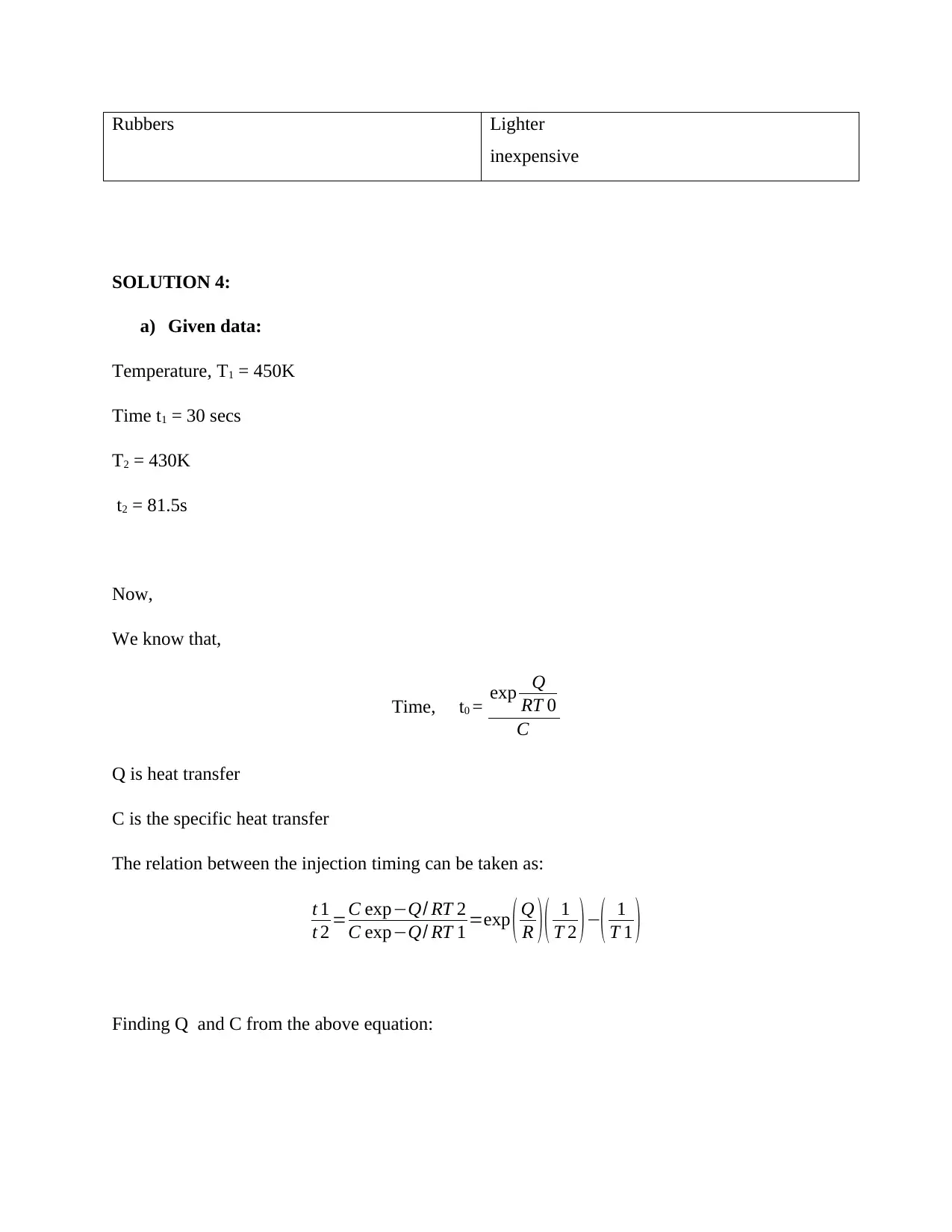
Rubbers Lighter
inexpensive
SOLUTION 4:
a) Given data:
Temperature, T1 = 450K
Time t1 = 30 secs
T2 = 430K
t2 = 81.5s
Now,
We know that,
Time, t0 = exp Q
RT 0
C
Q is heat transfer
C is the specific heat transfer
The relation between the injection timing can be taken as:
t 1
t 2 =C exp−Q/ RT 2
C exp−Q/ RT 1 =exp ( Q
R )( 1
T 2 )−( 1
T 1 )
Finding Q and C from the above equation:
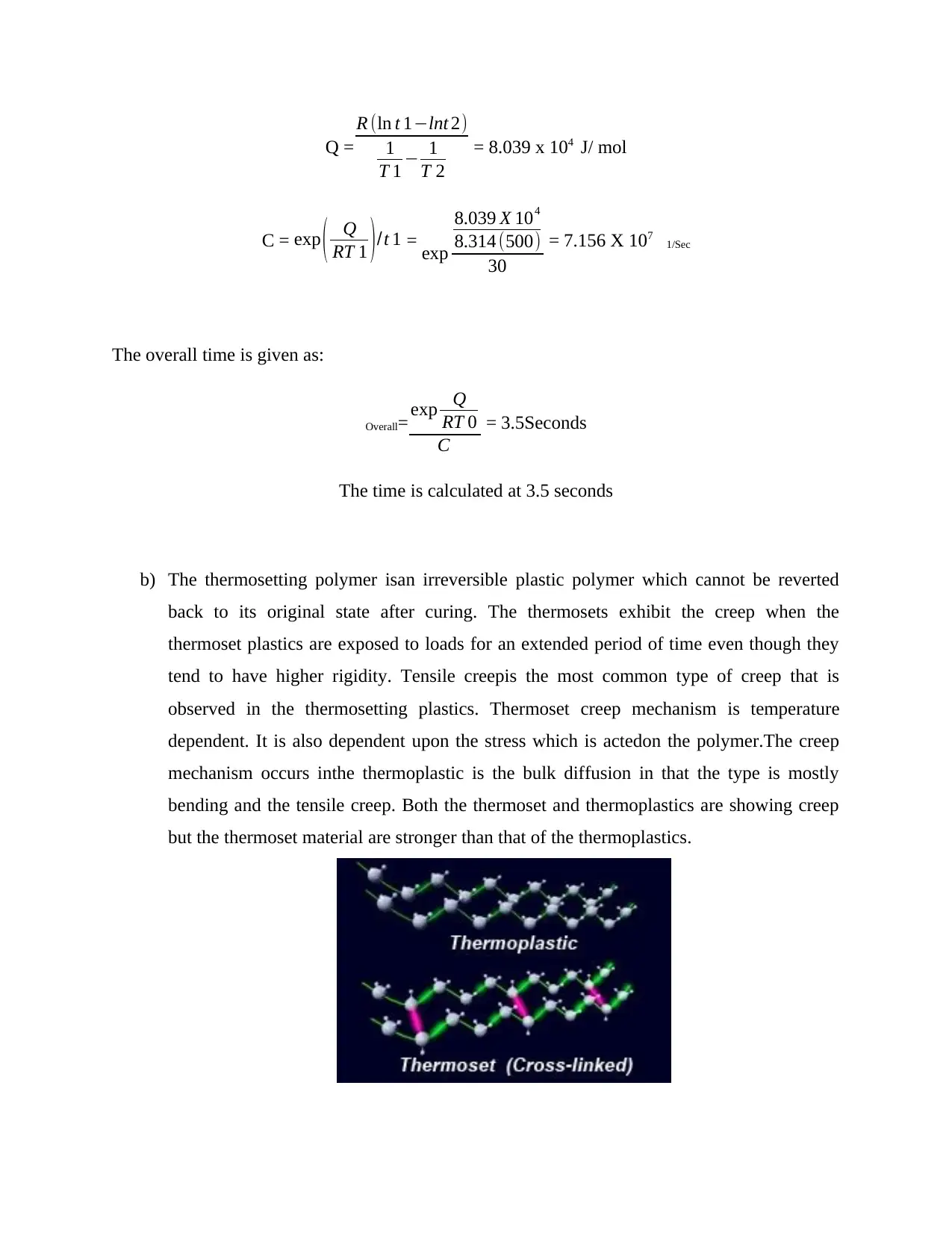
Q =
R (ln t 1−lnt 2)
1
T 1 − 1
T 2
= 8.039 x 10⁴ J/ mol
C = exp ( Q
RT 1 )/t 1 = exp
8.039 X 10⁴
8.314 (500)
30
= 7.156 X 10⁷ 1/Sec
The overall time is given as:
Overall= exp Q
RT 0
C
= 3.5Seconds
The time is calculated at 3.5 seconds
b) The thermosetting polymer isan irreversible plastic polymer which cannot be reverted
back to its original state after curing. The thermosets exhibit the creep when the
thermoset plastics are exposed to loads for an extended period of time even though they
tend to have higher rigidity. Tensile creepis the most common type of creep that is
observed in the thermosetting plastics. Thermoset creep mechanism is temperature
dependent. It is also dependent upon the stress which is actedon the polymer.The creep
mechanism occurs inthe thermoplastic is the bulk diffusion in that the type is mostly
bending and the tensile creep. Both the thermoset and thermoplastics are showing creep
but the thermoset material are stronger than that of the thermoplastics.
⊘ This is a preview!⊘
Do you want full access?
Subscribe today to unlock all pages.

Trusted by 1+ million students worldwide
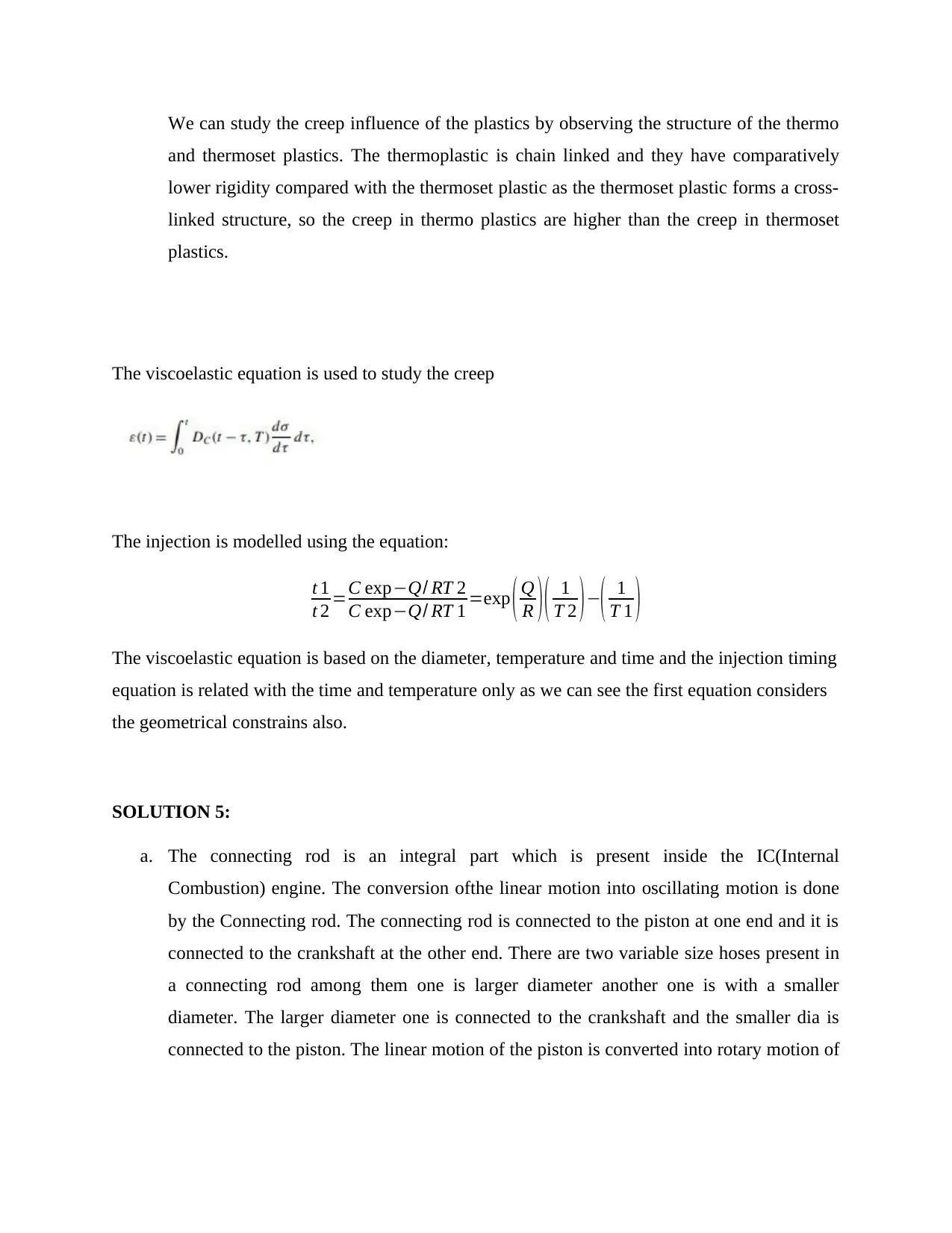
We can study the creep influence of the plastics by observing the structure of the thermo
and thermoset plastics. The thermoplastic is chain linked and they have comparatively
lower rigidity compared with the thermoset plastic as the thermoset plastic forms a cross-
linked structure, so the creep in thermo plastics are higher than the creep in thermoset
plastics.
The viscoelastic equation is used to study the creep
The injection is modelled using the equation:
t 1
t 2 =C exp−Q/ RT 2
C exp−Q/ RT 1 =exp ( Q
R )( 1
T 2 )−( 1
T 1 )
The viscoelastic equation is based on the diameter, temperature and time and the injection timing
equation is related with the time and temperature only as we can see the first equation considers
the geometrical constrains also.
SOLUTION 5:
a. The connecting rod is an integral part which is present inside the IC(Internal
Combustion) engine. The conversion ofthe linear motion into oscillating motion is done
by the Connecting rod. The connecting rod is connected to the piston at one end and it is
connected to the crankshaft at the other end. There are two variable size hoses present in
a connecting rod among them one is larger diameter another one is with a smaller
diameter. The larger diameter one is connected to the crankshaft and the smaller dia is
connected to the piston. The linear motion of the piston is converted into rotary motion of
Paraphrase This Document
Need a fresh take? Get an instant paraphrase of this document with our AI Paraphraser

the crankshaft with the help of oscillating motion achieved in the connecting rod (Kou,
S., et.al 2017)
b. The given constraints in the problem are the length is fixed, must be lighter in weight,
Fatigue and buckling should be lowered.
c. The objectives are :
Withstand Force up to 20KN.
Lighter in weight.
Strong.
d. The variable over which we have the control is known as free variables they are not
fixed. In this sytem the free variables are:
Material choice
Breadth
Width
e. The mass of the connecting rod is given as:
Mass, m = (M1)+ (M2)
M1 Rectangle
M2 Circle
m=¿ ) ρ in kgs
Here,
ρ- the density of the material
D diameter
b- breadth
W- width

t- thickness
f. The mathematical representation the variables which are responsible for the fatigue in the
form in indices are known as performance index for the fatigut
g. The mass of connecting rod is calculated previously as:
m=¿ ) ρ in kgs
b = 𝜶W
m=αW2 t + 2( π
4 D2) X ρ
h. The buckling material index
The material index can be found as:
M = E/ρ
We have,
FBuckling = π2 EI
L2
E = FL2 / π2 I
Substituting on first eqn:
M = FL2ρ / π2 I
i. Application of two performance indices gives greater control over the product design and
the quality. It also improves the performance of the product for a long time.
⊘ This is a preview!⊘
Do you want full access?
Subscribe today to unlock all pages.

Trusted by 1+ million students worldwide
1 out of 13
Related Documents
Your All-in-One AI-Powered Toolkit for Academic Success.
+13062052269
info@desklib.com
Available 24*7 on WhatsApp / Email
![[object Object]](/_next/static/media/star-bottom.7253800d.svg)
Unlock your academic potential
Copyright © 2020–2026 A2Z Services. All Rights Reserved. Developed and managed by ZUCOL.


