Database Analysis and Design: A Case Study of Dominican College
VerifiedAdded on 2024/06/12
|102
|8346
|148
AI Summary
This report presents a comprehensive analysis and design of a relational database system for Dominican College, a higher education institution located in New York City. The database, developed using MS Access, aims to manage student, course, lecturer, and administrative data efficiently. The report covers various aspects of database design, including data modeling, normalization, query language implementation, and user interface enhancement. It also includes a critical review and testing of the system, along with documentation for implementation and user guidance.
Contribute Materials
Your contribution can guide someone’s learning journey. Share your
documents today.
Database Analysis and Design
1
1
Secure Best Marks with AI Grader
Need help grading? Try our AI Grader for instant feedback on your assignments.
Contents
Introduction................................................................................................................................7
LO1 Understand data models and database technologies..........................................................8
1.1 Critically compare different data models and schemas...............................................8
1.2 Critically discuss the benefits and limitations of different database technologies....13
1.3 Analyze different approaches to database design......................................................16
LO2 Be able to design and implement relational database systems........................................21
2.1 Design a relational database system to meet a given requirement.................................21
2.2 Build a relational database system based on a prepared design.....................................24
2.3 Apply a range of database tools and techniques to enhance the user interface..............36
LO3 Be able to use manipulation and querying tools..............................................................49
3.1 Explain the benefits of using manipulation and query tools in a relational database
system...................................................................................................................................49
3.2 Implement a query language into the relational database system..................................57
3.3 Critically evaluate how meaningful data has been extracted through the use of query
tools......................................................................................................................................68
LO4 Be able to test and document relational database systems...............................................75
4.1 Critically review and test a relational database system..................................................75
4.2 Create documentation to support the implementation and testing of a relational
database system....................................................................................................................80
4.3 Create user documentation for a developed relational database system........................89
4.4 Explain how verification and validation has been addressed.........................................93
4.5 Explain how control mechanisms have been used.........................................................98
Conclusion............................................................................................................................99
References..............................................................................................................................100
Appendix................................................................................................................................101
2
List of Figures
Figure 1: Hierarchical Database Model.....................................................................................8
Figure 2: Network Database Model...........................................................................................9
Figure 3: Relational Database Model.........................................................................................9
Figure 4: Object-oriented Database Model..............................................................................10
Figure 5: Database Schema......................................................................................................11
Figure 6: A Top-Down design approach..................................................................................16
Figure 7: Bottom-up Design Approach....................................................................................17
Figure 8: ERD Diagram...........................................................................................................18
Figure 9: Entities......................................................................................................................18
Figure 10: Attributes................................................................................................................18
Figure 11: Relationship............................................................................................................19
Figure 12 : 1NF........................................................................................................................19
Figure 13: 2NF.........................................................................................................................20
Figure 14: 3NF.........................................................................................................................20
Figure 15: Datasheet View of Academic Manager..................................................................24
Figure 16: Datasheet View of Admin......................................................................................24
Figure 17: Datasheet View of Campus....................................................................................25
Figure 18: Datasheet View of Course......................................................................................25
Figure 19: Datasheet View of Lecturer....................................................................................25
Figure 20: Datasheet View of Student.....................................................................................26
Figure 21: Datasheet View of Unit..........................................................................................26
Figure 22: Design View of Academic Manager......................................................................27
Figure 23: Design View of Admin...........................................................................................28
Figure 24: Design View of Campus.........................................................................................29
Figure 25: Design View of Course...........................................................................................30
Figure 26: Design View of Lecturer........................................................................................31
Figure 27: Design View of Student..........................................................................................32
Figure 28: Design View of Unit...............................................................................................33
Figure 29: Description of Academic Manager From...............................................................36
Figure 30: Description of Admin From...................................................................................36
Figure 31: Description of Campus From.................................................................................37
Figure 32: Description of Course From...................................................................................37
Figure 33: Description of Lecturer From.................................................................................38
Figure 34: Description of Student From..................................................................................38
Figure 35: Description of Unit From.......................................................................................39
Figure 36: Datasheet View of Academic Manager..................................................................39
Figure 37: Datasheet View of Admin......................................................................................40
Figure 38: Datasheet View of Campus....................................................................................40
Figure 39: Datasheet View of Course......................................................................................40
Figure 40: Datasheet View of Lecturer....................................................................................40
Figure 41: Datasheet View of Student.....................................................................................41
Figure 42: Datasheet View of Unit..........................................................................................41
3
Figure 43: Query 1...................................................................................................................41
Figure 44: SQL view of Query 1..............................................................................................42
Figure 45: Query 2...................................................................................................................42
Figure 46: SQL view of Query 2..............................................................................................42
Figure 47: Query 3...................................................................................................................42
Figure 48: SQL view of Query 3..............................................................................................43
Figure 49: Query 4...................................................................................................................43
Figure 50: SQL view of Query 4..............................................................................................43
Figure 51: Query 5...................................................................................................................43
Figure 52: SQL view of Query 5..............................................................................................44
Figure 53: Query 6...................................................................................................................44
Figure 54: SQL view of Query 6..............................................................................................44
Figure 55: Query 7...................................................................................................................44
Figure 56: SQL view of Query 7..............................................................................................45
Figure 57: Query 8...................................................................................................................45
Figure 58: SQL view of Query 8..............................................................................................45
Figure 59: Query 1 Report.......................................................................................................45
Figure 60: Query 2 Report.......................................................................................................46
Figure 61: Query 3 Report.......................................................................................................46
Figure 62: Query 4 Report.......................................................................................................46
Figure 63: Query 5 Report.......................................................................................................47
Figure 64: Query 6 Report.......................................................................................................47
Figure 65: Query 7 Report.......................................................................................................47
Figure 66: Query 8 Report.......................................................................................................48
Figure 67: Relationship Diagram.............................................................................................48
Figure 68: Query 1...................................................................................................................49
Figure 69: Design View of Query 1.........................................................................................50
Figure 70: SQL view of Query 1..............................................................................................50
Figure 71: Query 2...................................................................................................................50
Figure 72: Design view of Query 2..........................................................................................50
Figure 73: SQL view of Query 2..............................................................................................51
Figure 74: Query 3...................................................................................................................51
Figure 75: Design view of Query 3..........................................................................................51
Figure 76: SQL view of Query 3..............................................................................................51
Figure 77: Query 4...................................................................................................................52
Figure 78: Design view of Query 4..........................................................................................52
Figure 79: SQL view of Query 4..............................................................................................52
Figure 80: Query 5...................................................................................................................53
Figure 81: Design view of Query 5..........................................................................................53
Figure 82: SQL view of Query 5..............................................................................................53
Figure 83: Query 6...................................................................................................................54
Figure 84: Design view of Query 6..........................................................................................54
Figure 85: SQL view of Query 6..............................................................................................54
Figure 86: Query 7...................................................................................................................55
4
Secure Best Marks with AI Grader
Need help grading? Try our AI Grader for instant feedback on your assignments.
Figure 87: Design view of Query 7..........................................................................................55
Figure 88: SQL view of Query 7..............................................................................................55
Figure 89: Query 8...................................................................................................................56
Figure 90: Design view of Query 8..........................................................................................56
Figure 91: SQL view of Query 8..............................................................................................56
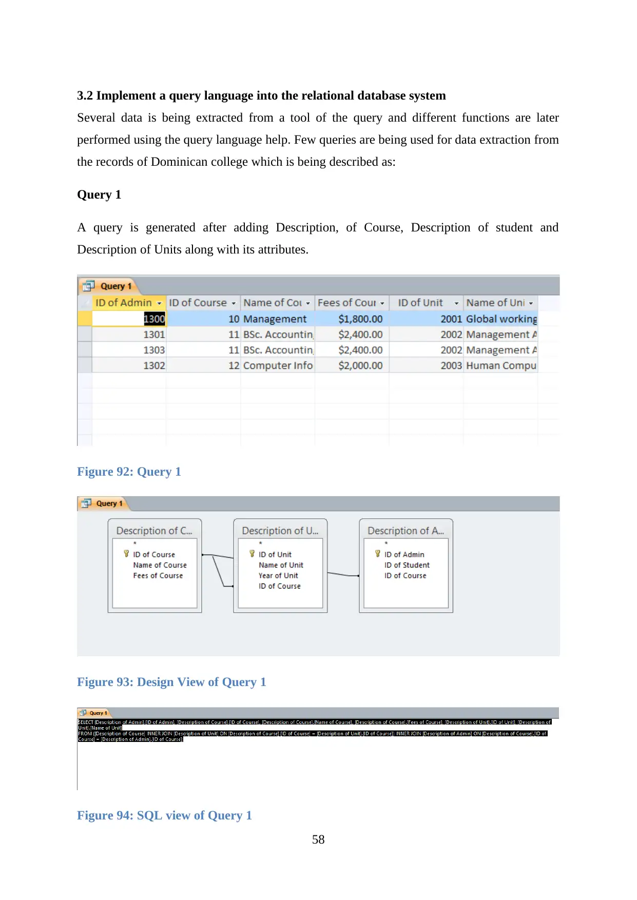
Figure 92: Query 1...................................................................................................................57
Figure 93: Design View of Query 1.........................................................................................57
Figure 94: SQL view of Query 1..............................................................................................57
Figure 95: Query 1 Report.......................................................................................................58
Figure 96: Query 2...................................................................................................................58
Figure 97: Design view of Query 2..........................................................................................58
Figure 98: SQL view of Query 2..............................................................................................59
Figure 99: Query 2 Report.......................................................................................................59
Figure 100: Query 3.................................................................................................................59
Figure 101: Design view of Query 3........................................................................................60
Figure 102: SQL view of Query 3............................................................................................60
Figure 103: Query 3 Report.....................................................................................................60
Figure 104: Query 4.................................................................................................................61
Figure 105: Design view of Query 4........................................................................................61
Figure 106: SQL view of Query 4............................................................................................61
Figure 107: Query 4 Report.....................................................................................................62
Figure 108: Query 5.................................................................................................................62
Figure 109: Design view of Query 5........................................................................................63
Figure 110: SQL view of Query 5............................................................................................63
Figure 111: Query 5 Report.....................................................................................................63
Figure 112: Query 6.................................................................................................................64
Figure 113: Design view of Query 6........................................................................................64
Figure 114: SQL view of Query 6............................................................................................64
Figure 115: Query 6 Report.....................................................................................................64
Figure 116: Query 7.................................................................................................................65
Figure 117: Design view of Query 7........................................................................................65
Figure 118: SQL view of Query 7............................................................................................65
Figure 119: Query 7 Report.....................................................................................................66
Figure 120: Query 8.................................................................................................................66
Figure 121: Design view of Query 8........................................................................................67
Figure 122: SQL view of Query 8............................................................................................67
Figure 123: Query 8 Report.....................................................................................................67
Figure 124: Query....................................................................................................................68
Figure 125: Query 1 Report.....................................................................................................68
Figure 126: Query 2.................................................................................................................69
Figure 127: Query 2 Report.....................................................................................................69
Figure 128: Query 3.................................................................................................................69
Figure 129: Query 3 Report.....................................................................................................70
Figure 130: Query 4.................................................................................................................70
5

Figure 131: Query 4 Report.....................................................................................................70
Figure 132: Query 5.................................................................................................................71
Figure 133: Query 5 Report.....................................................................................................71
Figure 134: Query 6.................................................................................................................72
Figure 135: Query 6 Report.....................................................................................................72
Figure 136: Query 7.................................................................................................................72
Figure 137: Query 7 Report.....................................................................................................73
Figure 138: Query 8.................................................................................................................73
Figure 139: Query 8 Report.....................................................................................................74
Figure 140: Validation Applied in Test case 1.........................................................................80
Figure 141: Validation Applied in Test case 2.........................................................................81
Figure 142: Validation Applied in Test case 3.........................................................................82
Figure 143: Validation Applied in Test case 4.........................................................................83
Figure 144: Validation Applied in Test case 5.........................................................................84
Figure 145: Validation Applied in Test case 6.........................................................................85
Figure 146: Validation Applied in Test case 7.........................................................................86
Figure 147: Validation Applied in Test case 8.........................................................................87
Figure 148: Validation Applied in Test case 9.........................................................................88
Figure 149: Description of Academic Manager From.............................................................89
Figure 150: Description of Admin From.................................................................................89
Figure 151: Description of Campus From...............................................................................90
Figure 152: Description of Course From.................................................................................90
Figure 153: Description of Lecturer From...............................................................................91
Figure 154: Description of Student From................................................................................91
Figure 155: Description of Unit From.....................................................................................92
Figure 156: Validation Applied in Test case 1.........................................................................93
Figure 157: Validation Applied in Test case 2.........................................................................94
Figure 158: Validation Applied in Test case 3.........................................................................94
Figure 159: Validation Applied in Test case 4.........................................................................95
Figure 160: Validation Applied in Test case 5.........................................................................95
Figure 161: Validation Applied in Test case 6.........................................................................96
Figure 162: Validation Applied in Test case 7.........................................................................96
Figure 163: Validation Applied in Test case 8.........................................................................97
Figure 164: Validation Applied in Test case 9.........................................................................97
6
Introduction
The entire analysis of the database is a procedure so as to design a database in respect to the
requirements and desires of the user. The created database is being used in order to handle the
data along with a reduction in the redundancy of the data. The database normally presents
different approaches in which it can be created that are data related models and dictionary of
data etc. The database development is normally started with the generation of various
diagrams that are both logical and conceptual based relationship.
The college named as Dominican wants to develop a database for it using the MS Access.
The given college is located in a city of New York. This college has overall three campuses
that have various courses associated that are being taught to all the learners. The database and
its report are being developed to meet all the desires of the user. The development of the
database begins with the table’s creation where users analyse those data which are being
stored. In database further phase various forms are developed that allows users to put their
data which is valuable. In the final stage, several queries are being created depending on
desires of data so that they can filter data.
7
Paraphrase This Document
Need a fresh take? Get an instant paraphrase of this document with our AI Paraphraser
LO1 Understand data models and database technologies
1.1 Critically compare different data models and schemas
A database model is known as representation, layout or logical structure of the database and it
tells us that how will data be processed, stored and managed within it. So it is helpful for
designing the database. The database has many models. Which are:
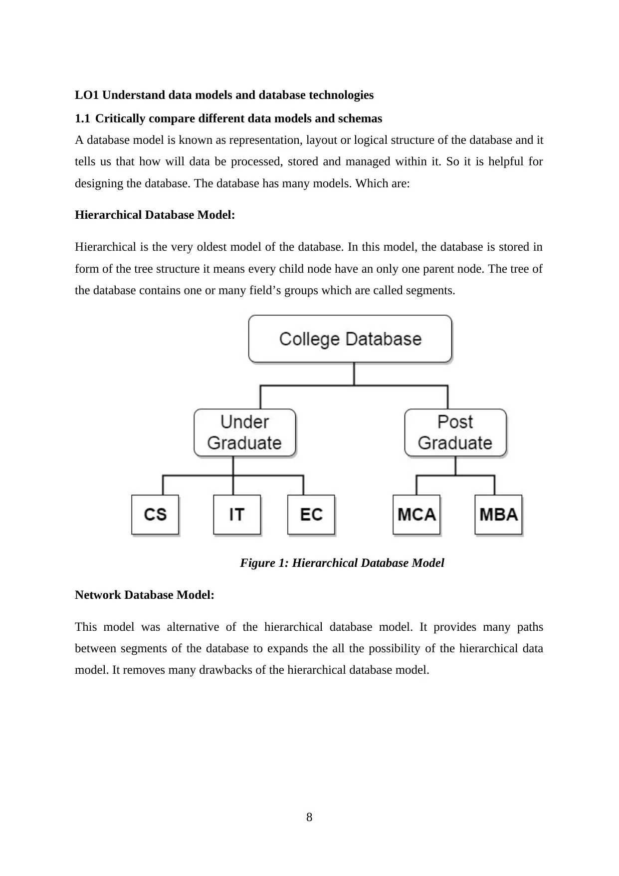
Hierarchical Database Model:
Hierarchical is the very oldest model of the database. In this model, the database is stored in
form of the tree structure it means every child node have an only one parent node. The tree of
the database contains one or many field’s groups which are called segments.
Figure 1: Hierarchical Database Model
Network Database Model:
This model was alternative of the hierarchical database model. It provides many paths
between segments of the database to expands the all the possibility of the hierarchical data
model. It removes many drawbacks of the hierarchical database model.
8

Figure 2: Network Database Model
Relational Database Model:
In relational database model, all the database represents in form of the two-dimensional tables
which is called relations. In the relational table, each row should have a unique key and this
field called a tuple. Column’s data entity called as attributes.
For Example, College table has a primary key which is Batch_Year and it has a second key
which is Course_ID and Student_ID.
Figure 3: Relational Database Model
9

Object-oriented Database Model:
In object-oriented database model, we can define our database access methods these methods
are used to manipulate and represent the database. So object-oriented database model
maintains and stores the database.
Figure 4: Object-oriented Database Model
Comparisons between Database Models:
Comparison Hierarchical Network Relational Object Oriented
Data Structure Use tree
structure for
store database
Use network
form structure
for store
database
Use table
structure for
store database
Use objects
structure to store
database
Relationship One to one and
one to many
One to one, one
to many and
many to many
One to one and
one to many
Many to many
Data types
support
It supports all
types of data
It supports all
types of data
It supports only
primitive data
It supports all
basics of
primitive data
Mathematical
support
It doesn’t
support
It doesn’t
support
It supports
mathematical
functions
It supports only
user-defined
methods and
functions.
Advantage The database
can be updated
It provides the
multiple paths
It provides the
flexibility to
It can easily
support numbers
10
Secure Best Marks with AI Grader
Need help grading? Try our AI Grader for instant feedback on your assignments.
and retrieval
easily.
for the database
structure.
change the
database.
of servers.
Disadvantage We can’t be
modified data
structure.
It is difficult to
maintain all
links
It is difficult to
navigate
It has a slow
performance
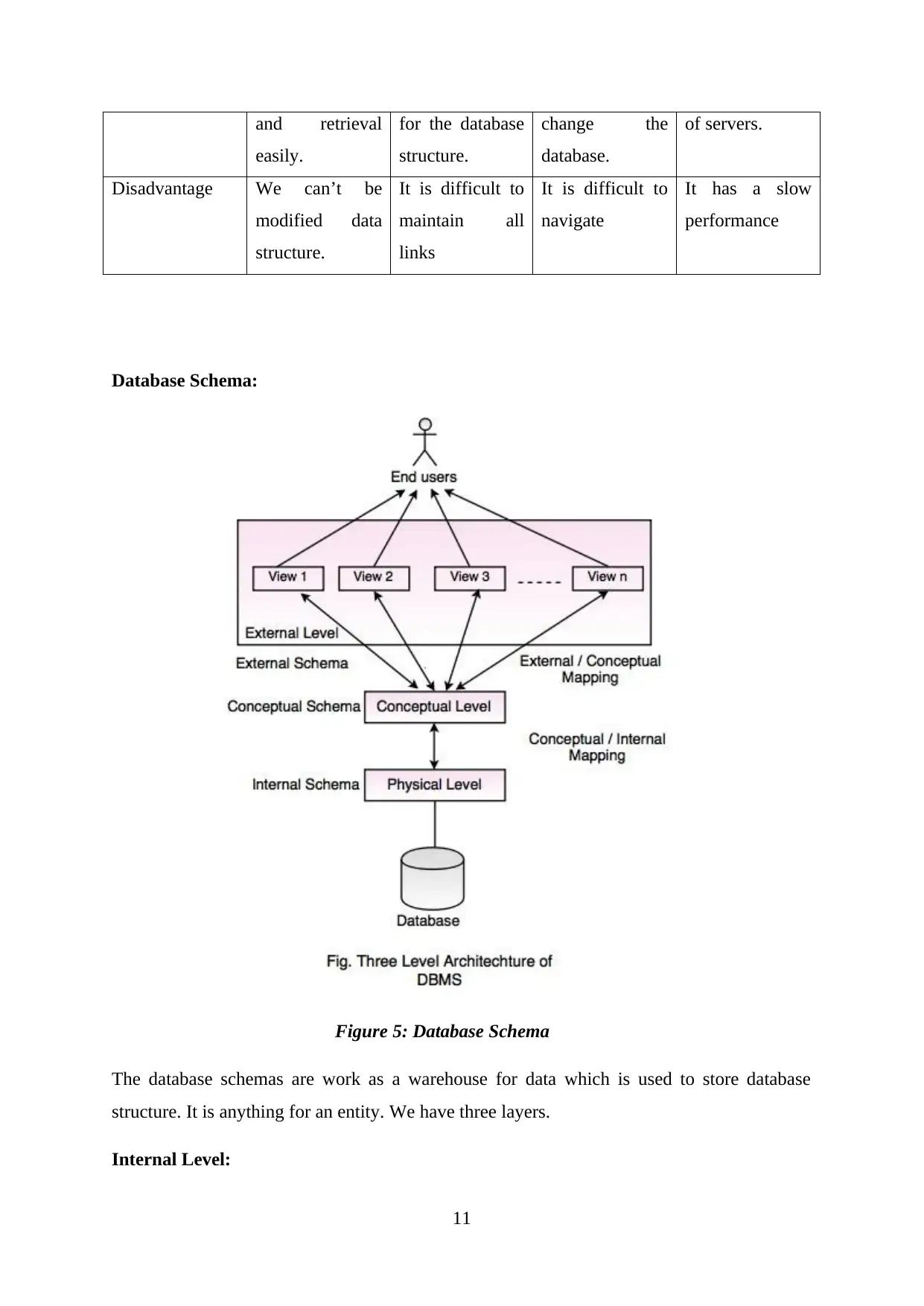
Database Schema:
Figure 5: Database Schema
The database schemas are work as a warehouse for data which is used to store database
structure. It is anything for an entity. We have three layers.
Internal Level:
11

It describes the internal storage of data’s structure in the database.
It is used to store data in form of bits at the lowest level.
It can use to view data in form of files at the highest level.
Conceptual Level:
It describes the structure of the database for grouping the users.
This schema is used to generate the external records.
It can hide internal data.
It represents the entire data of the database.
External Level:
It is used to view data by particular end users.
The external level is nearest to end user.
External level includes no. of views of the user.
12
1.2 Critically discuss the benefits and limitations of different database technologies
File-based System:
Benefits:
We can take automatic and faster back-up of the database which is stored in form of
files.
We can store the data in a compact form
It provides techniques so we can easily retrieve the data in an efficient manner.
We can easily edit the data information which is stored in the files.
We can control the access of data remotely.
We can share data with multiple users which are stored in form files.
Limitation:
Due to data inconsistency, it can be possible that data will not the inconsistent state.
Due to data isolation, we can’t share the data which is saved in another format and
share to another format application.
It can possibility that same data can be stored in different files. Which is created data
redundancy and memory wastage?
Each user can access the data according to his need so it generates the security issues.
Relational Database:
Benefits:
We can easily revise the data information because tables contain the columns and
rows.
In this numbers of tables are linked so we can easily manipulate and extract the data
information.
By moving complex attributes, Security authorization and control can be easily
implemented.
Data independence can be easily achieved by using normalized structure.
So using relational database system there is no chance of ambiguity.
Limitation:
All database store in the physical storage which increases the problems in database
13
Paraphrase This Document
Need a fresh take? Get an instant paraphrase of this document with our AI Paraphraser
Database store in a relational so it takes a time to extract data from files.
When we use a number of tables and establish a relationship between tables are large.
Then it leads to performance issues.
Multimedia Database:
Benefits:
It is a very user-friendly database system. We don’t need a number of users. You can
sit and watch the demo and read the text.
This database is very interactive and comprehensive.
This database is flexible.
This system can have a variety of viewers and can share information from one to
many at a time.
Limitation:
It takes more for compilation.
It is expensive.
Information can overload.
Object-Oriented Database:
Benefits:
It reduces maintenance problems
It improves flexibility and reliability.
It can reuse the code.
Limitation:
It is not technology
It is not accepted by vendors.
Cloud Computing:
Benefits:
It is cost saving.
It is reliable.
It can easily manage.
14
Limitation:
It is lack secure.
Limited control because it entirely monitors and controls by the service provider.
Distributed Database:
Benefits:
It is robust in nature.
It can grow easily.
Communication cost low.
Limitation:
Complex implementation.
Difficult to handle deadlock.
Data Warehousing:
Benefits:
Data access from multiple sources.
Saves money and time
Generate high revenue.
Limitation:
Report work is extra.
Data inflexibility.
15

1.3 Analyze different approaches to database design
Top-Down:
This approach deals with real-world objects. It starts with a general idea and then we work to
more specific. It represents the relationship between attribute and entities.
Roles:
For analyzing aggregation risk.
For measures modifications in economic variables.
Figure 6: A Top-Down design approach
Bottom-Up:
This approach starts with specific facts and moves to general. This approach totally depends
on individual stocks.
Roles:
For management and performance.
For mathematical models.
16
Secure Best Marks with AI Grader
Need help grading? Try our AI Grader for instant feedback on your assignments.
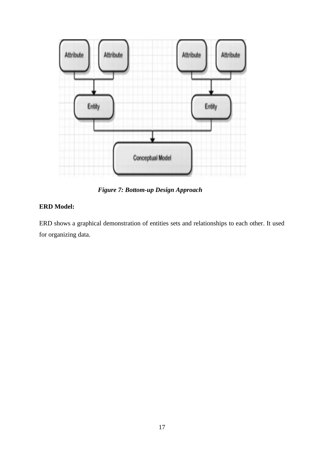
Figure 7: Bottom-up Design Approach
ERD Model:
ERD shows a graphical demonstration of entities sets and relationships to each other. It used
for organizing data.
17
ERD Model:
ERD shows a graphical demonstration of entities sets and relationships to each other. It used
for organizing data.
17
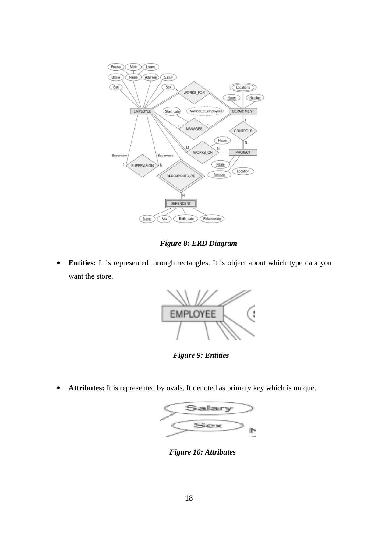
Figure 8: ERD Diagram
Entities: It is represented through rectangles. It is object about which type data you
want the store.
Figure 9: Entities
Attributes: It is represented by ovals. It denoted as primary key which is unique.
Figure 10: Attributes
18
Entities: It is represented through rectangles. It is object about which type data you
want the store.
Figure 9: Entities
Attributes: It is represented by ovals. It denoted as primary key which is unique.
Figure 10: Attributes
18
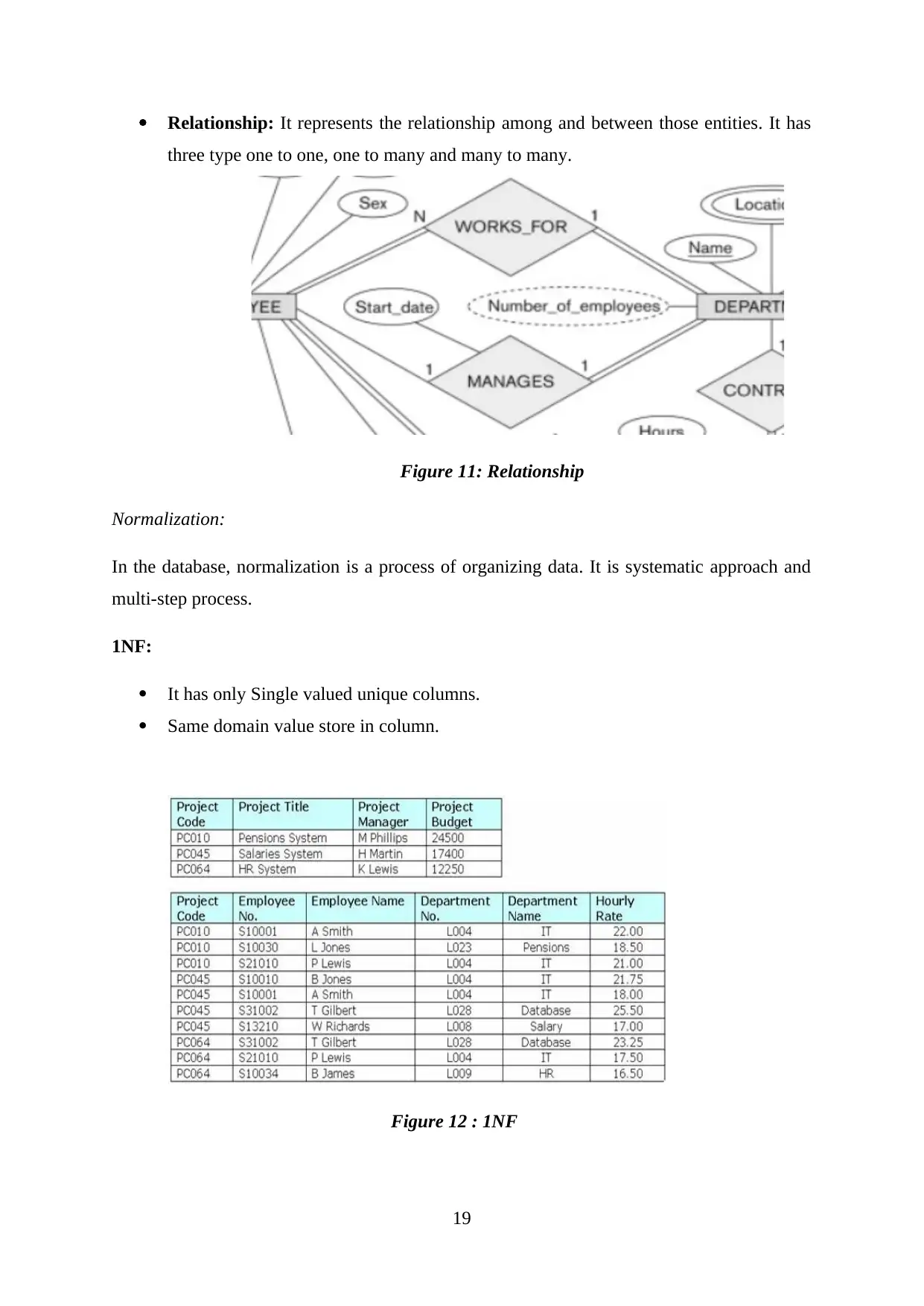
Relationship: It represents the relationship among and between those entities. It has
three type one to one, one to many and many to many.
Figure 11: Relationship
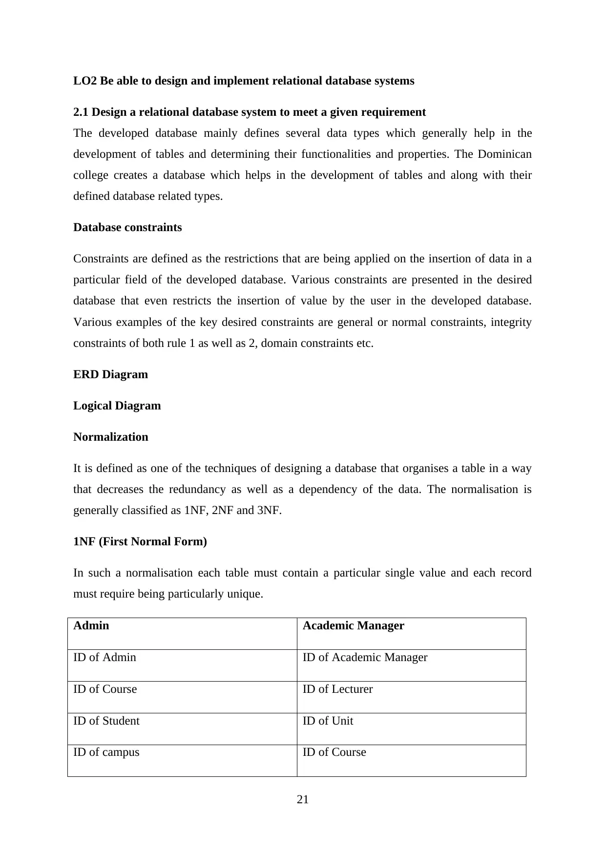
Normalization:
In the database, normalization is a process of organizing data. It is systematic approach and
multi-step process.
1NF:
It has only Single valued unique columns.
Same domain value store in column.
Figure 12 : 1NF
19
Paraphrase This Document
Need a fresh take? Get an instant paraphrase of this document with our AI Paraphraser

2NF:
It must be in 1NF.
It must not have a fractional dependency.
Figure 13: 2NF
3NF:
It must be in 2NF.
It must not have a transitive dependency.
Figure 14: 3NF
20
It must be in 1NF.
It must not have a fractional dependency.
Figure 13: 2NF
3NF:
It must be in 2NF.
It must not have a transitive dependency.
Figure 14: 3NF
20
LO2 Be able to design and implement relational database systems
2.1 Design a relational database system to meet a given requirement
The developed database mainly defines several data types which generally help in the
development of tables and determining their functionalities and properties. The Dominican
college creates a database which helps in the development of tables and along with their
defined database related types.
Database constraints
Constraints are defined as the restrictions that are being applied on the insertion of data in a
particular field of the developed database. Various constraints are presented in the desired
database that even restricts the insertion of value by the user in the developed database.
Various examples of the key desired constraints are general or normal constraints, integrity
constraints of both rule 1 as well as 2, domain constraints etc.
ERD Diagram
Logical Diagram
Normalization
It is defined as one of the techniques of designing a database that organises a table in a way
that decreases the redundancy as well as a dependency of the data. The normalisation is
generally classified as 1NF, 2NF and 3NF.
1NF (First Normal Form)
In such a normalisation each table must contain a particular single value and each record
must require being particularly unique.
Admin Academic Manager
ID of Admin ID of Academic Manager
ID of Course ID of Lecturer
ID of Student ID of Unit
ID of campus ID of Course
21
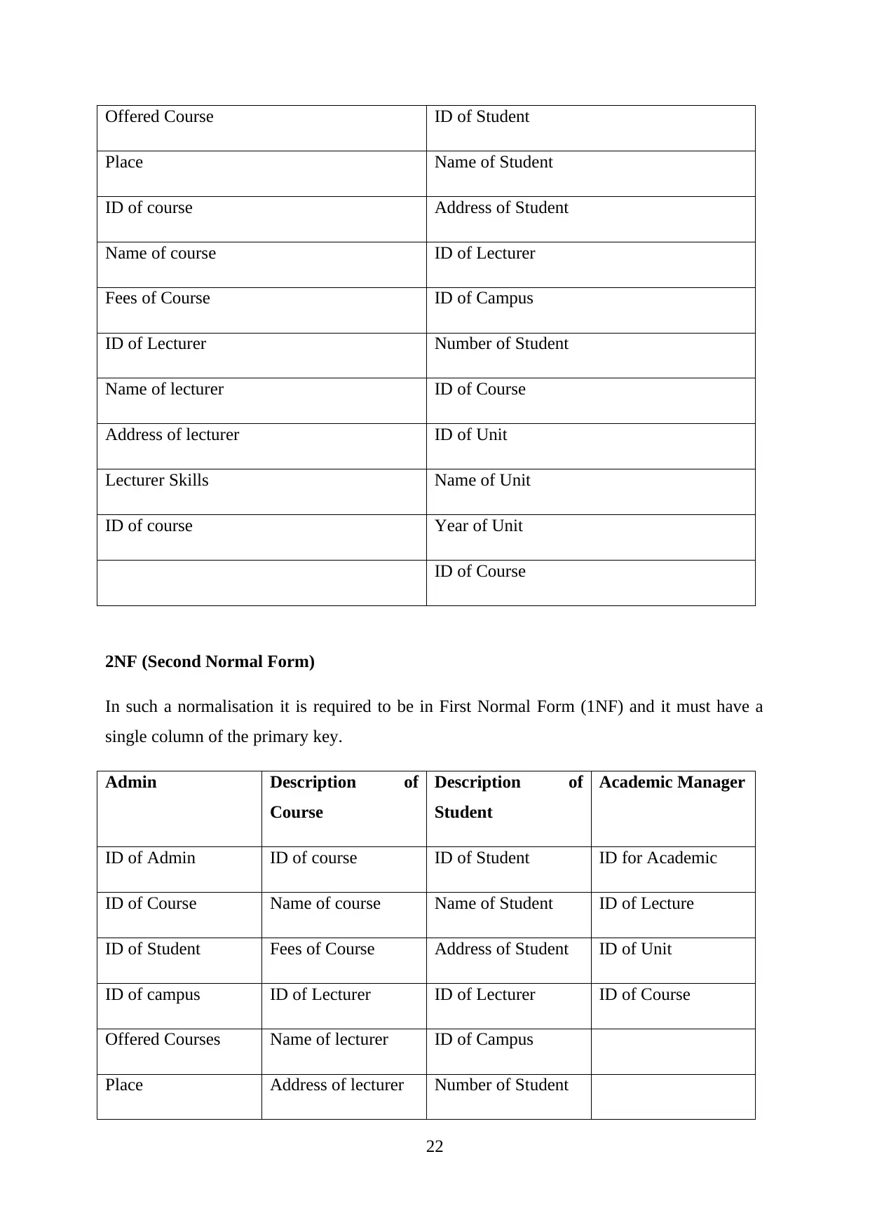
Offered Course ID of Student
Place Name of Student
ID of course Address of Student
Name of course ID of Lecturer
Fees of Course ID of Campus
ID of Lecturer Number of Student
Name of lecturer ID of Course
Address of lecturer ID of Unit
Lecturer Skills Name of Unit
ID of course Year of Unit
ID of Course
2NF (Second Normal Form)
In such a normalisation it is required to be in First Normal Form (1NF) and it must have a
single column of the primary key.
Admin Description of
Course
Description of
Student
Academic Manager
ID of Admin ID of course ID of Student ID for Academic
ID of Course Name of course Name of Student ID of Lecture
ID of Student Fees of Course Address of Student ID of Unit
ID of campus ID of Lecturer ID of Lecturer ID of Course
Offered Courses Name of lecturer ID of Campus
Place Address of lecturer Number of Student
22
Secure Best Marks with AI Grader
Need help grading? Try our AI Grader for instant feedback on your assignments.
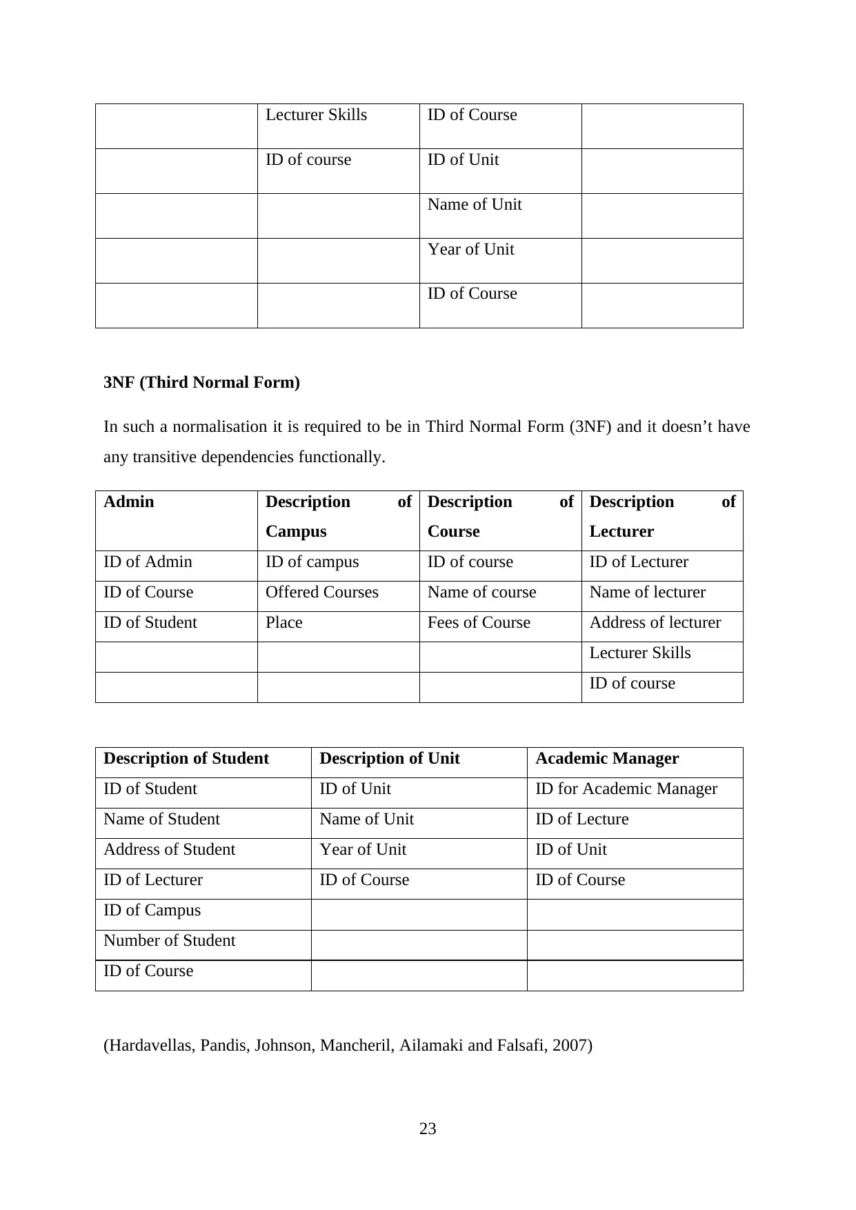
Lecturer Skills ID of Course
ID of course ID of Unit
Name of Unit
Year of Unit
ID of Course
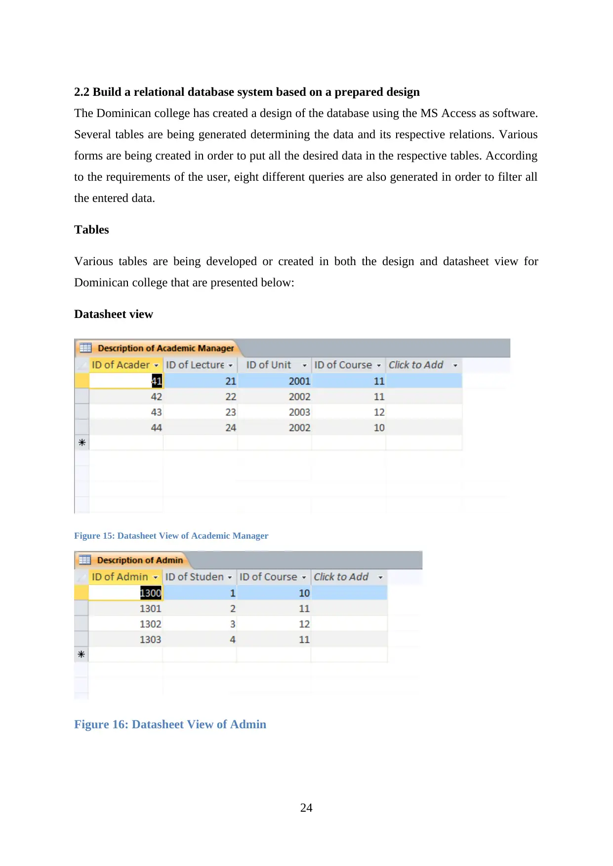
3NF (Third Normal Form)
In such a normalisation it is required to be in Third Normal Form (3NF) and it doesn’t have
any transitive dependencies functionally.
Admin Description of
Campus
Description of
Course
Description of
Lecturer
ID of Admin ID of campus ID of course ID of Lecturer
ID of Course Offered Courses Name of course Name of lecturer
ID of Student Place Fees of Course Address of lecturer
Lecturer Skills
ID of course
Description of Student Description of Unit Academic Manager
ID of Student ID of Unit ID for Academic Manager
Name of Student Name of Unit ID of Lecture
Address of Student Year of Unit ID of Unit
ID of Lecturer ID of Course ID of Course
ID of Campus
Number of Student
ID of Course
(Hardavellas, Pandis, Johnson, Mancheril, Ailamaki and Falsafi, 2007)
23
2.2 Build a relational database system based on a prepared design
The Dominican college has created a design of the database using the MS Access as software.
Several tables are being generated determining the data and its respective relations. Various
forms are being created in order to put all the desired data in the respective tables. According
to the requirements of the user, eight different queries are also generated in order to filter all
the entered data.
Tables
Various tables are being developed or created in both the design and datasheet view for
Dominican college that are presented below:
Datasheet view
Figure 15: Datasheet View of Academic Manager
Figure 16: Datasheet View of Admin
24

Figure 17: Datasheet View of Campus
Figure 18: Datasheet View of Course
Figure 19: Datasheet View of Lecturer
25
Figure 18: Datasheet View of Course
Figure 19: Datasheet View of Lecturer
25
Paraphrase This Document
Need a fresh take? Get an instant paraphrase of this document with our AI Paraphraser
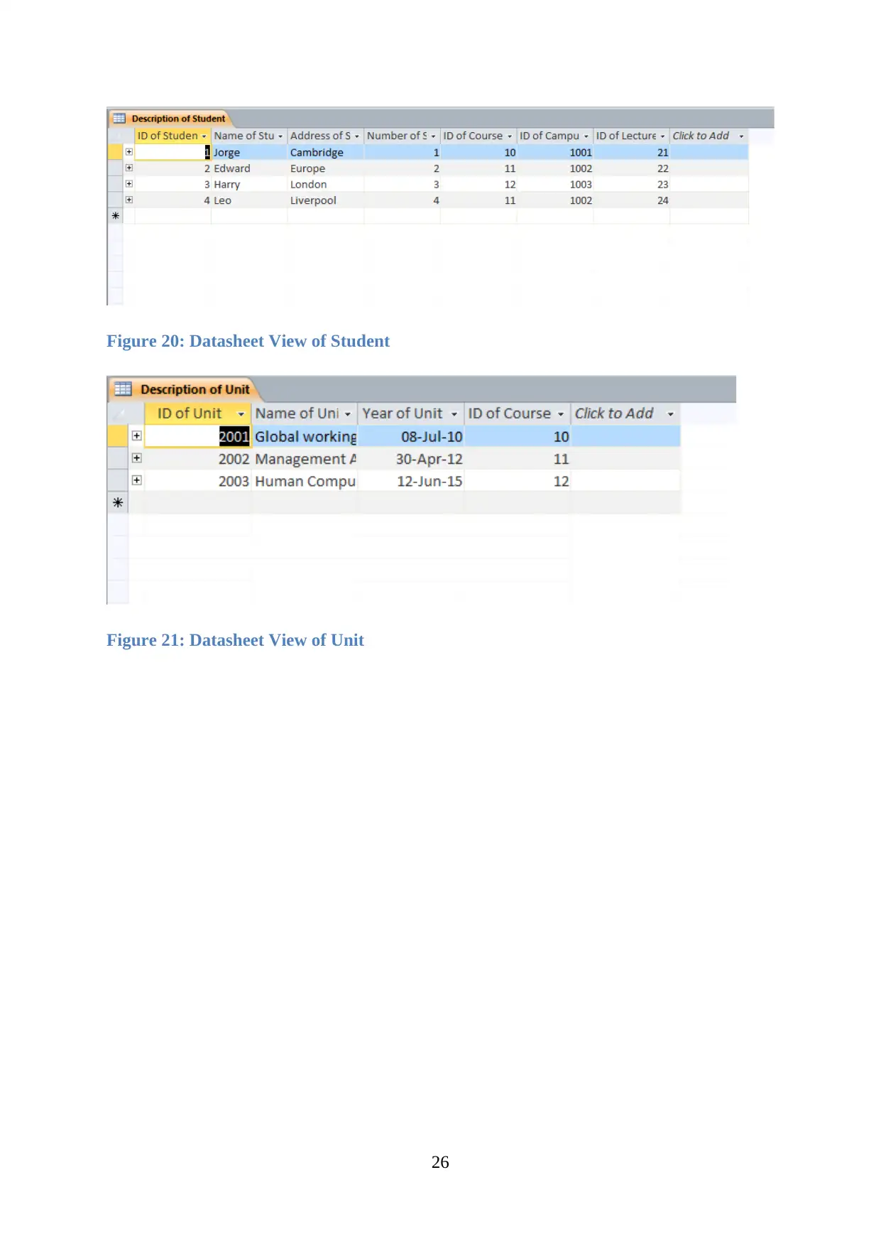
Figure 20: Datasheet View of Student
Figure 21: Datasheet View of Unit
26
Figure 21: Datasheet View of Unit
26
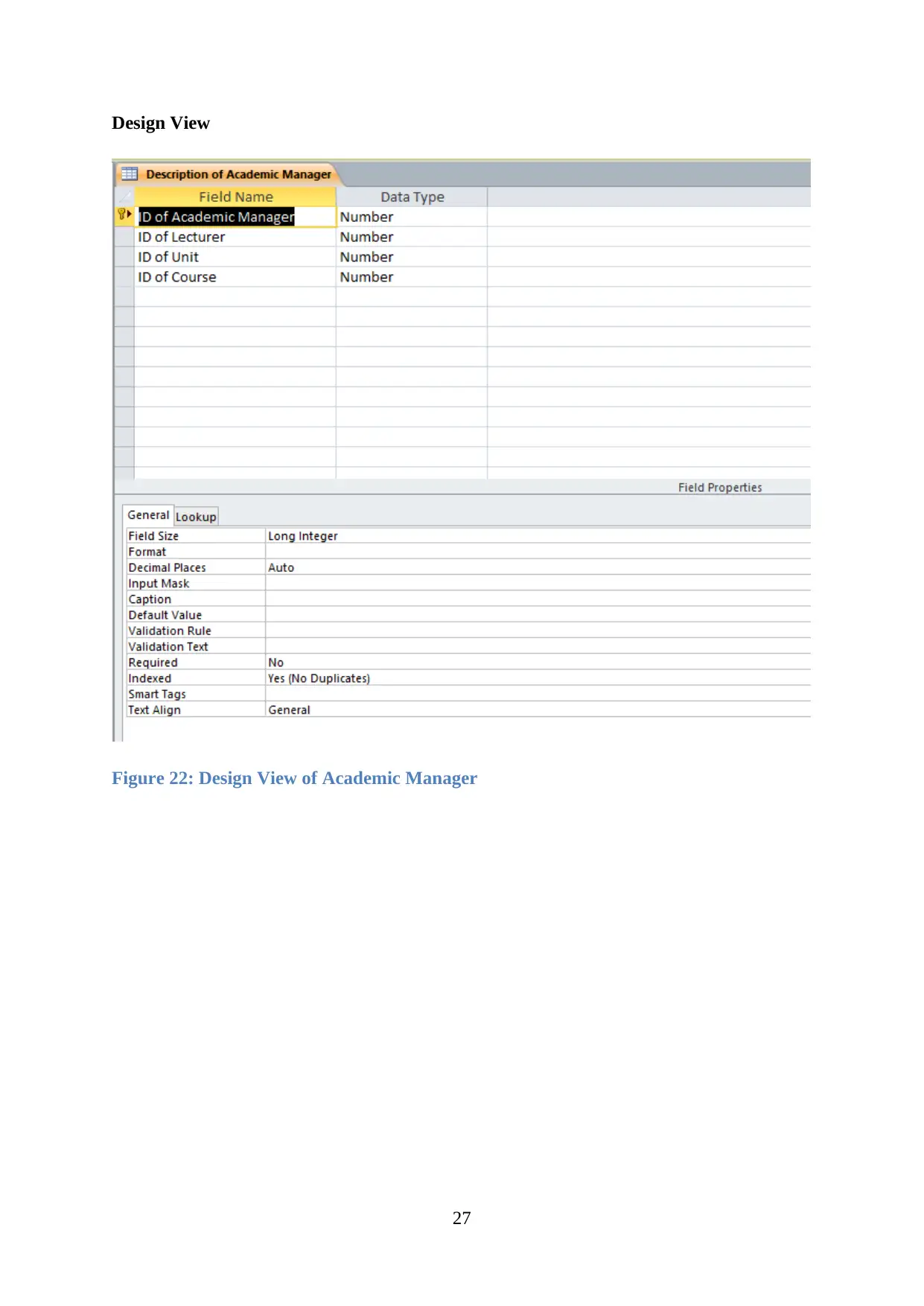
Design View
Figure 22: Design View of Academic Manager
27
Figure 22: Design View of Academic Manager
27

Figure 23: Design View of Admin
28
28
Secure Best Marks with AI Grader
Need help grading? Try our AI Grader for instant feedback on your assignments.
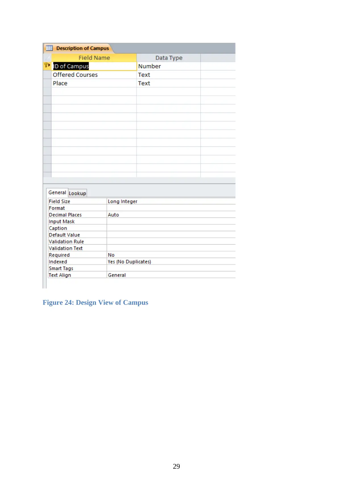
Figure 24: Design View of Campus
29
29
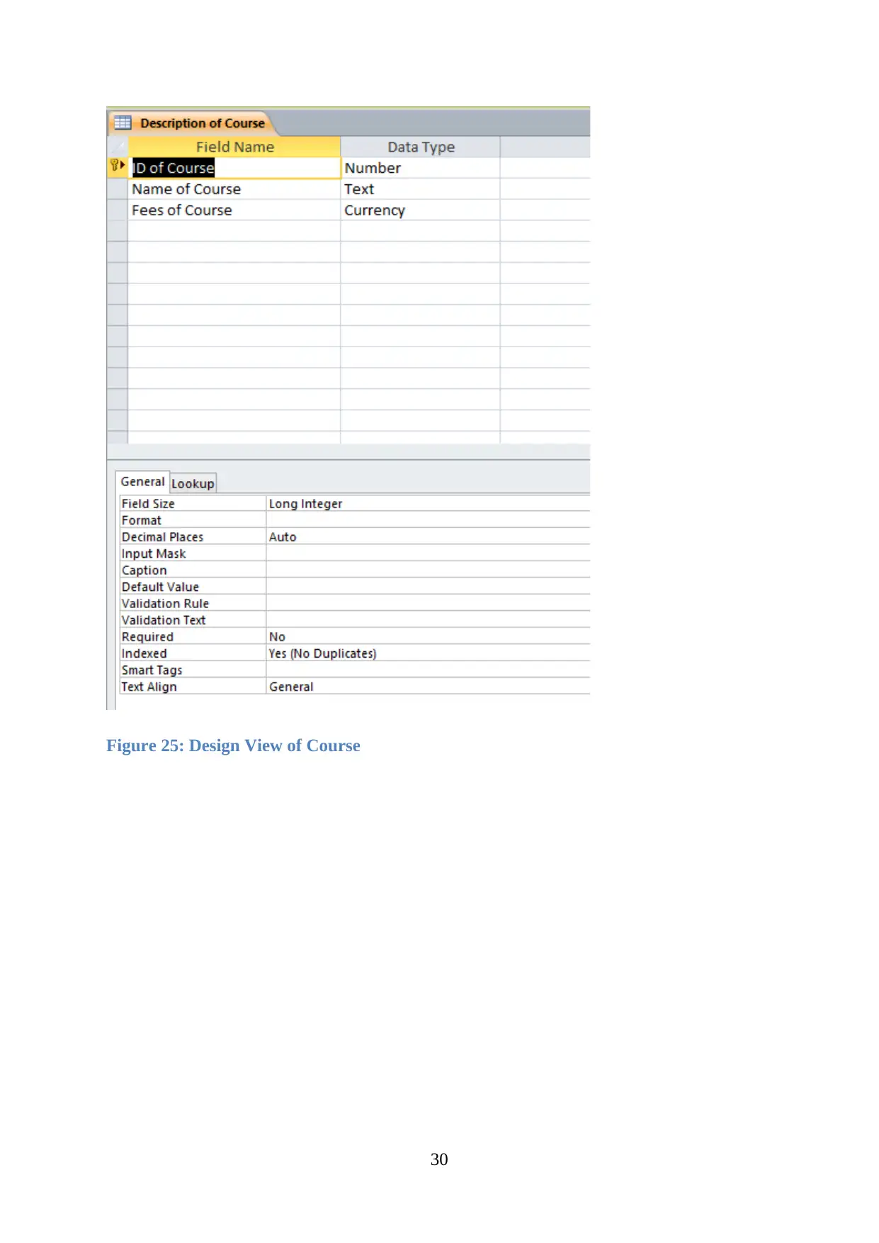
Figure 25: Design View of Course
30
30
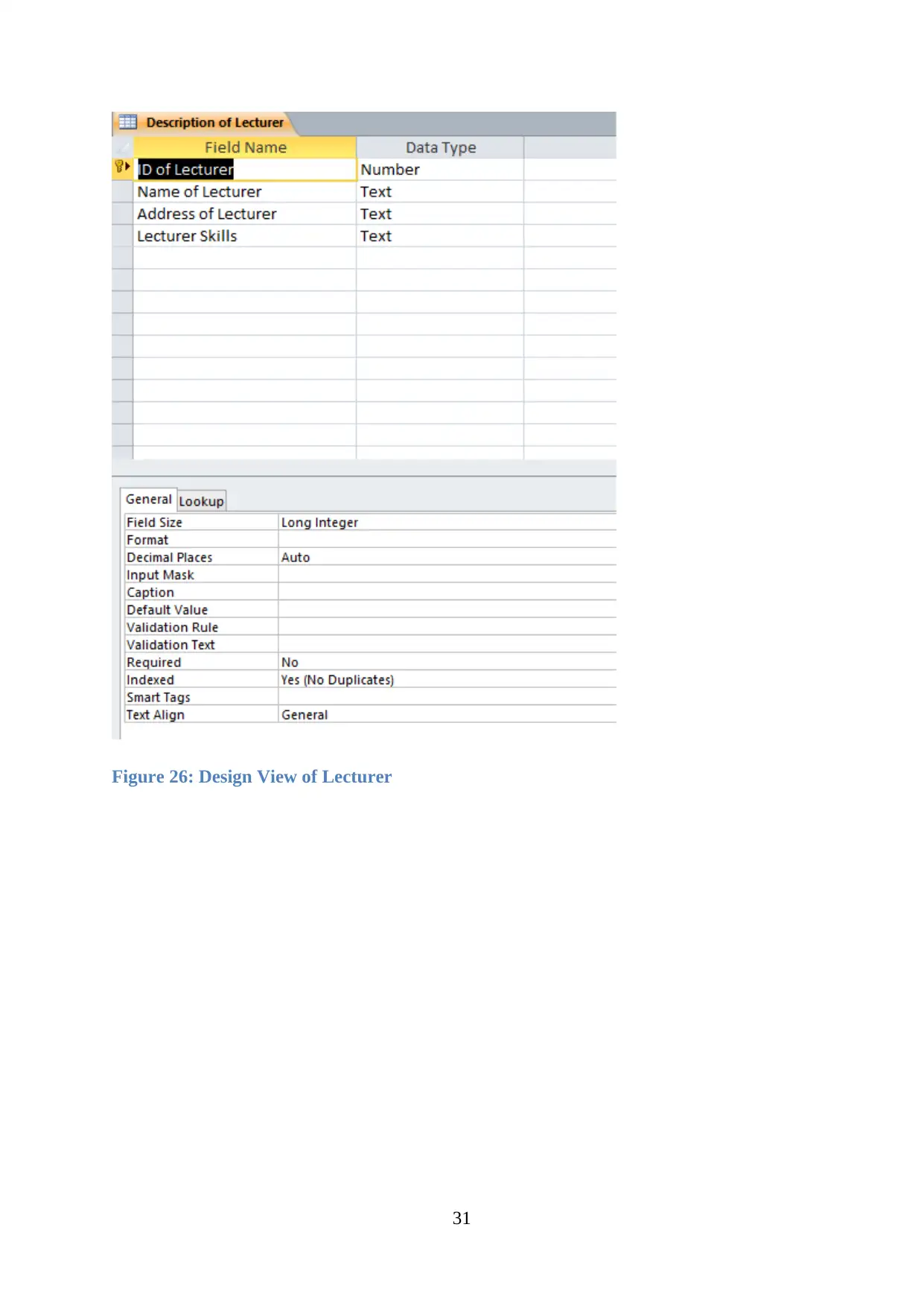
Figure 26: Design View of Lecturer
31
31
Paraphrase This Document
Need a fresh take? Get an instant paraphrase of this document with our AI Paraphraser

Figure 27: Design View of Student
32
32
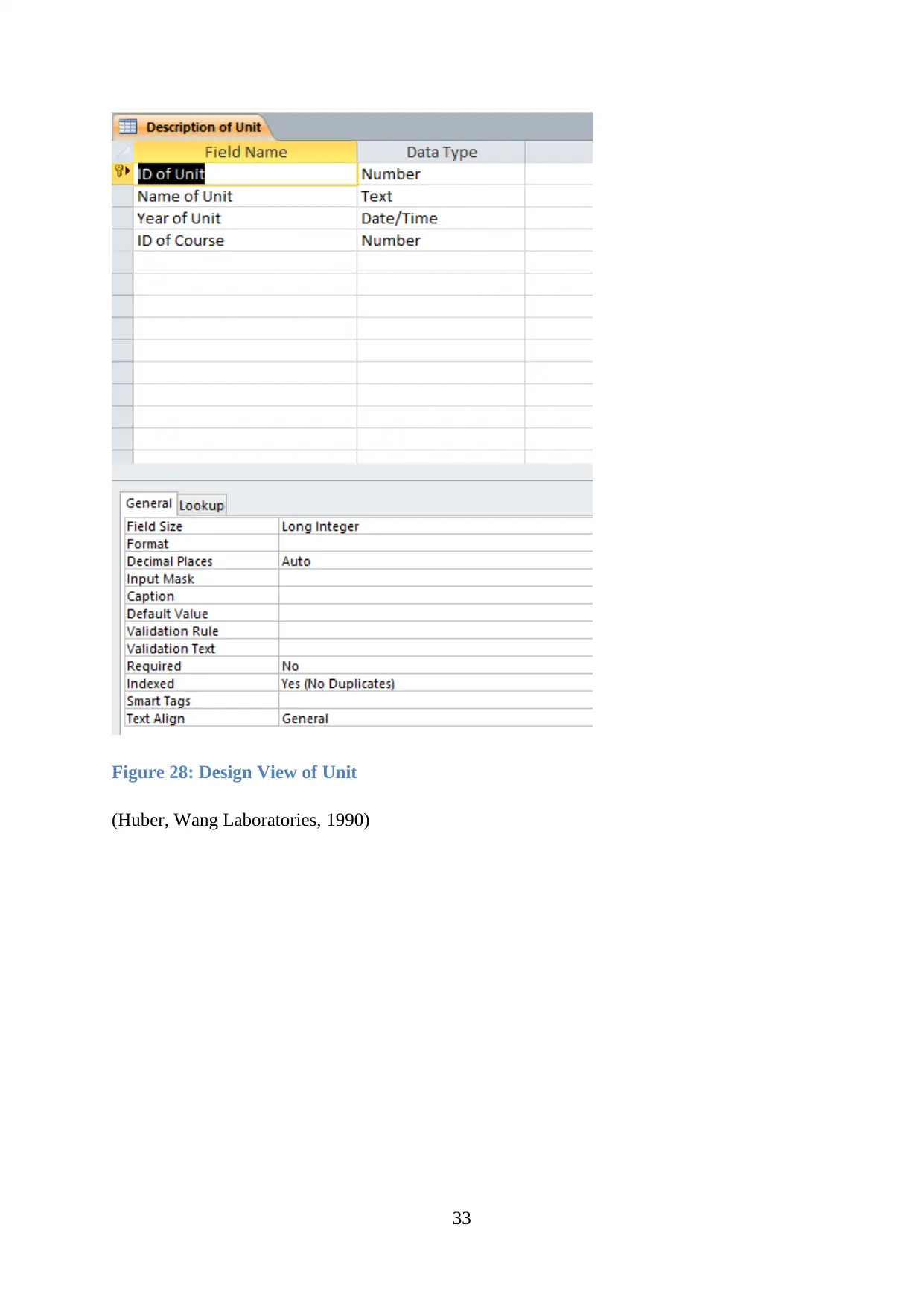
Figure 28: Design View of Unit
(Huber, Wang Laboratories, 1990)
33
(Huber, Wang Laboratories, 1990)
33

Data Dictionary
Table Name Attributes Data Type PK/FK
Description of Lecturer ID of Lecturer Number PK
Name of lecturer Text FK
Address of lecturer Text FK
Lecturer Skills Text FK
ID of course Number FK
Description of Unit ID of Unit Number PK
Name of Unit Text FK
Year of Unit Date/Time FK
ID of Course Number FK
Admin ID of Admin Number PK
ID of Course Number FK
ID of Student Number FK
Description of Course ID of course Number PK
Name of course Text FK
Fees of Course Currency FK
Description of Campus ID of campus Number PK
Offered Courses Text FK
Place Text FK
Academic Manager ID for Academic Number PK
ID of Lecture Number FK
ID of Unit Number FK
ID of Courses Number FK
Description of Student ID of Student Number PK
Name of Student Text FK
Address of Student Text FK
ID of Lecturer Number FK
34
Secure Best Marks with AI Grader
Need help grading? Try our AI Grader for instant feedback on your assignments.

ID of Campus Number FK
Number of Student Number FK
ID of Course Number FK
35
Number of Student Number FK
ID of Course Number FK
35
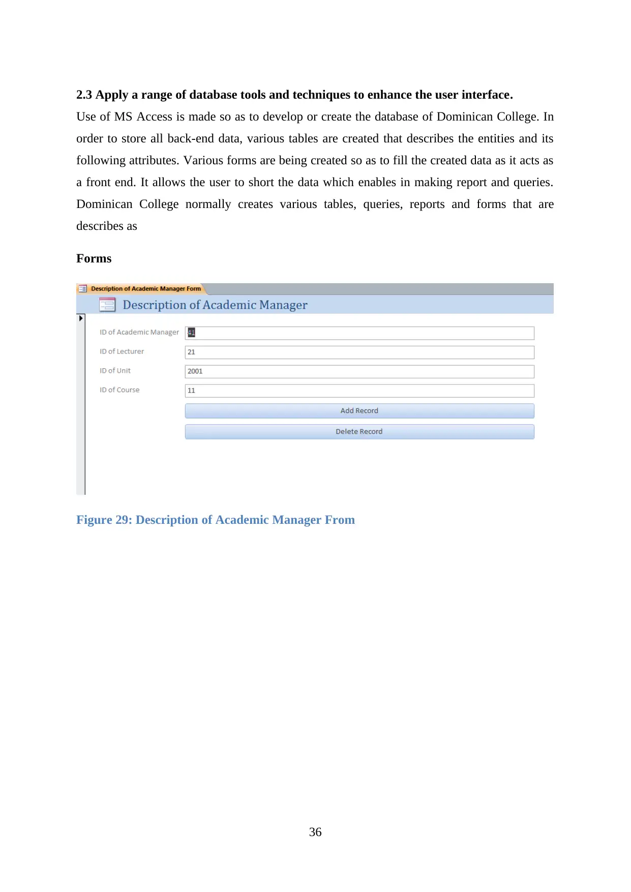
2.3 Apply a range of database tools and techniques to enhance the user interface.
Use of MS Access is made so as to develop or create the database of Dominican College. In
order to store all back-end data, various tables are created that describes the entities and its
following attributes. Various forms are being created so as to fill the created data as it acts as
a front end. It allows the user to short the data which enables in making report and queries.
Dominican College normally creates various tables, queries, reports and forms that are
describes as
Forms
Figure 29: Description of Academic Manager From
36

Figure 30: Description of Admin From
Figure 31: Description of Campus From
37
Figure 31: Description of Campus From
37
Paraphrase This Document
Need a fresh take? Get an instant paraphrase of this document with our AI Paraphraser
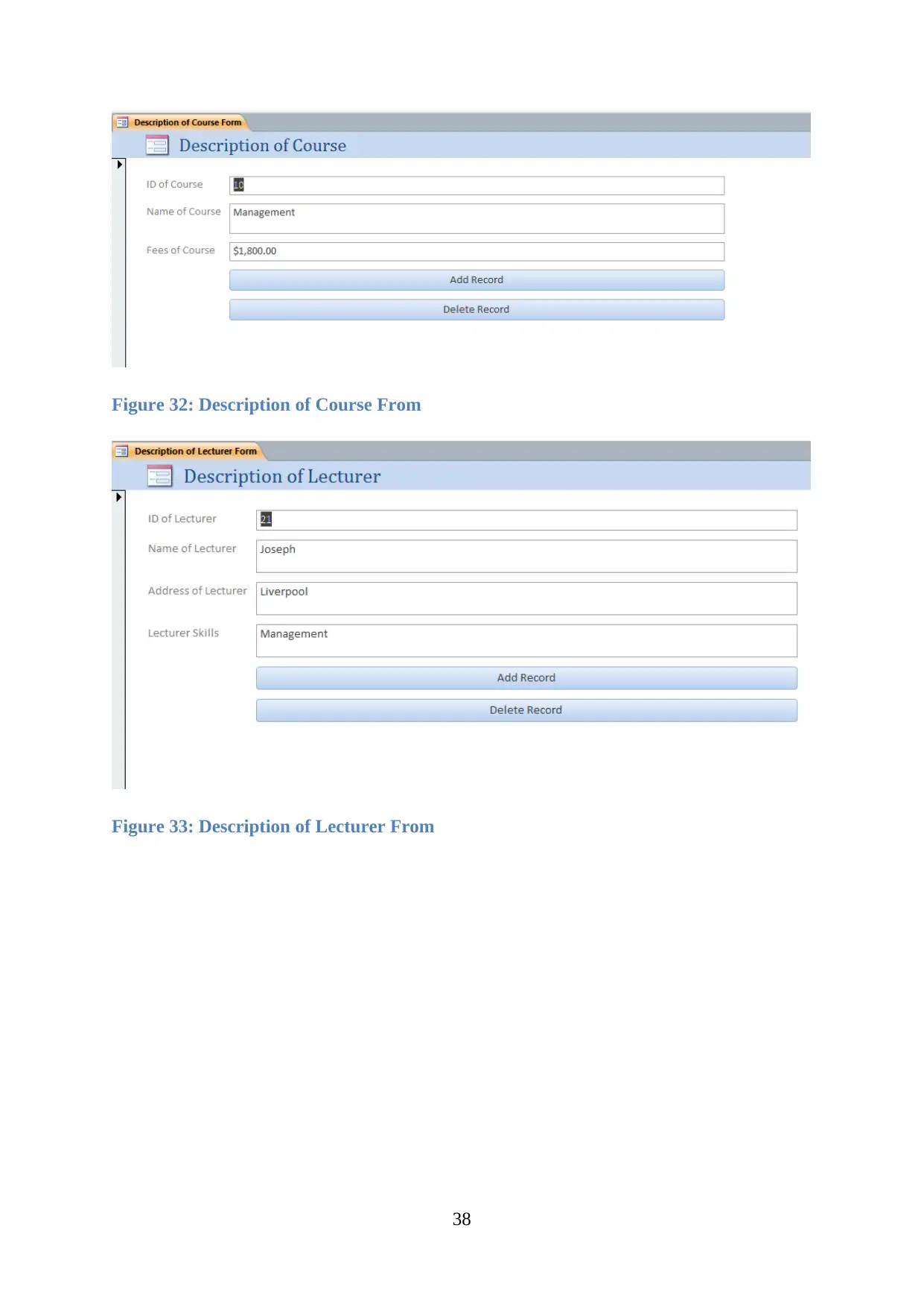
Figure 32: Description of Course From
Figure 33: Description of Lecturer From
38
Figure 33: Description of Lecturer From
38

Figure 34: Description of Student From
Figure 35: Description of Unit From
Tables
Datasheet view
39
Figure 35: Description of Unit From
Tables
Datasheet view
39
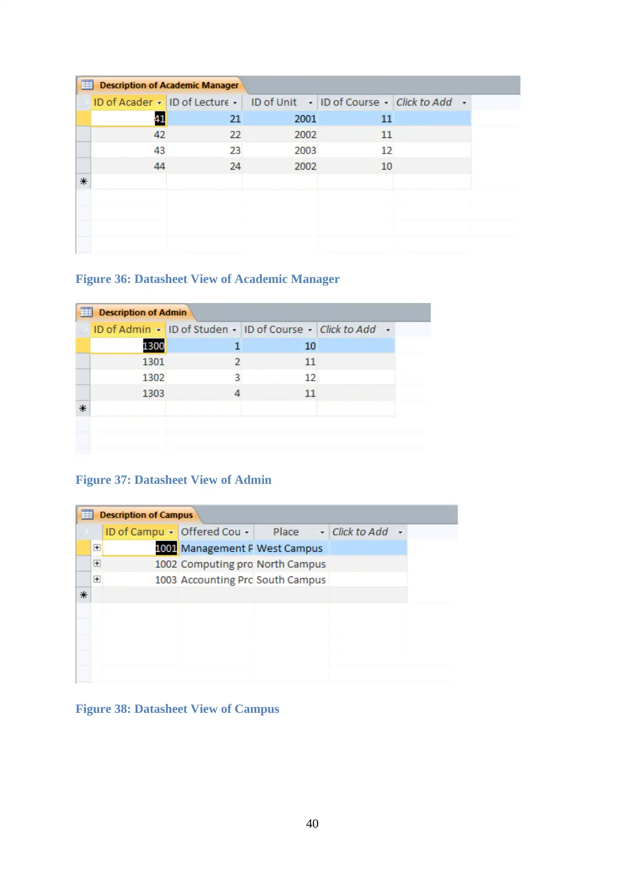
Figure 36: Datasheet View of Academic Manager
Figure 37: Datasheet View of Admin
Figure 38: Datasheet View of Campus
40
Figure 37: Datasheet View of Admin
Figure 38: Datasheet View of Campus
40
Secure Best Marks with AI Grader
Need help grading? Try our AI Grader for instant feedback on your assignments.
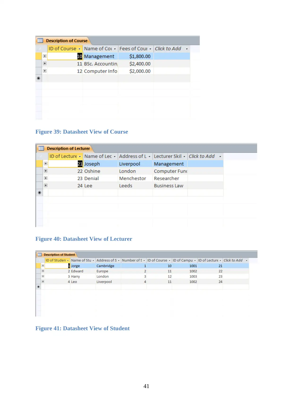
Figure 39: Datasheet View of Course
Figure 40: Datasheet View of Lecturer
Figure 41: Datasheet View of Student
41
Figure 40: Datasheet View of Lecturer
Figure 41: Datasheet View of Student
41
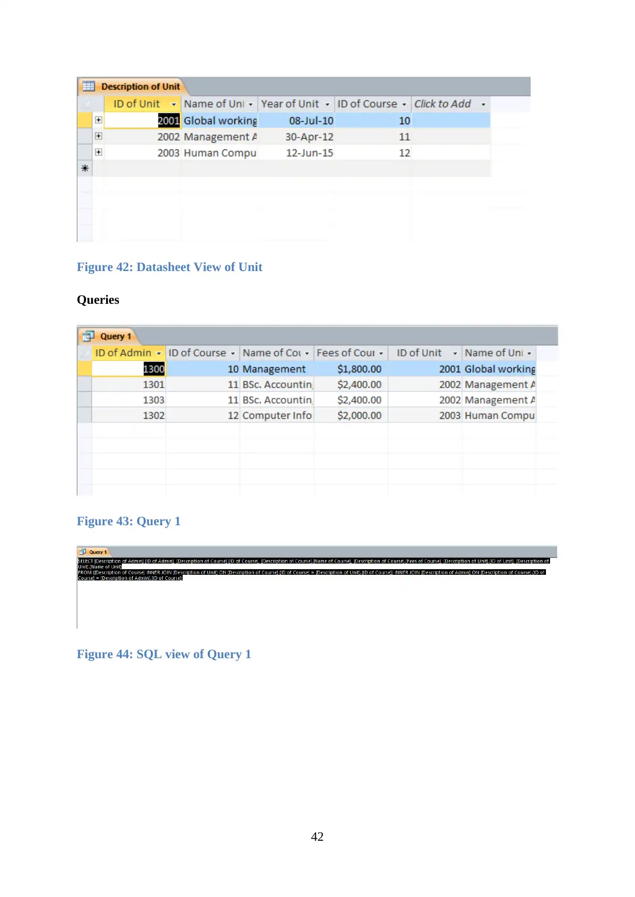
Figure 42: Datasheet View of Unit
Queries
Figure 43: Query 1
Figure 44: SQL view of Query 1
42
Queries
Figure 43: Query 1
Figure 44: SQL view of Query 1
42
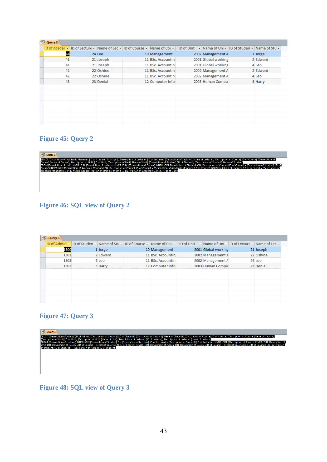
Figure 45: Query 2
Figure 46: SQL view of Query 2
Figure 47: Query 3
Figure 48: SQL view of Query 3
43
Figure 46: SQL view of Query 2
Figure 47: Query 3
Figure 48: SQL view of Query 3
43
Paraphrase This Document
Need a fresh take? Get an instant paraphrase of this document with our AI Paraphraser
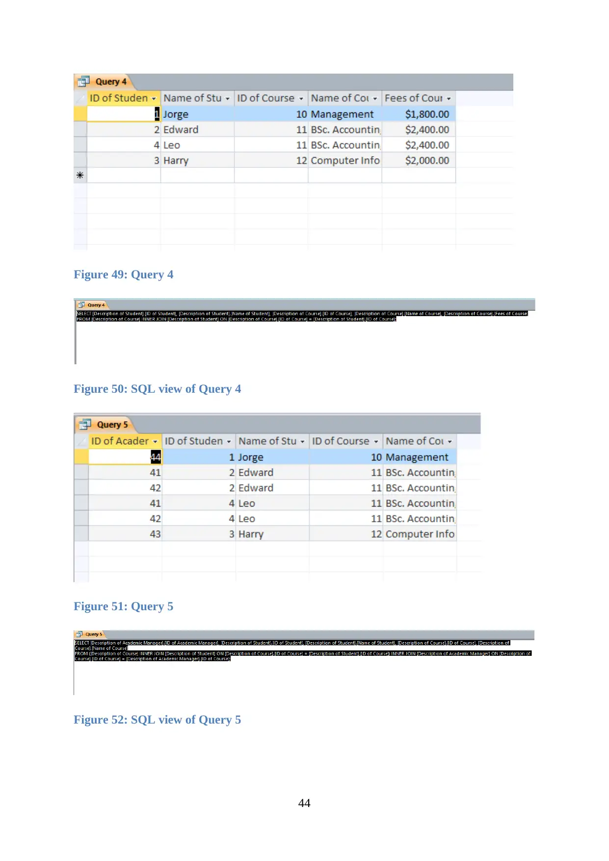
Figure 49: Query 4
Figure 50: SQL view of Query 4
Figure 51: Query 5
Figure 52: SQL view of Query 5
44
Figure 50: SQL view of Query 4
Figure 51: Query 5
Figure 52: SQL view of Query 5
44

Figure 53: Query 6
Figure 54: SQL view of Query 6
Figure 55: Query 7
Figure 56: SQL view of Query 7
45
Figure 54: SQL view of Query 6
Figure 55: Query 7
Figure 56: SQL view of Query 7
45
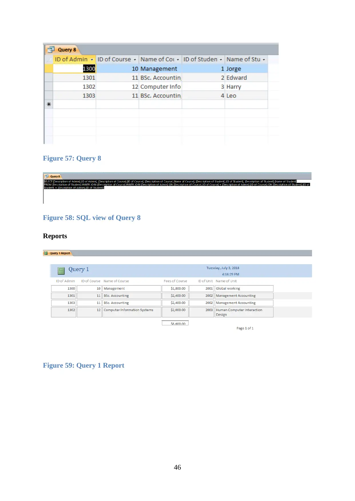
Figure 57: Query 8
Figure 58: SQL view of Query 8
Reports
Figure 59: Query 1 Report
46
Figure 58: SQL view of Query 8
Reports
Figure 59: Query 1 Report
46
Secure Best Marks with AI Grader
Need help grading? Try our AI Grader for instant feedback on your assignments.
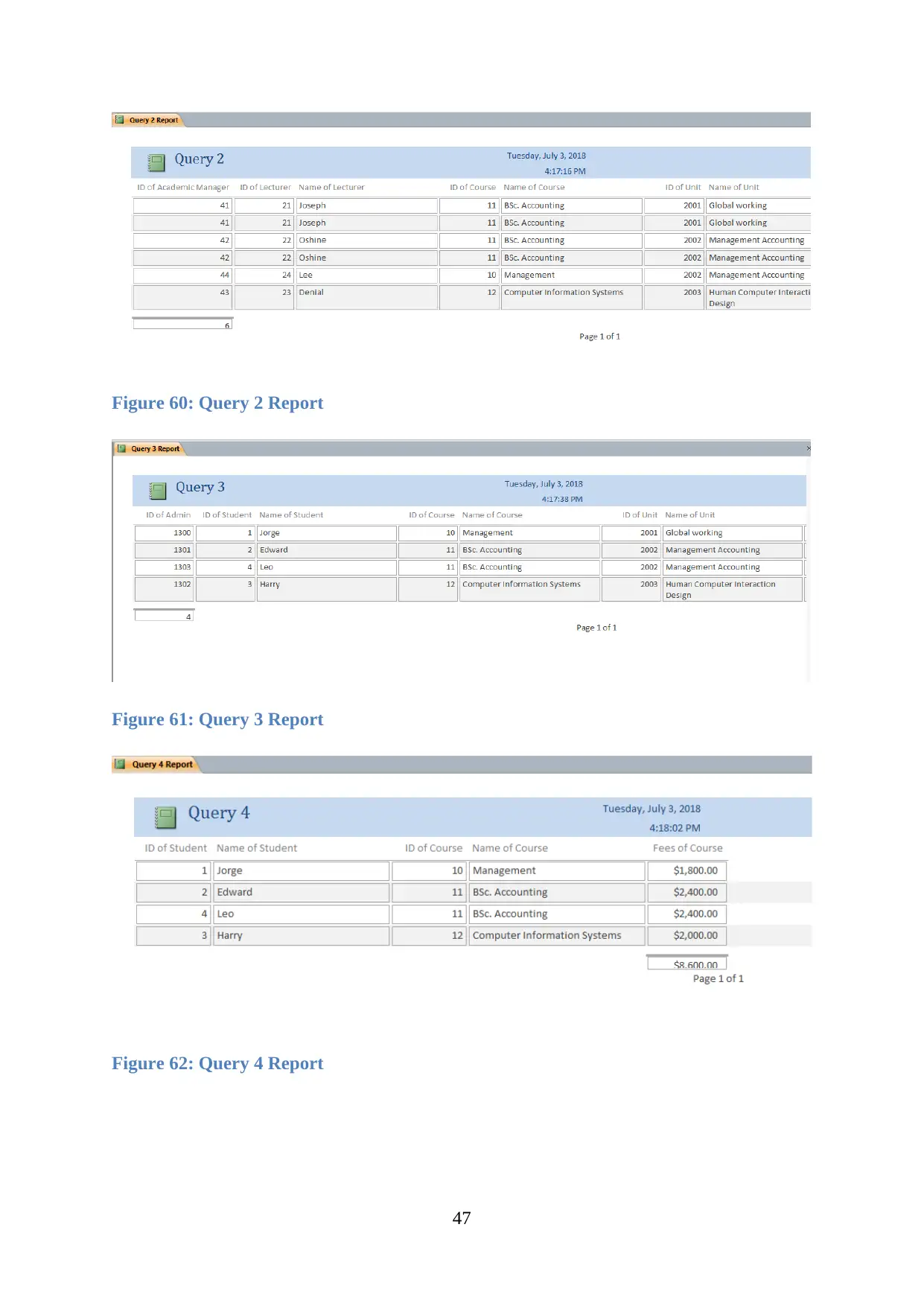
Figure 60: Query 2 Report
Figure 61: Query 3 Report
Figure 62: Query 4 Report
47
Figure 61: Query 3 Report
Figure 62: Query 4 Report
47
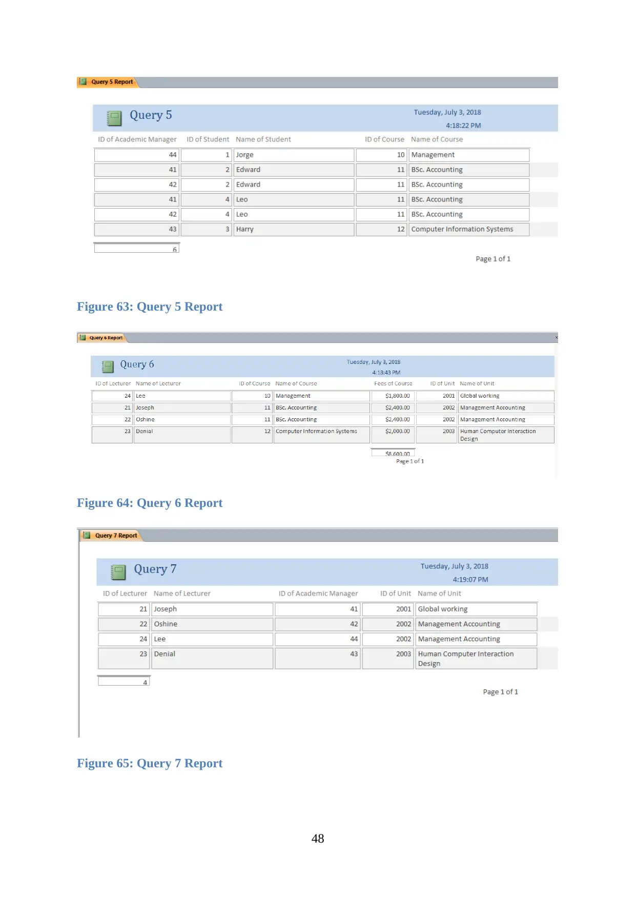
Figure 63: Query 5 Report
Figure 64: Query 6 Report
Figure 65: Query 7 Report
48
Figure 64: Query 6 Report
Figure 65: Query 7 Report
48
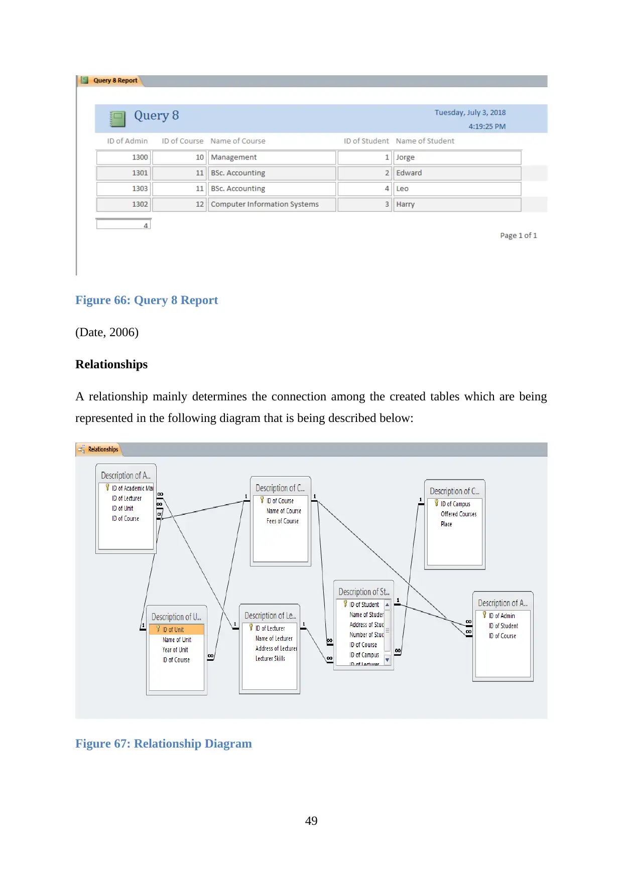
Figure 66: Query 8 Report
(Date, 2006)
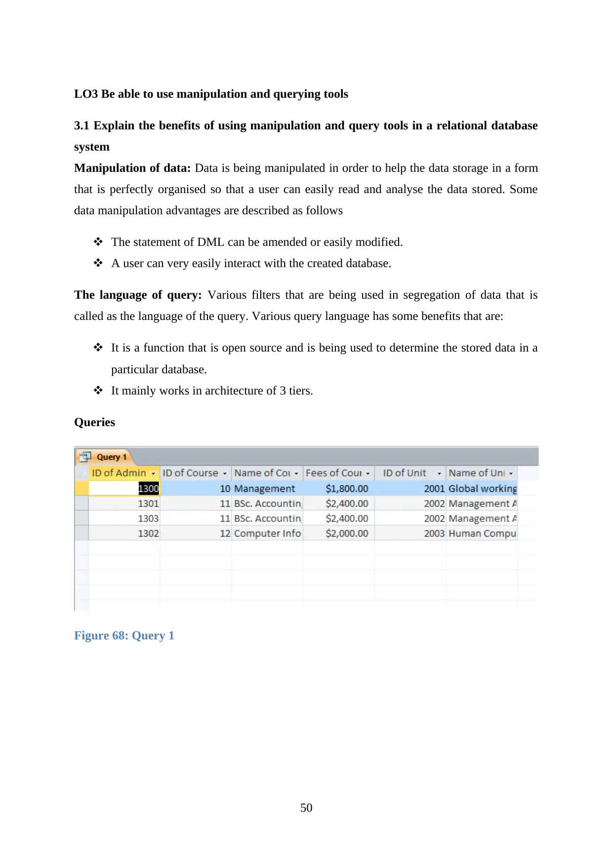
Relationships
A relationship mainly determines the connection among the created tables which are being
represented in the following diagram that is being described below:
Figure 67: Relationship Diagram
49
(Date, 2006)
Relationships
A relationship mainly determines the connection among the created tables which are being
represented in the following diagram that is being described below:
Figure 67: Relationship Diagram
49
Paraphrase This Document
Need a fresh take? Get an instant paraphrase of this document with our AI Paraphraser
LO3 Be able to use manipulation and querying tools
3.1 Explain the benefits of using manipulation and query tools in a relational database
system
Manipulation of data: Data is being manipulated in order to help the data storage in a form
that is perfectly organised so that a user can easily read and analyse the data stored. Some
data manipulation advantages are described as follows
The statement of DML can be amended or easily modified.
A user can very easily interact with the created database.
The language of query: Various filters that are being used in segregation of data that is
called as the language of the query. Various query language has some benefits that are:
It is a function that is open source and is being used to determine the stored data in a
particular database.
It mainly works in architecture of 3 tiers.
Queries
Figure 68: Query 1
50
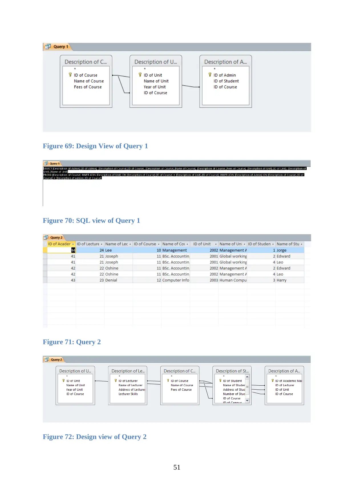
Figure 69: Design View of Query 1
Figure 70: SQL view of Query 1
Figure 71: Query 2
Figure 72: Design view of Query 2
51
Figure 70: SQL view of Query 1
Figure 71: Query 2
Figure 72: Design view of Query 2
51
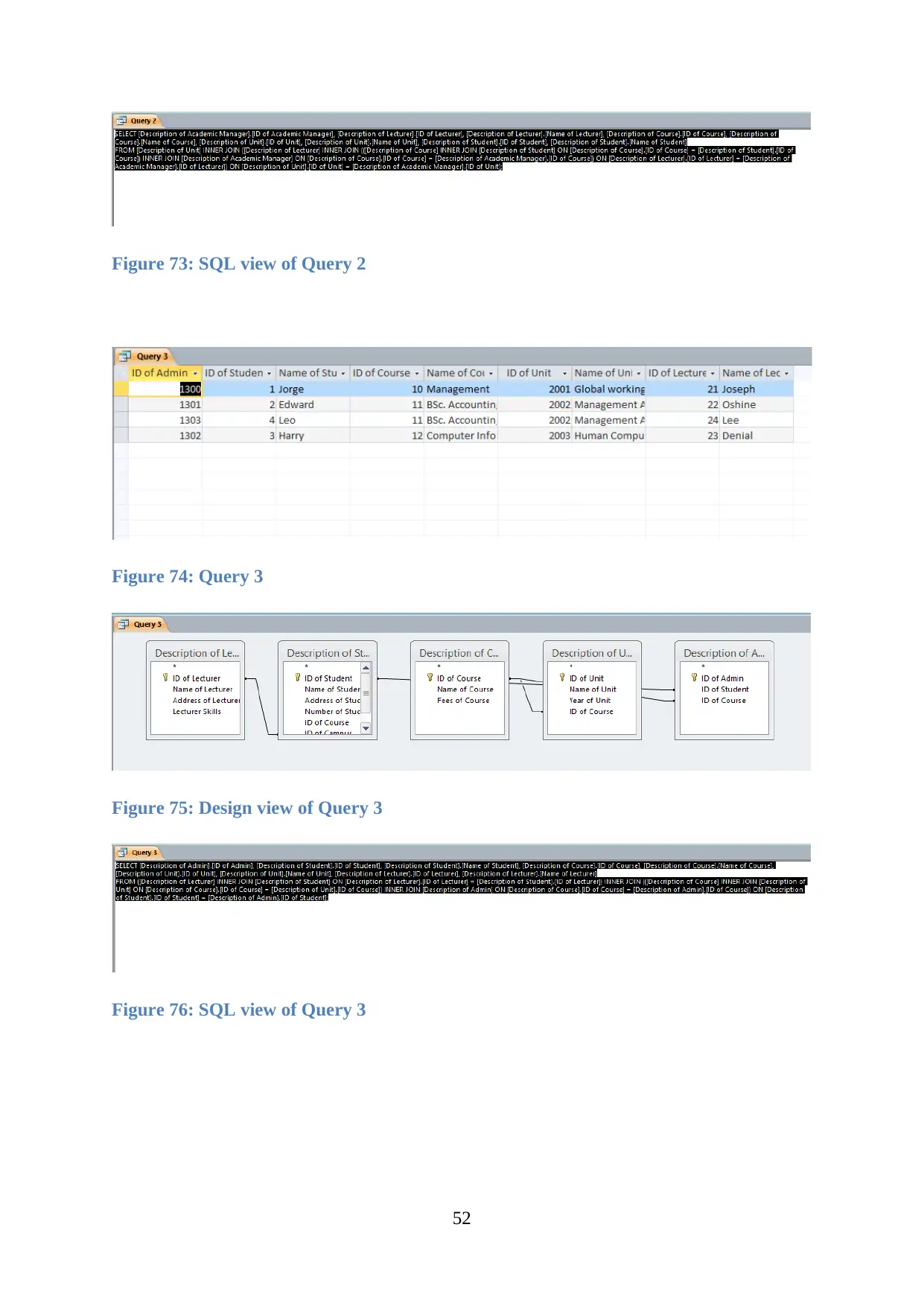
Figure 73: SQL view of Query 2
Figure 74: Query 3
Figure 75: Design view of Query 3
Figure 76: SQL view of Query 3
52
Figure 74: Query 3
Figure 75: Design view of Query 3
Figure 76: SQL view of Query 3
52
Secure Best Marks with AI Grader
Need help grading? Try our AI Grader for instant feedback on your assignments.
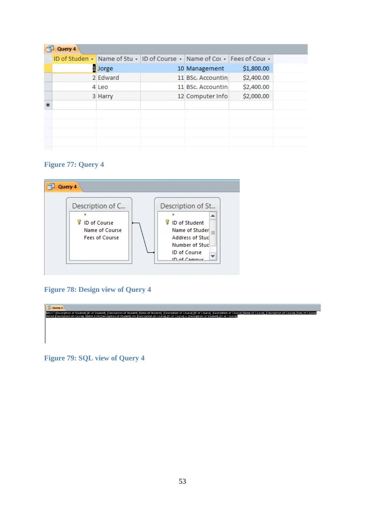
Figure 77: Query 4
Figure 78: Design view of Query 4
Figure 79: SQL view of Query 4
53
Figure 78: Design view of Query 4
Figure 79: SQL view of Query 4
53
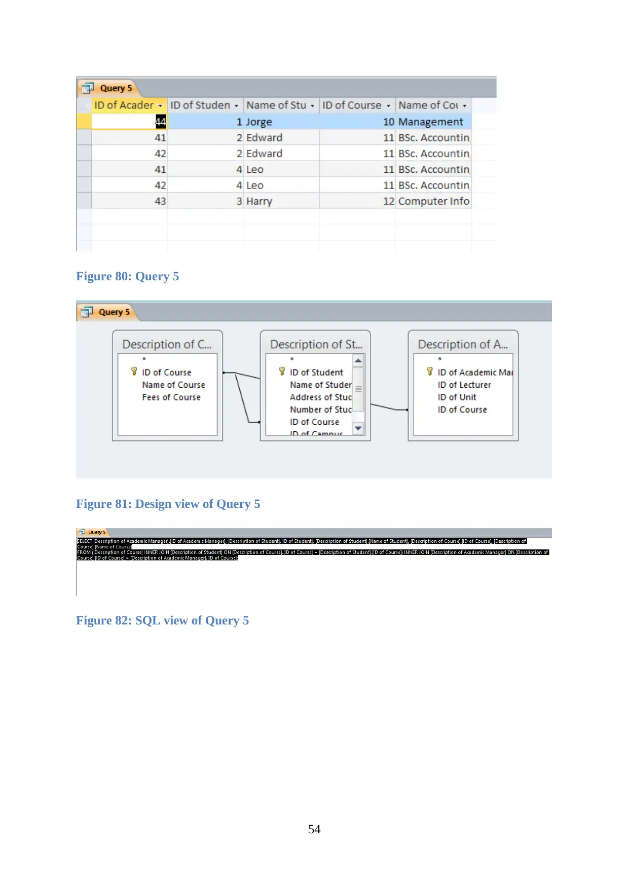
Figure 80: Query 5
Figure 81: Design view of Query 5
Figure 82: SQL view of Query 5
54
Figure 81: Design view of Query 5
Figure 82: SQL view of Query 5
54
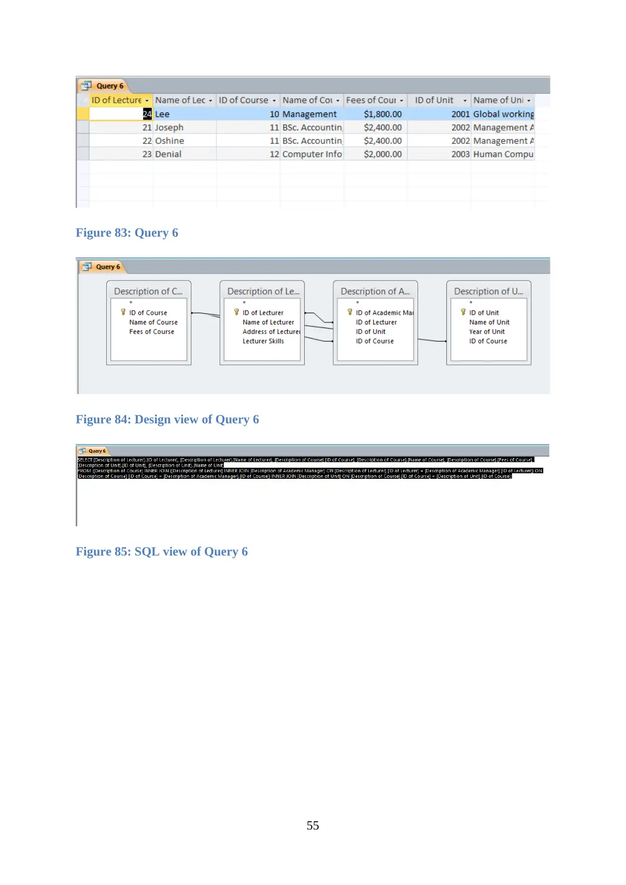
Figure 83: Query 6
Figure 84: Design view of Query 6
Figure 85: SQL view of Query 6
55
Figure 84: Design view of Query 6
Figure 85: SQL view of Query 6
55
Paraphrase This Document
Need a fresh take? Get an instant paraphrase of this document with our AI Paraphraser

Figure 86: Query 7
Figure 87: Design view of Query 7
Figure 88: SQL view of Query 7
56
Figure 87: Design view of Query 7
Figure 88: SQL view of Query 7
56
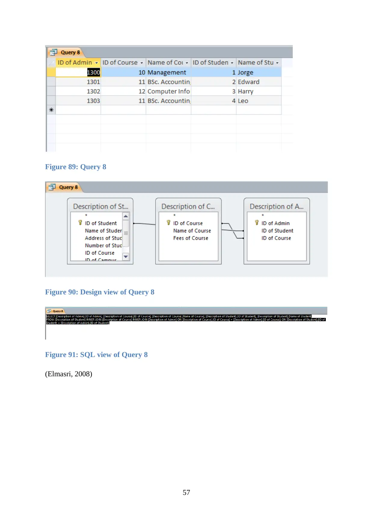
Figure 89: Query 8
Figure 90: Design view of Query 8
Figure 91: SQL view of Query 8
(Elmasri, 2008)
57
Figure 90: Design view of Query 8
Figure 91: SQL view of Query 8
(Elmasri, 2008)
57
3.2 Implement a query language into the relational database system
Several data is being extracted from a tool of the query and different functions are later
performed using the query language help. Few queries are being used for data extraction from
the records of Dominican college which is being described as:
Query 1
A query is generated after adding Description, of Course, Description of student and
Description of Units along with its attributes.
Figure 92: Query 1
Figure 93: Design View of Query 1
Figure 94: SQL view of Query 1
58
Secure Best Marks with AI Grader
Need help grading? Try our AI Grader for instant feedback on your assignments.

Figure 95: Query 1 Report
Query 2
A query is generated after adding Description of Course and Description of Units along with
its attributes.
Figure 96: Query 2
Figure 97: Design view of Query 2
59
Query 2
A query is generated after adding Description of Course and Description of Units along with
its attributes.
Figure 96: Query 2
Figure 97: Design view of Query 2
59
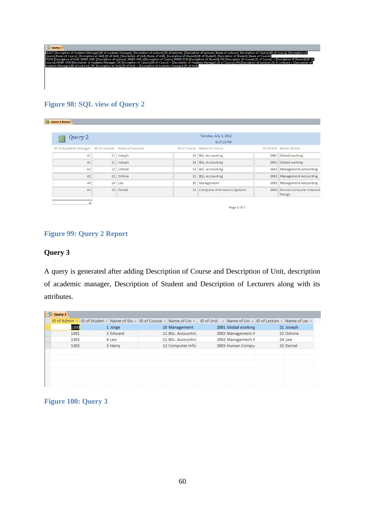
Figure 98: SQL view of Query 2
Figure 99: Query 2 Report
Query 3
A query is generated after adding Description of Course and Description of Unit, description
of academic manager, Description of Student and Description of Lecturers along with its
attributes.
Figure 100: Query 3
60
Figure 99: Query 2 Report
Query 3
A query is generated after adding Description of Course and Description of Unit, description
of academic manager, Description of Student and Description of Lecturers along with its
attributes.
Figure 100: Query 3
60
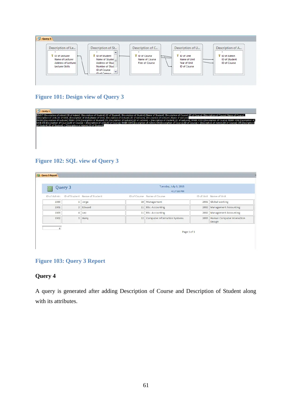
Figure 101: Design view of Query 3
Figure 102: SQL view of Query 3
Figure 103: Query 3 Report
Query 4
A query is generated after adding Description of Course and Description of Student along
with its attributes.
61
Figure 102: SQL view of Query 3
Figure 103: Query 3 Report
Query 4
A query is generated after adding Description of Course and Description of Student along
with its attributes.
61
Paraphrase This Document
Need a fresh take? Get an instant paraphrase of this document with our AI Paraphraser

Figure 104: Query 4
Figure 105: Design view of Query 4
Figure 106: SQL view of Query 4
62
Figure 105: Design view of Query 4
Figure 106: SQL view of Query 4
62
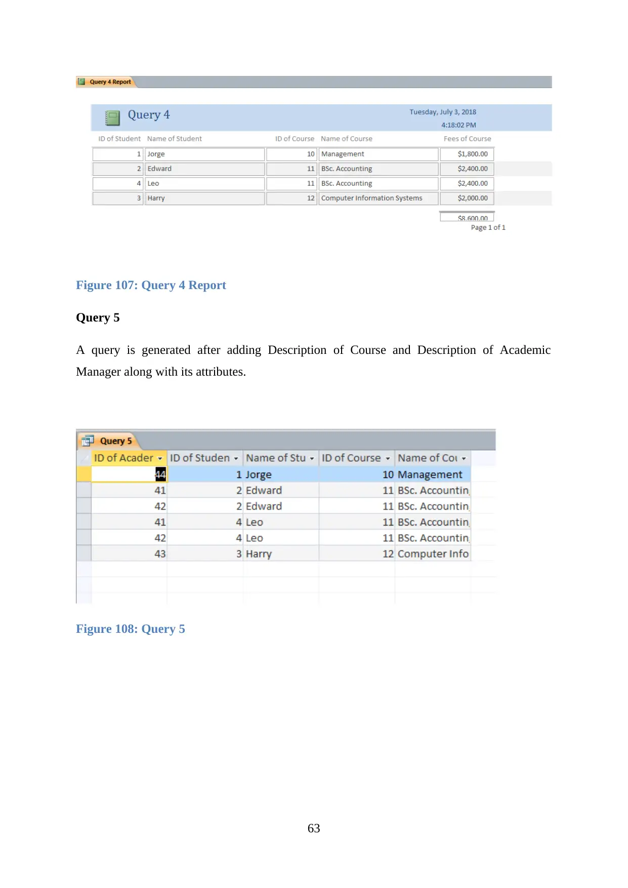
Figure 107: Query 4 Report
Query 5
A query is generated after adding Description of Course and Description of Academic
Manager along with its attributes.
Figure 108: Query 5
63
Query 5
A query is generated after adding Description of Course and Description of Academic
Manager along with its attributes.
Figure 108: Query 5
63

Figure 109: Design view of Query 5
Figure 110: SQL view of Query 5
Figure 111: Query 5 Report
Query 6
A query is generated after adding Description of Course and Description of Lecturer,
Description of admin, Description of the unit, Description of students along with its
attributes.
64
Figure 110: SQL view of Query 5
Figure 111: Query 5 Report
Query 6
A query is generated after adding Description of Course and Description of Lecturer,
Description of admin, Description of the unit, Description of students along with its
attributes.
64
Secure Best Marks with AI Grader
Need help grading? Try our AI Grader for instant feedback on your assignments.
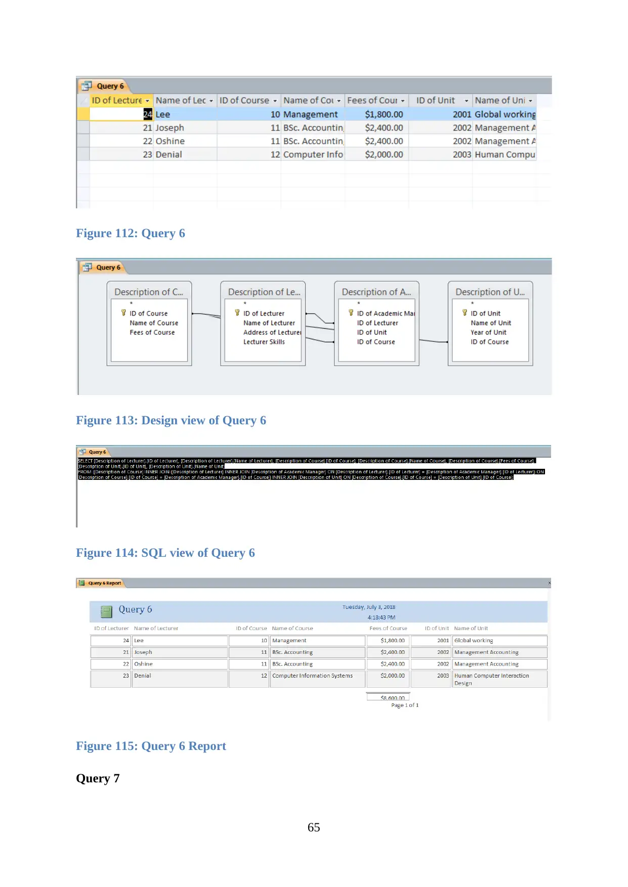
Figure 112: Query 6
Figure 113: Design view of Query 6
Figure 114: SQL view of Query 6
Figure 115: Query 6 Report
Query 7
65
Figure 113: Design view of Query 6
Figure 114: SQL view of Query 6
Figure 115: Query 6 Report
Query 7
65

A query is generated after adding Description, of Course, Description of admin and
Description of the unit along with its attributes.
Figure 116: Query 7
Figure 117: Design view of Query 7
Figure 118: SQL view of Query 7
66
Description of the unit along with its attributes.
Figure 116: Query 7
Figure 117: Design view of Query 7
Figure 118: SQL view of Query 7
66

Figure 119: Query 7 Report
Query 8
A query is generated after adding Description of the unit, Description of Lecturer,
Description of Academic Manager along with its attributes.
Figure 120: Query 8
67
Query 8
A query is generated after adding Description of the unit, Description of Lecturer,
Description of Academic Manager along with its attributes.
Figure 120: Query 8
67
Paraphrase This Document
Need a fresh take? Get an instant paraphrase of this document with our AI Paraphraser

Figure 121: Design view of Query 8
Figure 122: SQL view of Query 8
Figure 123: Query 8 Report
68
Figure 122: SQL view of Query 8
Figure 123: Query 8 Report
68
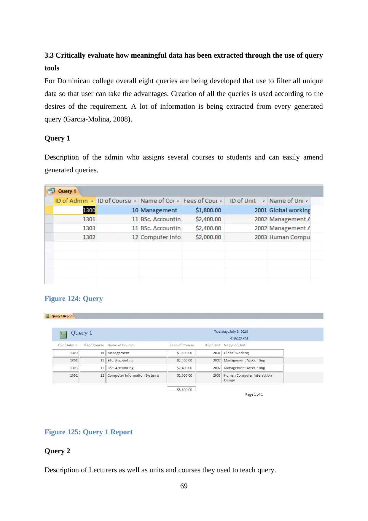
3.3 Critically evaluate how meaningful data has been extracted through the use of query
tools
For Dominican college overall eight queries are being developed that use to filter all unique
data so that user can take the advantages. Creation of all the queries is used according to the
desires of the requirement. A lot of information is being extracted from every generated
query (Garcia-Molina, 2008).
Query 1
Description of the admin who assigns several courses to students and can easily amend
generated queries.
Figure 124: Query
Figure 125: Query 1 Report
Query 2
Description of Lecturers as well as units and courses they used to teach query.
69
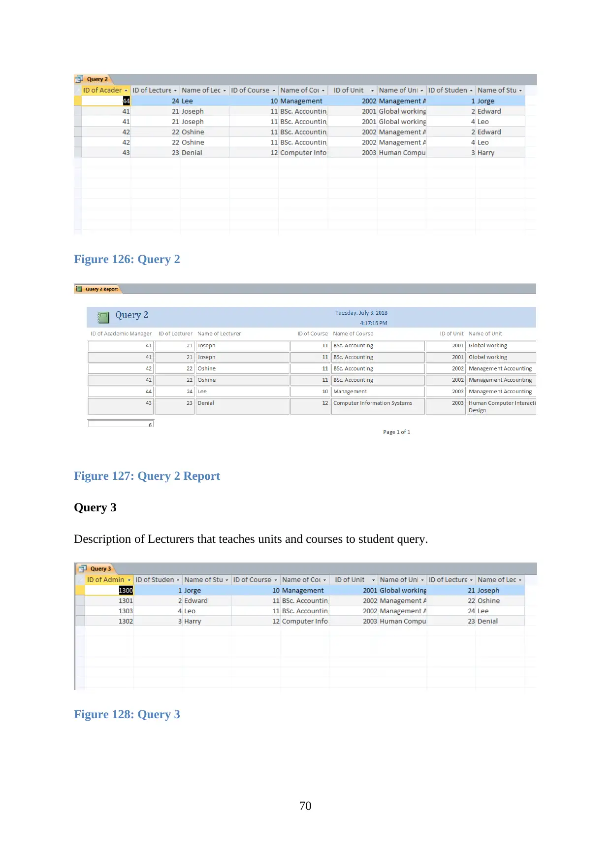
Figure 126: Query 2
Figure 127: Query 2 Report
Query 3
Description of Lecturers that teaches units and courses to student query.
Figure 128: Query 3
70
Figure 127: Query 2 Report
Query 3
Description of Lecturers that teaches units and courses to student query.
Figure 128: Query 3
70
Secure Best Marks with AI Grader
Need help grading? Try our AI Grader for instant feedback on your assignments.
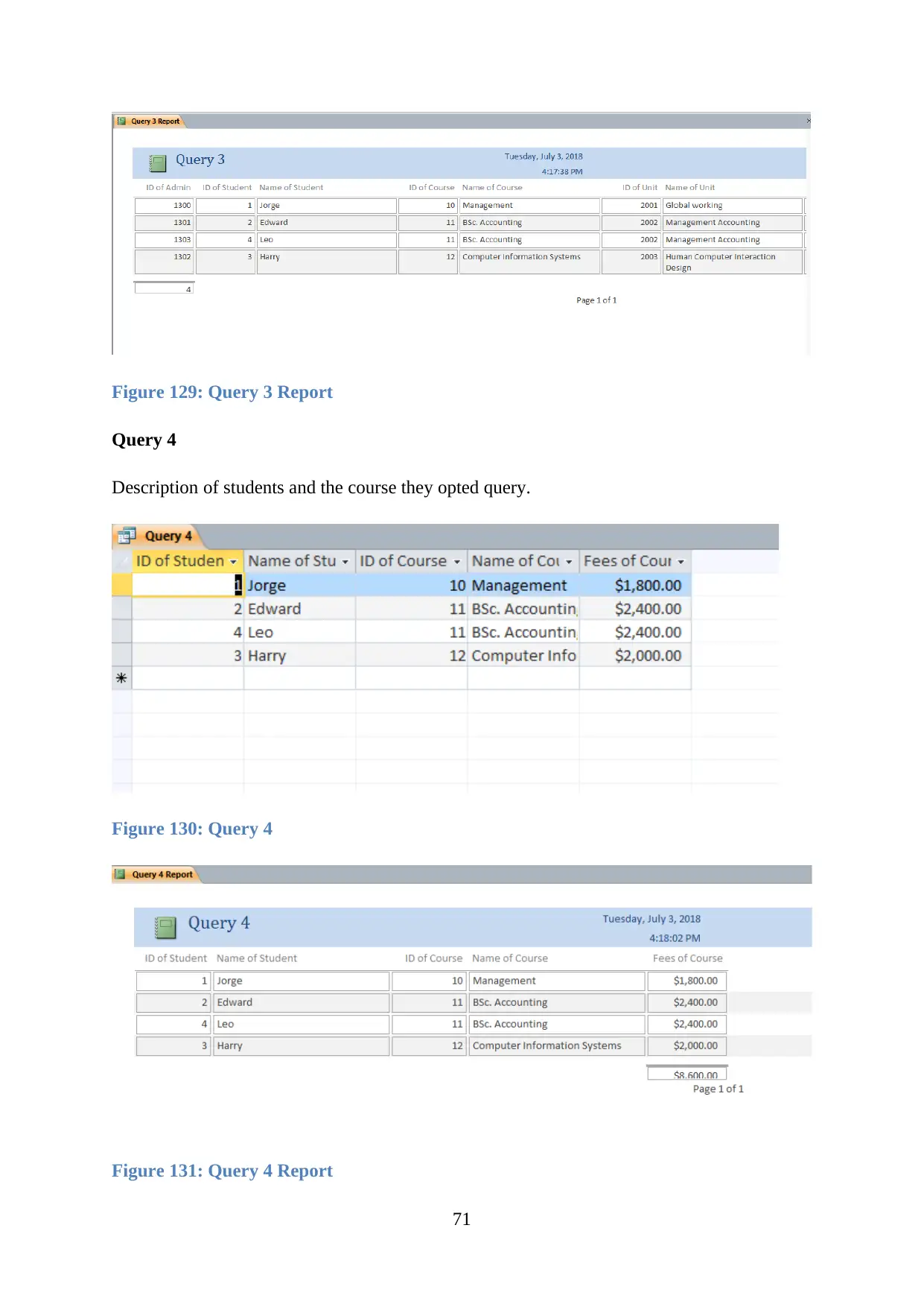
Figure 129: Query 3 Report
Query 4
Description of students and the course they opted query.
Figure 130: Query 4
Figure 131: Query 4 Report
71
Query 4
Description of students and the course they opted query.
Figure 130: Query 4
Figure 131: Query 4 Report
71
Query 5
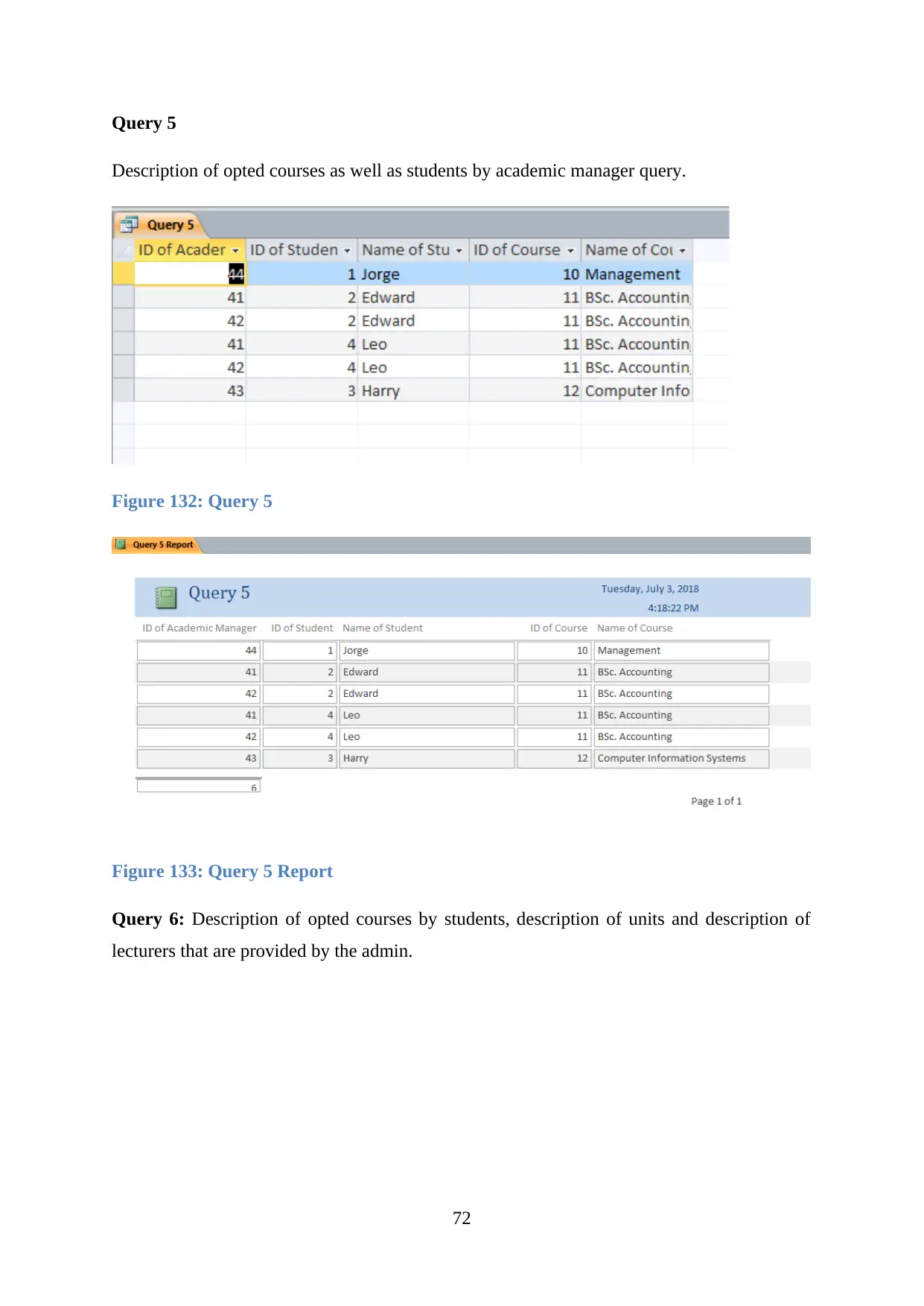
Description of opted courses as well as students by academic manager query.
Figure 132: Query 5
Figure 133: Query 5 Report
Query 6: Description of opted courses by students, description of units and description of
lecturers that are provided by the admin.
72
Description of opted courses as well as students by academic manager query.
Figure 132: Query 5
Figure 133: Query 5 Report
Query 6: Description of opted courses by students, description of units and description of
lecturers that are provided by the admin.
72
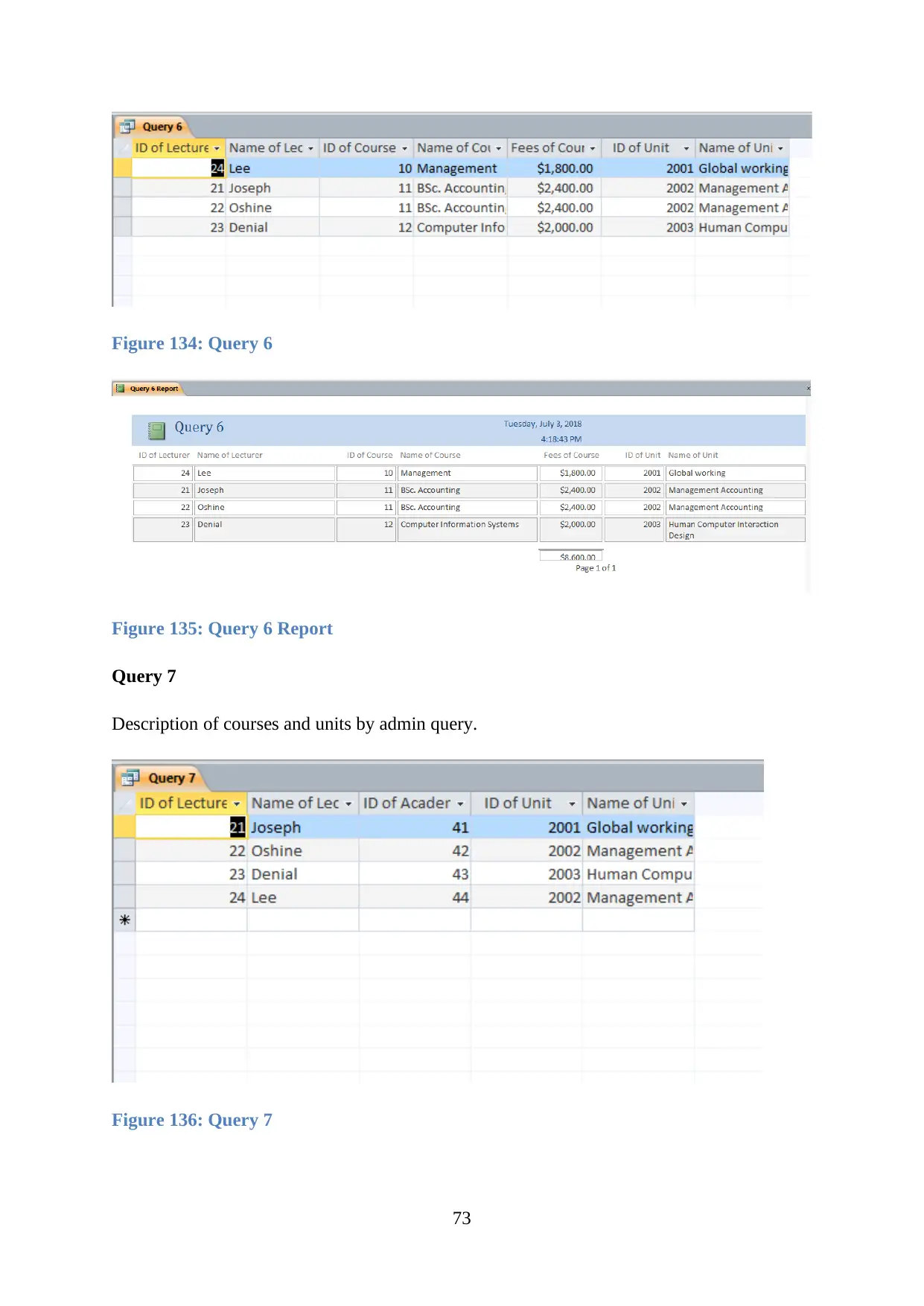
Figure 134: Query 6
Figure 135: Query 6 Report
Query 7
Description of courses and units by admin query.
Figure 136: Query 7
73
Figure 135: Query 6 Report
Query 7
Description of courses and units by admin query.
Figure 136: Query 7
73
Paraphrase This Document
Need a fresh take? Get an instant paraphrase of this document with our AI Paraphraser

Figure 137: Query 7 Report
Query 8
Academic manager can amend all description of lecturers and unit query.
Figure 138: Query 8
74
Query 8
Academic manager can amend all description of lecturers and unit query.
Figure 138: Query 8
74
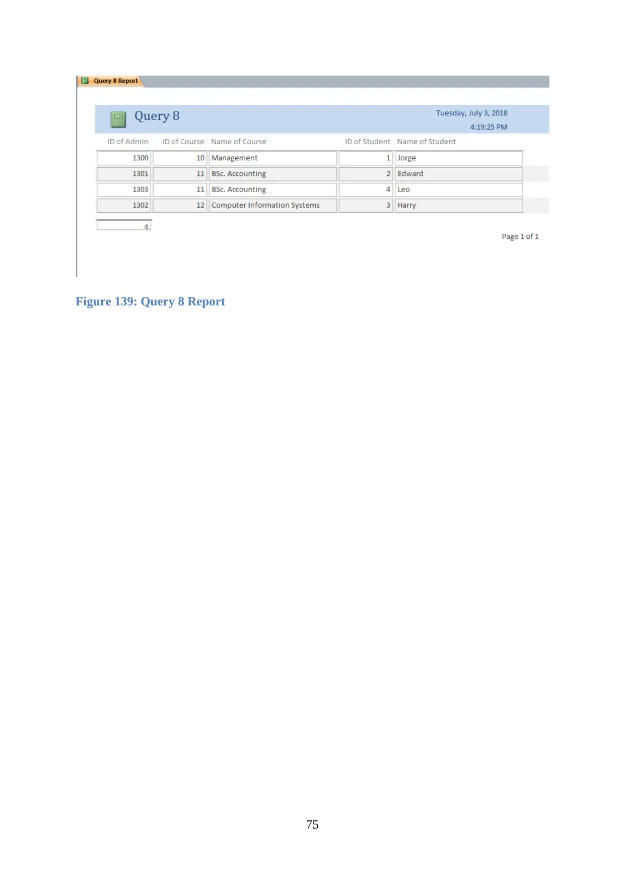
Figure 139: Query 8 Report
75
75
LO4 Be able to test and document relational database systems
4.1 Critically review and test a relational database system
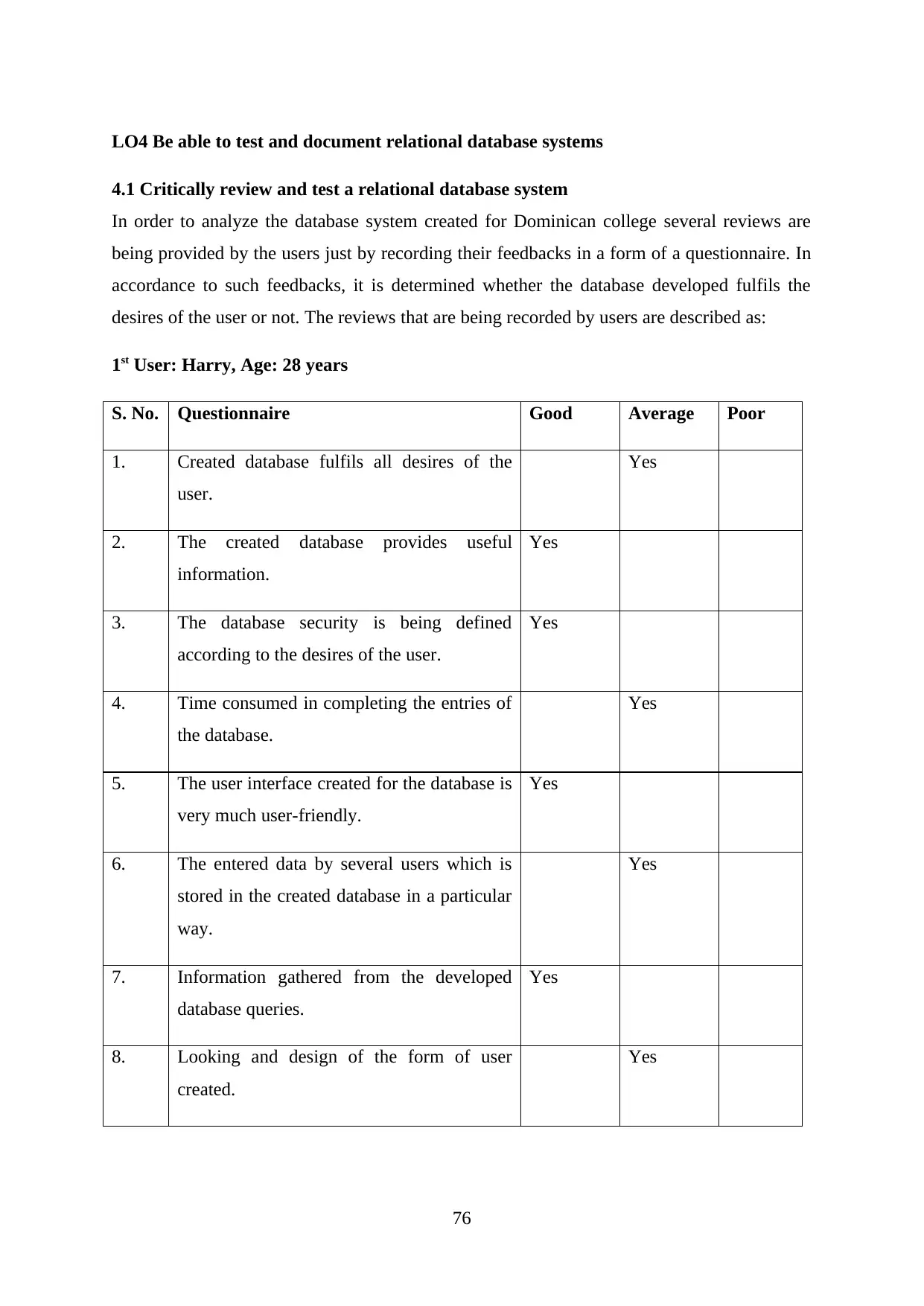
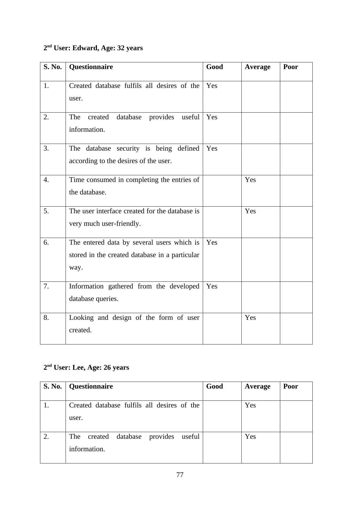
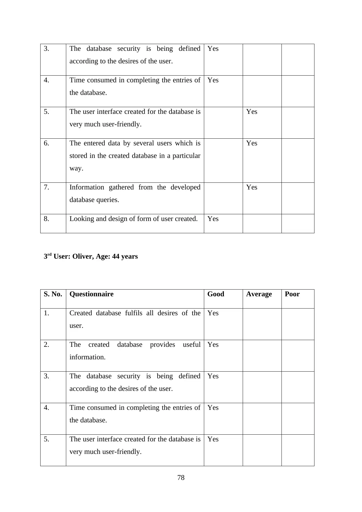
In order to analyze the database system created for Dominican college several reviews are
being provided by the users just by recording their feedbacks in a form of a questionnaire. In
accordance to such feedbacks, it is determined whether the database developed fulfils the
desires of the user or not. The reviews that are being recorded by users are described as:
1st User: Harry, Age: 28 years
S. No. Questionnaire Good Average Poor
1. Created database fulfils all desires of the
user.
Yes
2. The created database provides useful
information.
Yes
3. The database security is being defined
according to the desires of the user.
Yes
4. Time consumed in completing the entries of
the database.
Yes
5. The user interface created for the database is
very much user-friendly.
Yes
6. The entered data by several users which is
stored in the created database in a particular
way.
Yes
7. Information gathered from the developed
database queries.
Yes
8. Looking and design of the form of user
created.
Yes
76
Secure Best Marks with AI Grader
Need help grading? Try our AI Grader for instant feedback on your assignments.
2nd User: Edward, Age: 32 years
S. No. Questionnaire Good Average Poor
1. Created database fulfils all desires of the
user.
Yes
2. The created database provides useful
information.
Yes
3. The database security is being defined
according to the desires of the user.
Yes
4. Time consumed in completing the entries of
the database.
Yes
5. The user interface created for the database is
very much user-friendly.
Yes
6. The entered data by several users which is
stored in the created database in a particular
way.
Yes
7. Information gathered from the developed
database queries.
Yes
8. Looking and design of the form of user
created.
Yes
2nd User: Lee, Age: 26 years
S. No. Questionnaire Good Average Poor
1. Created database fulfils all desires of the
user.
Yes
2. The created database provides useful
information.
Yes
77
S. No. Questionnaire Good Average Poor
1. Created database fulfils all desires of the
user.
Yes
2. The created database provides useful
information.
Yes
3. The database security is being defined
according to the desires of the user.
Yes
4. Time consumed in completing the entries of
the database.
Yes
5. The user interface created for the database is
very much user-friendly.
Yes
6. The entered data by several users which is
stored in the created database in a particular
way.
Yes
7. Information gathered from the developed
database queries.
Yes
8. Looking and design of the form of user
created.
Yes
2nd User: Lee, Age: 26 years
S. No. Questionnaire Good Average Poor
1. Created database fulfils all desires of the
user.
Yes
2. The created database provides useful
information.
Yes
77
3. The database security is being defined
according to the desires of the user.
Yes
4. Time consumed in completing the entries of
the database.
Yes
5. The user interface created for the database is
very much user-friendly.
Yes
6. The entered data by several users which is
stored in the created database in a particular
way.
Yes
7. Information gathered from the developed
database queries.
Yes
8. Looking and design of form of user created. Yes
3rd User: Oliver, Age: 44 years
S. No. Questionnaire Good Average Poor
1. Created database fulfils all desires of the
user.
Yes
2. The created database provides useful
information.
Yes
3. The database security is being defined
according to the desires of the user.
Yes
4. Time consumed in completing the entries of
the database.
Yes
5. The user interface created for the database is
very much user-friendly.
Yes
78
according to the desires of the user.
Yes
4. Time consumed in completing the entries of
the database.
Yes
5. The user interface created for the database is
very much user-friendly.
Yes
6. The entered data by several users which is
stored in the created database in a particular
way.
Yes
7. Information gathered from the developed
database queries.
Yes
8. Looking and design of form of user created. Yes
3rd User: Oliver, Age: 44 years
S. No. Questionnaire Good Average Poor
1. Created database fulfils all desires of the
user.
Yes
2. The created database provides useful
information.
Yes
3. The database security is being defined
according to the desires of the user.
Yes
4. Time consumed in completing the entries of
the database.
Yes
5. The user interface created for the database is
very much user-friendly.
Yes
78

6. The entered data by several users which is
stored in the created database in a particular
way.
Yes
7. Information gathered from the developed
database queries.
Yes
8. Looking and design of the form of user
created.
Yes
4th User: Daniel, Age: 33 years
S. No. Questionnaire Good Average Poor
1. Created database fulfils all desires of the
user.
Yes
2. The created database provides useful
information.
Yes
3. The database security is being defined
according to the desires of the user.
Yes
4. Time consumed in completing the entries of
the database.
Yes
5. The user interface created for the database is
very much user-friendly.
Yes
6. The entered data by several users which is
stored in the created database in a particular
way.
Yes
7. Information gathered from the developed
database queries.
Yes
8. Looking and design of the form of user
created.
Yes
79
stored in the created database in a particular
way.
Yes
7. Information gathered from the developed
database queries.
Yes
8. Looking and design of the form of user
created.
Yes
4th User: Daniel, Age: 33 years
S. No. Questionnaire Good Average Poor
1. Created database fulfils all desires of the
user.
Yes
2. The created database provides useful
information.
Yes
3. The database security is being defined
according to the desires of the user.
Yes
4. Time consumed in completing the entries of
the database.
Yes
5. The user interface created for the database is
very much user-friendly.
Yes
6. The entered data by several users which is
stored in the created database in a particular
way.
Yes
7. Information gathered from the developed
database queries.
Yes
8. Looking and design of the form of user
created.
Yes
79
Paraphrase This Document
Need a fresh take? Get an instant paraphrase of this document with our AI Paraphraser

(Abadi, Boncz, and Harizopoulos, 2009)
80
80
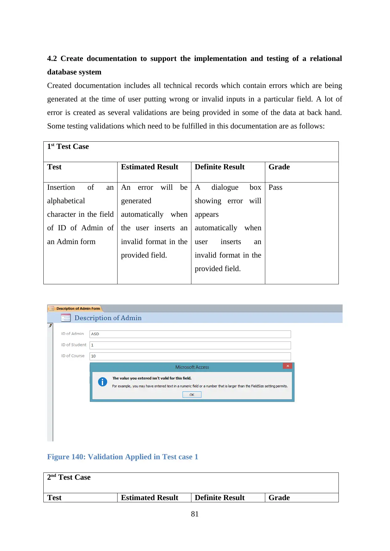
4.2 Create documentation to support the implementation and testing of a relational
database system
Created documentation includes all technical records which contain errors which are being
generated at the time of user putting wrong or invalid inputs in a particular field. A lot of
error is created as several validations are being provided in some of the data at back hand.
Some testing validations which need to be fulfilled in this documentation are as follows:
1st Test Case
Test Estimated Result Definite Result Grade
Insertion of an
alphabetical
character in the field
of ID of Admin of
an Admin form
An error will be
generated
automatically when
the user inserts an
invalid format in the
provided field.
A dialogue box
showing error will
appears
automatically when
user inserts an
invalid format in the
provided field.
Pass
Figure 140: Validation Applied in Test case 1
2nd Test Case
Test Estimated Result Definite Result Grade
81
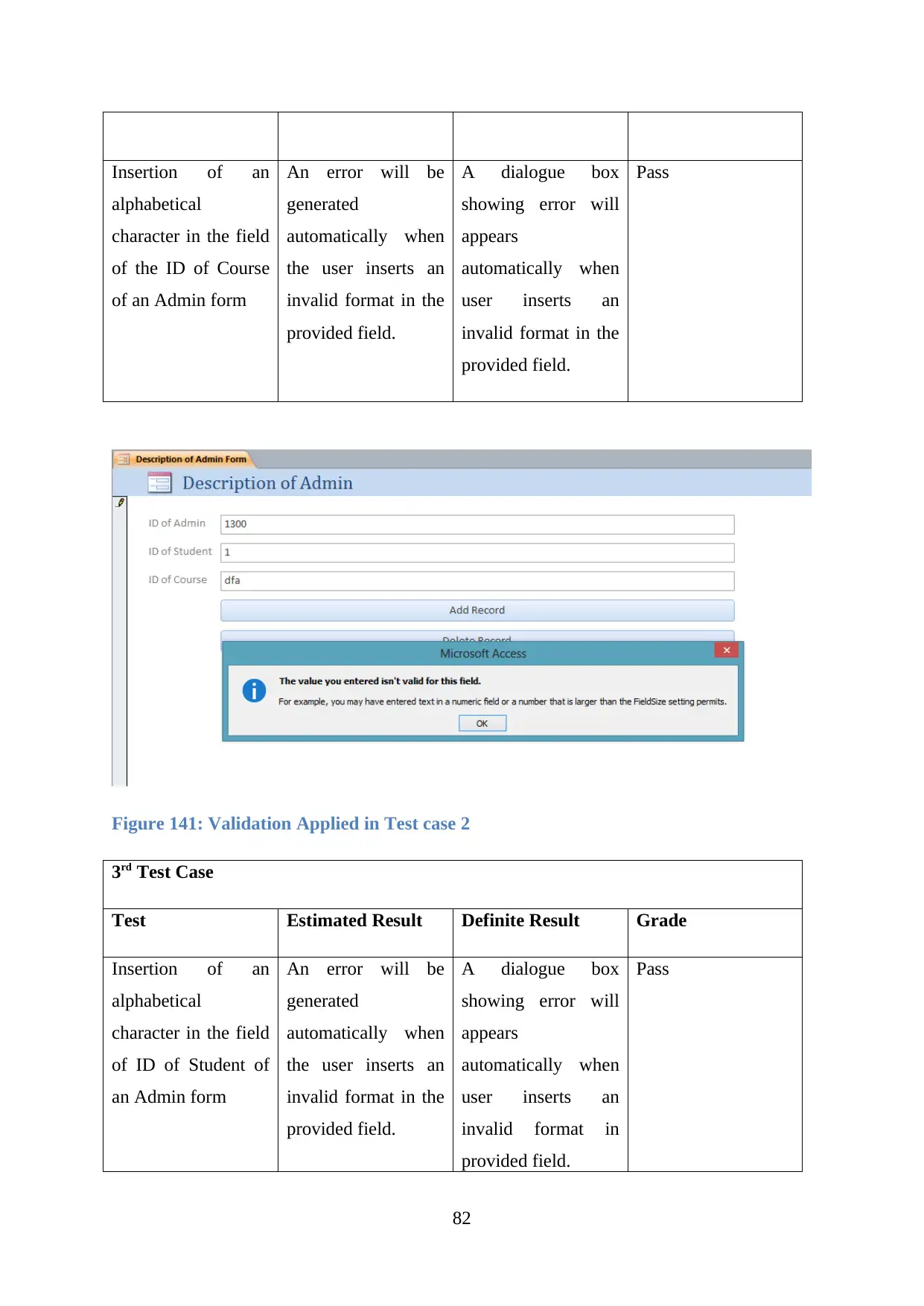
Insertion of an
alphabetical
character in the field
of the ID of Course
of an Admin form
An error will be
generated
automatically when
the user inserts an
invalid format in the
provided field.
A dialogue box
showing error will
appears
automatically when
user inserts an
invalid format in the
provided field.
Pass
Figure 141: Validation Applied in Test case 2
3rd Test Case
Test Estimated Result Definite Result Grade
Insertion of an
alphabetical
character in the field
of ID of Student of
an Admin form
An error will be
generated
automatically when
the user inserts an
invalid format in the
provided field.
A dialogue box
showing error will
appears
automatically when
user inserts an
invalid format in
provided field.
Pass
82
alphabetical
character in the field
of the ID of Course
of an Admin form
An error will be
generated
automatically when
the user inserts an
invalid format in the
provided field.
A dialogue box
showing error will
appears
automatically when
user inserts an
invalid format in the
provided field.
Pass
Figure 141: Validation Applied in Test case 2
3rd Test Case
Test Estimated Result Definite Result Grade
Insertion of an
alphabetical
character in the field
of ID of Student of
an Admin form
An error will be
generated
automatically when
the user inserts an
invalid format in the
provided field.
A dialogue box
showing error will
appears
automatically when
user inserts an
invalid format in
provided field.
Pass
82
Secure Best Marks with AI Grader
Need help grading? Try our AI Grader for instant feedback on your assignments.
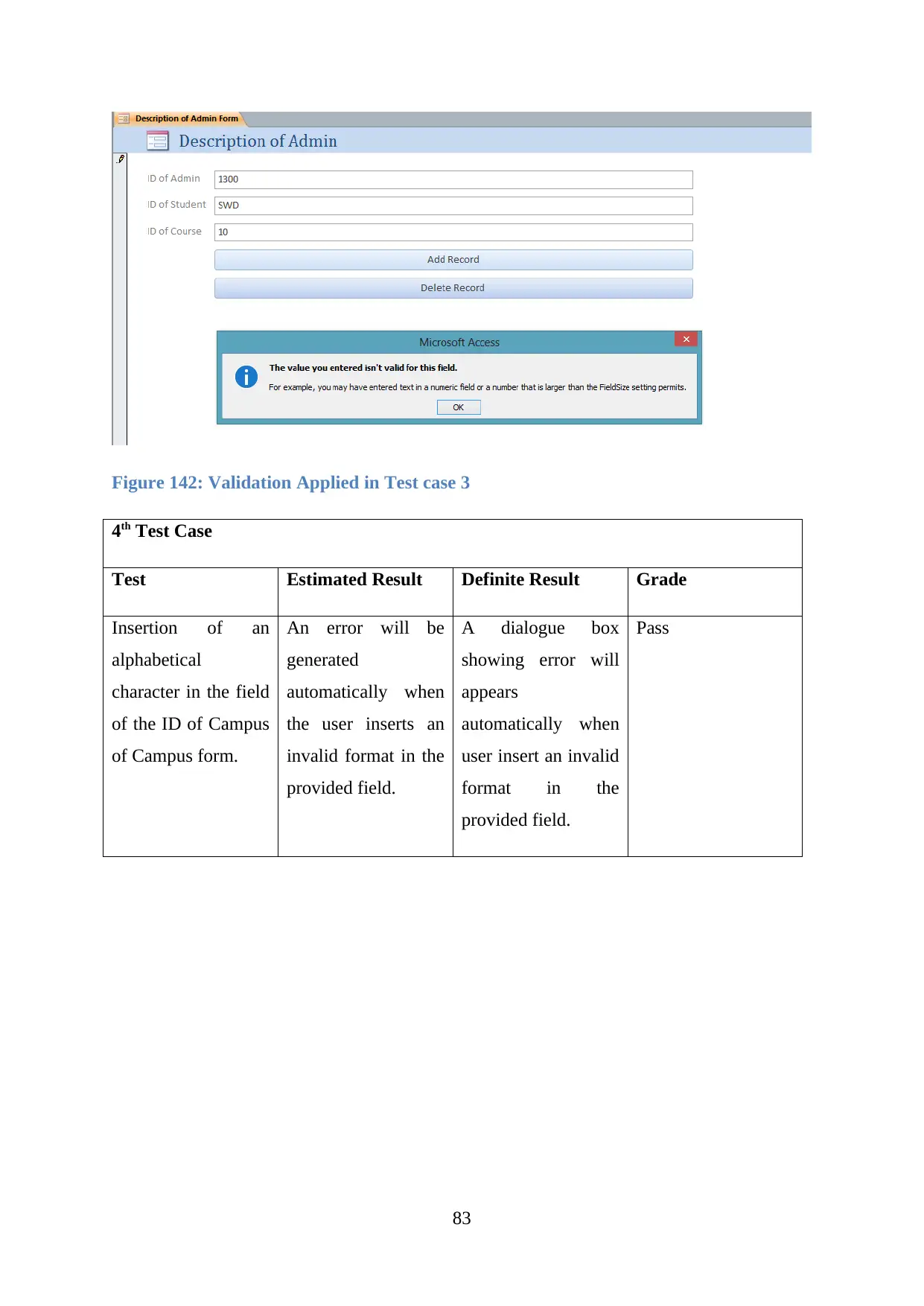
Figure 142: Validation Applied in Test case 3
4th Test Case
Test Estimated Result Definite Result Grade
Insertion of an
alphabetical
character in the field
of the ID of Campus
of Campus form.
An error will be
generated
automatically when
the user inserts an
invalid format in the
provided field.
A dialogue box
showing error will
appears
automatically when
user insert an invalid
format in the
provided field.
Pass
83

Figure 143: Validation Applied in Test case 4
5th Test Case
Test Estimated Result Definite Result Grade
Insertion of an
alphabetical
character in the field
of the ID of Course
of Course form.
An error will be
generated
automatically when
the user inserts an
invalid format in the
provided field.
A dialogue box
showing error will
appears
automatically when
user inserts an
invalid format in the
provided field.
Pass
84

Figure 144: Validation Applied in Test case 5
6th Test Case
Test Estimated Result Definite Result Grade
Insertion of an
alphabetical
character in the field
of Fees of Course of
Course form.
An error will be
generated
automatically when
the user inserts an
invalid format in the
provided field.
A dialogue box
showing error will
appears
automatically when
user inserts an
invalid format in the
provided field.
Pass
85
Paraphrase This Document
Need a fresh take? Get an instant paraphrase of this document with our AI Paraphraser
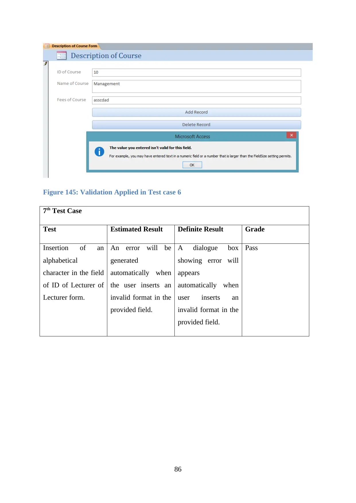
Figure 145: Validation Applied in Test case 6
7th Test Case
Test Estimated Result Definite Result Grade
Insertion of an
alphabetical
character in the field
of ID of Lecturer of
Lecturer form.
An error will be
generated
automatically when
the user inserts an
invalid format in the
provided field.
A dialogue box
showing error will
appears
automatically when
user inserts an
invalid format in the
provided field.
Pass
86
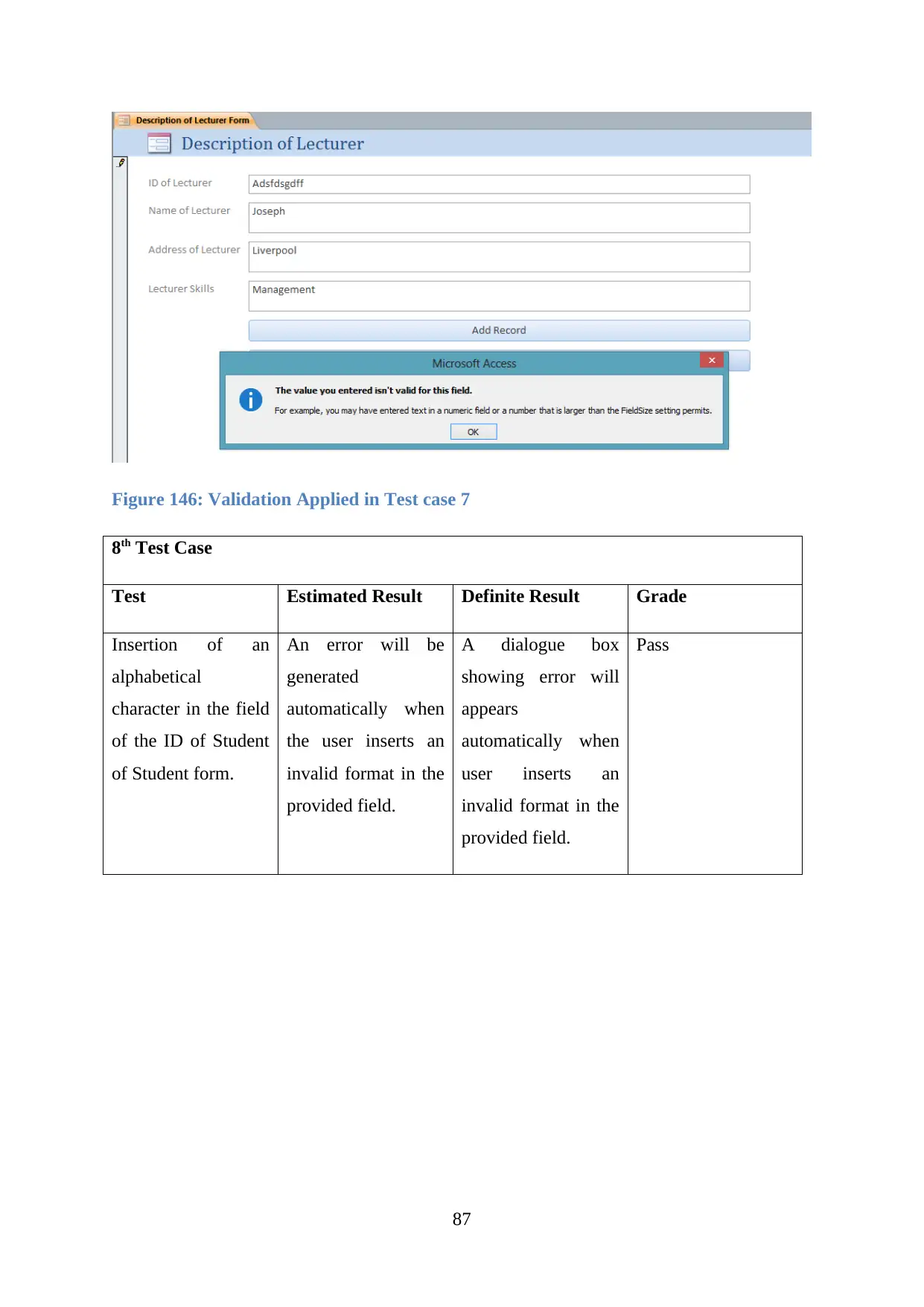
Figure 146: Validation Applied in Test case 7
8th Test Case
Test Estimated Result Definite Result Grade
Insertion of an
alphabetical
character in the field
of the ID of Student
of Student form.
An error will be
generated
automatically when
the user inserts an
invalid format in the
provided field.
A dialogue box
showing error will
appears
automatically when
user inserts an
invalid format in the
provided field.
Pass
87
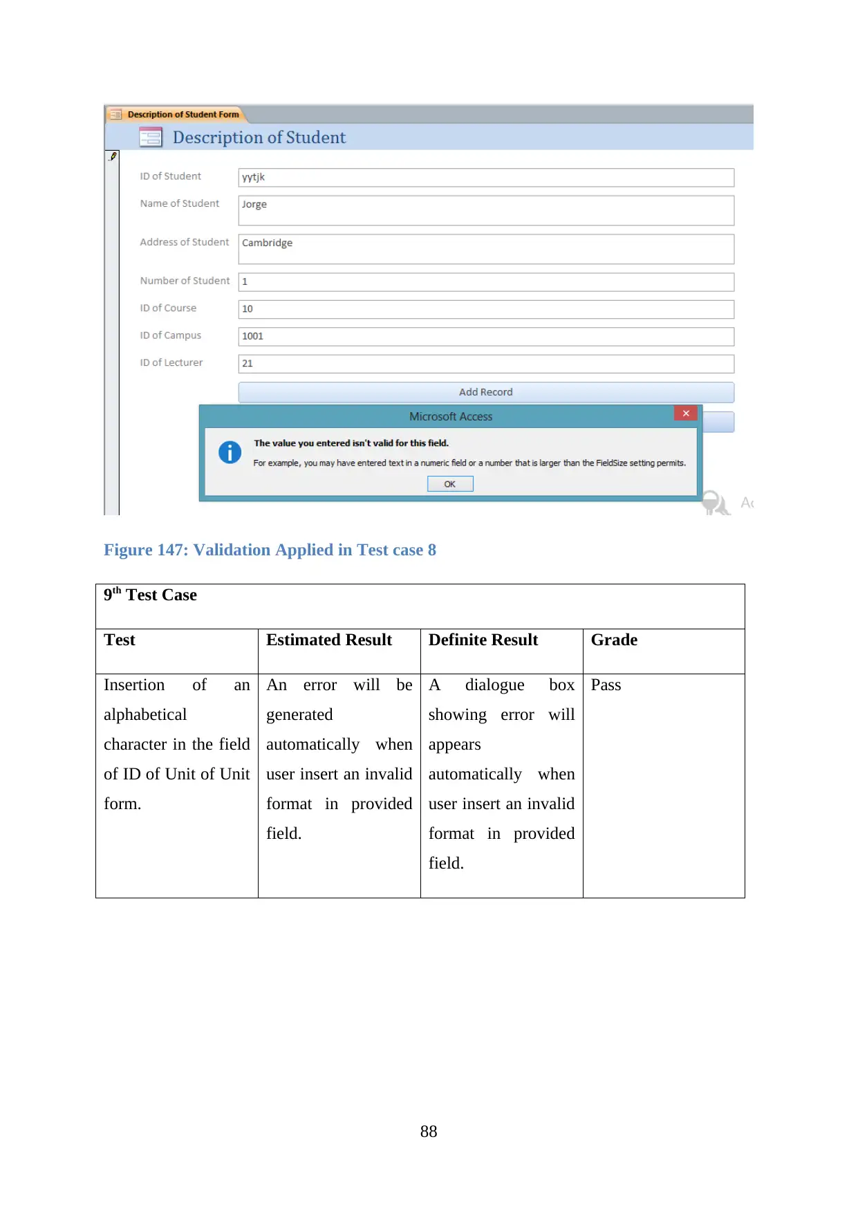
Figure 147: Validation Applied in Test case 8
9th Test Case
Test Estimated Result Definite Result Grade
Insertion of an
alphabetical
character in the field
of ID of Unit of Unit
form.
An error will be
generated
automatically when
user insert an invalid
format in provided
field.
A dialogue box
showing error will
appears
automatically when
user insert an invalid
format in provided
field.
Pass
88
Secure Best Marks with AI Grader
Need help grading? Try our AI Grader for instant feedback on your assignments.
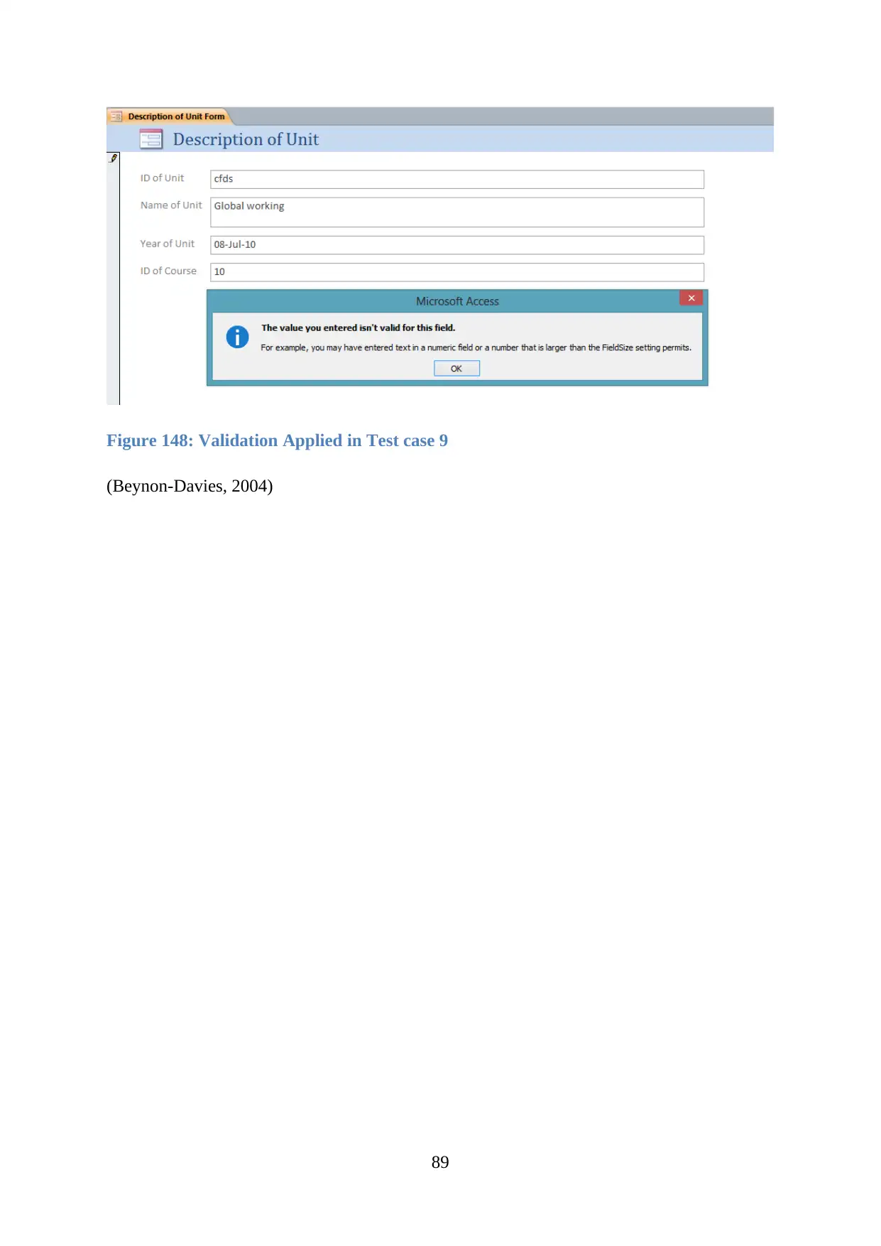
Figure 148: Validation Applied in Test case 9
(Beynon-Davies, 2004)
89
(Beynon-Davies, 2004)
89
4.3 Create user documentation for a developed relational database system
User Documentation
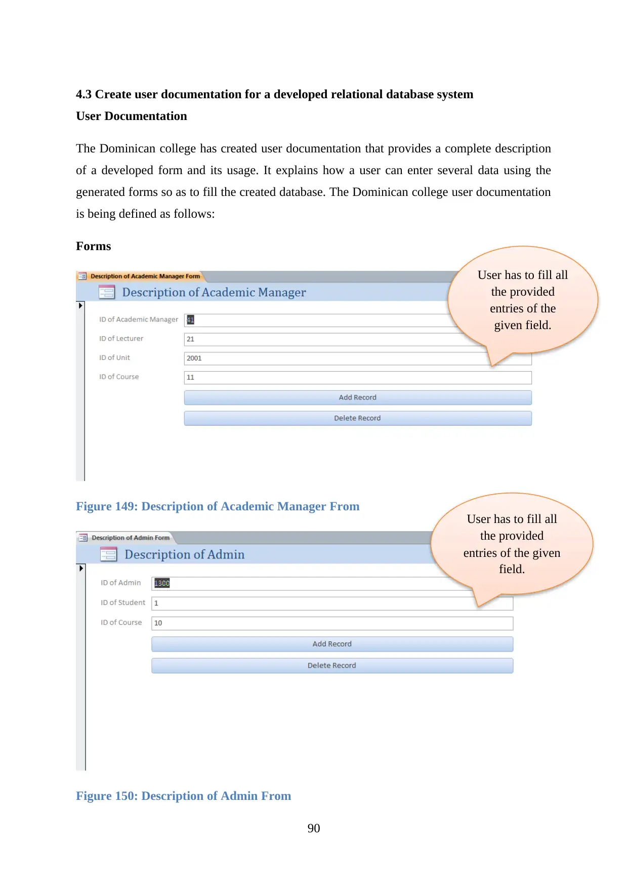
The Dominican college has created user documentation that provides a complete description
of a developed form and its usage. It explains how a user can enter several data using the
generated forms so as to fill the created database. The Dominican college user documentation
is being defined as follows:
Forms
Figure 149: Description of Academic Manager From
Figure 150: Description of Admin From
90
User has to fill all
the provided
entries of the
given field.
User has to fill all
the provided
entries of the given
field.

Figure 151: Description of Campus From
Figure 152: Description of Course From
91
User has to fill all
the provided
entries of the
given field.
User has to fill all
the provided
entries of the
given field.
Figure 152: Description of Course From
91
User has to fill all
the provided
entries of the
given field.
User has to fill all
the provided
entries of the
given field.
Paraphrase This Document
Need a fresh take? Get an instant paraphrase of this document with our AI Paraphraser
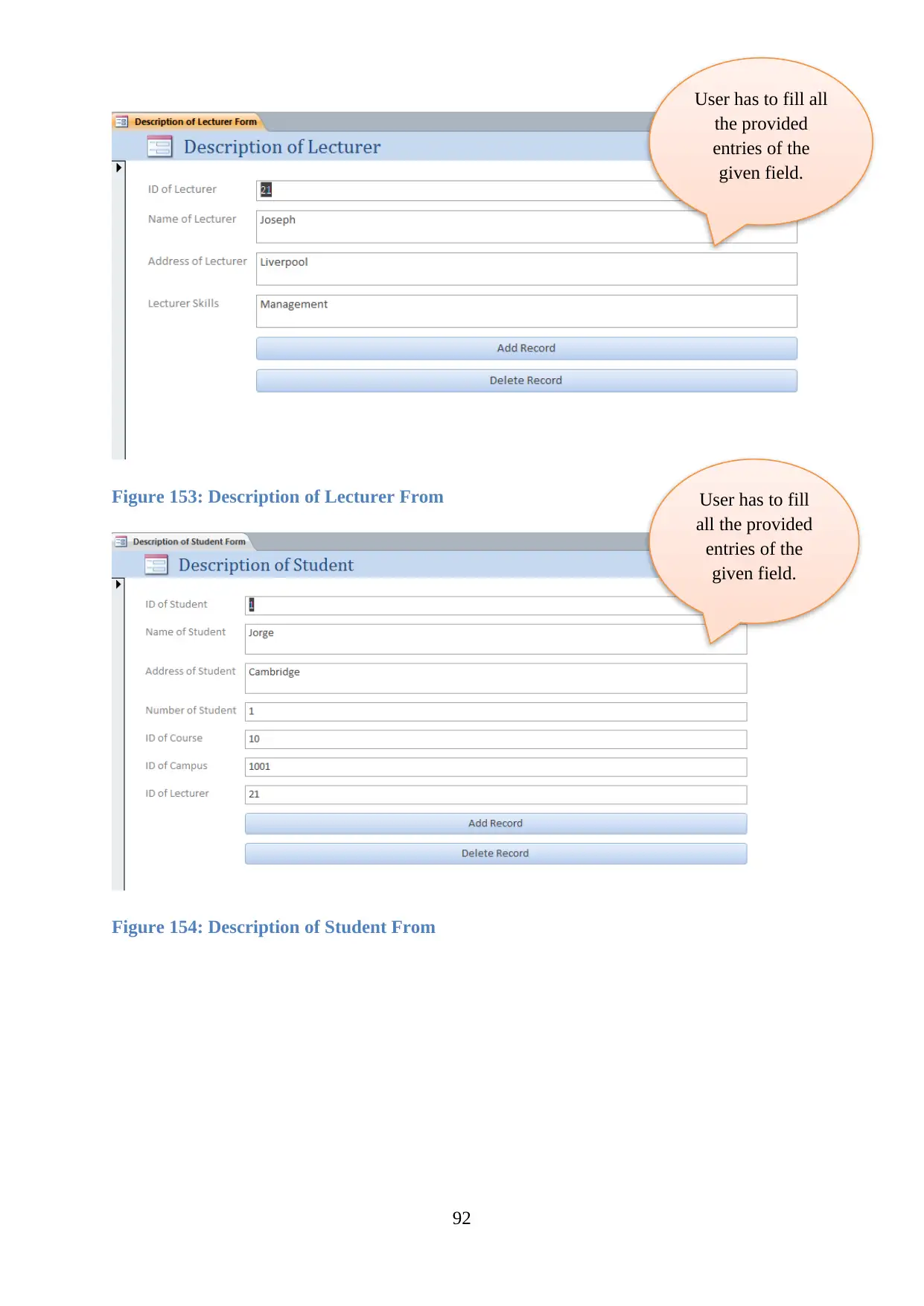
Figure 153: Description of Lecturer From
Figure 154: Description of Student From
92
User has to fill all
the provided
entries of the
given field.
User has to fill
all the provided
entries of the
given field.
Figure 154: Description of Student From
92
User has to fill all
the provided
entries of the
given field.
User has to fill
all the provided
entries of the
given field.
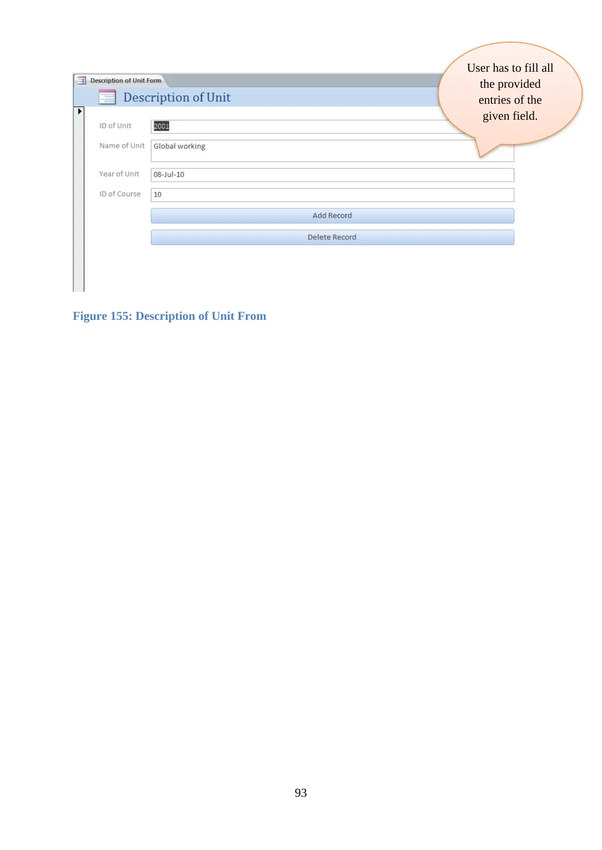
Figure 155: Description of Unit From
93
User has to fill all
the provided
entries of the
given field.
93
User has to fill all
the provided
entries of the
given field.

4.4 Explain how verification and validation has been addressed
Verification and Validation
Verification is a process where SDLC phase is developed and analysed properly to determine
whether all desires of the user are fulfilled. The created forms are being verified and properly
evaluated according to the respective field type.
Validation is a process that considers justification of those generated validations in
accordance with the desires of the user. This particular process completely satisfies all desires
of customers in accordance to the created database. This particular phase includes the
technology of dynamic testing (Teorey, Lightstone, Nadeau and Jagadish, 2011).
Some of the validations of Dominican college are being provided below:
Figure 156: Validation Applied in Test case 1
94
Secure Best Marks with AI Grader
Need help grading? Try our AI Grader for instant feedback on your assignments.
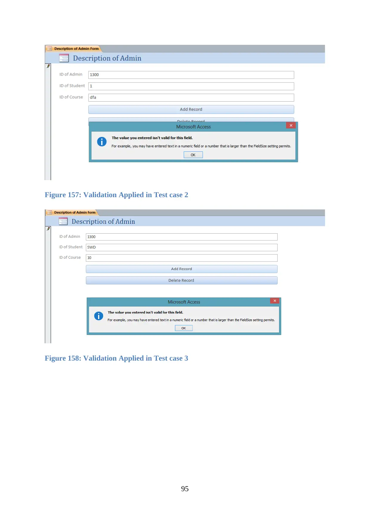
Figure 157: Validation Applied in Test case 2
Figure 158: Validation Applied in Test case 3
95
Figure 158: Validation Applied in Test case 3
95

Figure 159: Validation Applied in Test case 4
Figure 160: Validation Applied in Test case 5
96
Figure 160: Validation Applied in Test case 5
96

Figure 161: Validation Applied in Test case 6
Figure 162: Validation Applied in Test case 7
97
Figure 162: Validation Applied in Test case 7
97
Paraphrase This Document
Need a fresh take? Get an instant paraphrase of this document with our AI Paraphraser

Figure 163: Validation Applied in Test case 8
Figure 164: Validation Applied in Test case 9
98
Figure 164: Validation Applied in Test case 9
98
4.5 Explain how control mechanisms have been used
Control mechanism comes out to be the crucial part of any organization as the managers as
well as the company directly depends on it. Various tools used in control based mechanism
used to help all organizations in enhancing its process of decision making and its
performance and even helps in fulfilling their goals.
The college named as Dominican wants to develop a database for it using the MS Access. Its
complete implementation takes almost 15 Days in MS Access. The budgets of the user
according to their desires are even considered.
Several control mechanism are being used in the creation of a database for Dominican college
that are:
Bureaucratic control
Personal controls
Output Control
Cultural controls
Many other approaches are even being used regarding the control based mechanism for the
database developed for
Rules approach
Market approach
Corporate culture Approach
Reporting culture (Powell, 2006)
99
Conclusion
The entire report for the developed database of the Dominican college is completed
productively. In the above report, the created database on MS Access is developed using
tables, queries, reports and forms. Several techniques are even used for database
implementation. Different schemes of the database are defined in order to develop models of
the database.
In section two the database created is further implemented and various test cases are provided
along with user and technical documentation. The created database for Dominican college
contains different database validations.
100
Secure Best Marks with AI Grader
Need help grading? Try our AI Grader for instant feedback on your assignments.

References
Abadi, D.J., Boncz, P.A. and Harizopoulos, S., 2009. Column-oriented database
systems. Proceedings of the VLDB Endowment, 2(2), pp.1664-1665.
Beynon-Davies, P., 2004. Database systems (p. 61). Basingstoke, UK: Palgrave
Macmillan.
Date, C.J., 2006. An introduction to database systems. Pearson Education India.
Elmasri, R., 2008. Fundamentals of database systems. Pearson Education India.
Garcia-Molina, H., 2008. Database systems: the complete book. Pearson Education India.
Hardavellas, N., Pandis, I., Johnson, R., Mancheril, N., Ailamaki, A. and Falsafi, B.,
2007. Database servers on chip multiprocessors: Limitations and opportunities.
In Proceedings of the Biennial Conference on Innovative Data Systems Research (No.
DIAS-CONF-2007-008).
Huber, V.J., Wang Laboratories Inc, 1990. Relational database system. U.S. Patent
4,918,593.
Powell, G., 2006. Beginning database design. John Wiley & Sons.
Teorey, T.J., Lightstone, S.S., Nadeau, T. and Jagadish, H.V., 2011. Database modeling
and design: logical design. Elsevier.
101

Appendix
102
102
1 out of 102
Related Documents
Your All-in-One AI-Powered Toolkit for Academic Success.
+13062052269
info@desklib.com
Available 24*7 on WhatsApp / Email
![[object Object]](/_next/static/media/star-bottom.7253800d.svg)
Unlock your academic potential
© 2024 | Zucol Services PVT LTD | All rights reserved.


