Relational Database System Design & Development for VET Solutions
VerifiedAdded on 2024/05/21
|44
|3882
|307
Project
AI Summary
This project focuses on the design and development of a relational database system for VET Solutions, a veterinary company. The project begins with designing the database using appropriate tools and techniques, including ER diagrams and data dictionaries. It covers data integrity through validation and normalization to reduce redundancy. The database is then developed and implemented using MS SQL Server, creating tables, relationships, and implementing data types. Query languages are produced to retrieve and manage information across multiple tables, generating management information. The system undergoes thorough testing with a comprehensive test plan to ensure it meets user and system requirements. Finally, user and technical documentation is provided, detailing the database structure, queries, and system functionalities. The goal is to create a reliable and efficient database system to enhance communication and data management within VET Solutions.
Database Design and Development
1
1
Paraphrase This Document
Need a fresh take? Get an instant paraphrase of this document with our AI Paraphraser
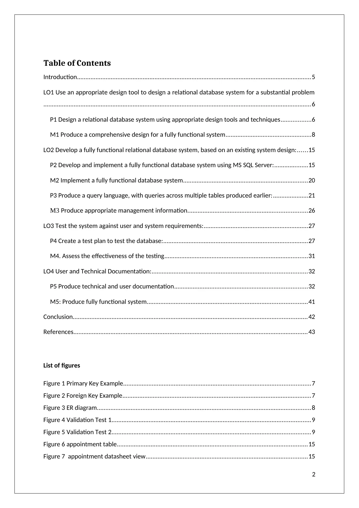
Table of Contents
Introduction...........................................................................................................................................5
LO1 Use an appropriate design tool to design a relational database system for a substantial problem
...............................................................................................................................................................6
P1 Design a relational database system using appropriate design tools and techniques..................6
M1 Produce a comprehensive design for a fully functional system...................................................8
LO2 Develop a fully functional relational database system, based on an existing system design:......15
P2 Develop and implement a fully functional database system using MS SQL Server:....................15
M2 Implement a fully functional database system..........................................................................20
P3 Produce a query language, with queries across multiple tables produced earlier:.....................21
M3 Produce appropriate management information.......................................................................26
LO3 Test the system against user and system requirements:..............................................................27
P4 Create a test plan to test the database:......................................................................................27
M4. Assess the effectiveness of the testing.....................................................................................31
LO4 User and Technical Documentation:............................................................................................32
P5 Produce technical and user documentation...............................................................................32
M5: Produce fully functional system...............................................................................................41
Conclusion...........................................................................................................................................42
References...........................................................................................................................................43
List of figures
Figure 1 Primary Key Example...............................................................................................................7
Figure 2 Foreign Key Example................................................................................................................7
Figure 3 ER diagram...............................................................................................................................8
Figure 4 Validation Test 1......................................................................................................................9
Figure 5 Validation Test 2......................................................................................................................9
Figure 6 appointment table.................................................................................................................15
Figure 7 appointment datasheet view................................................................................................15
2
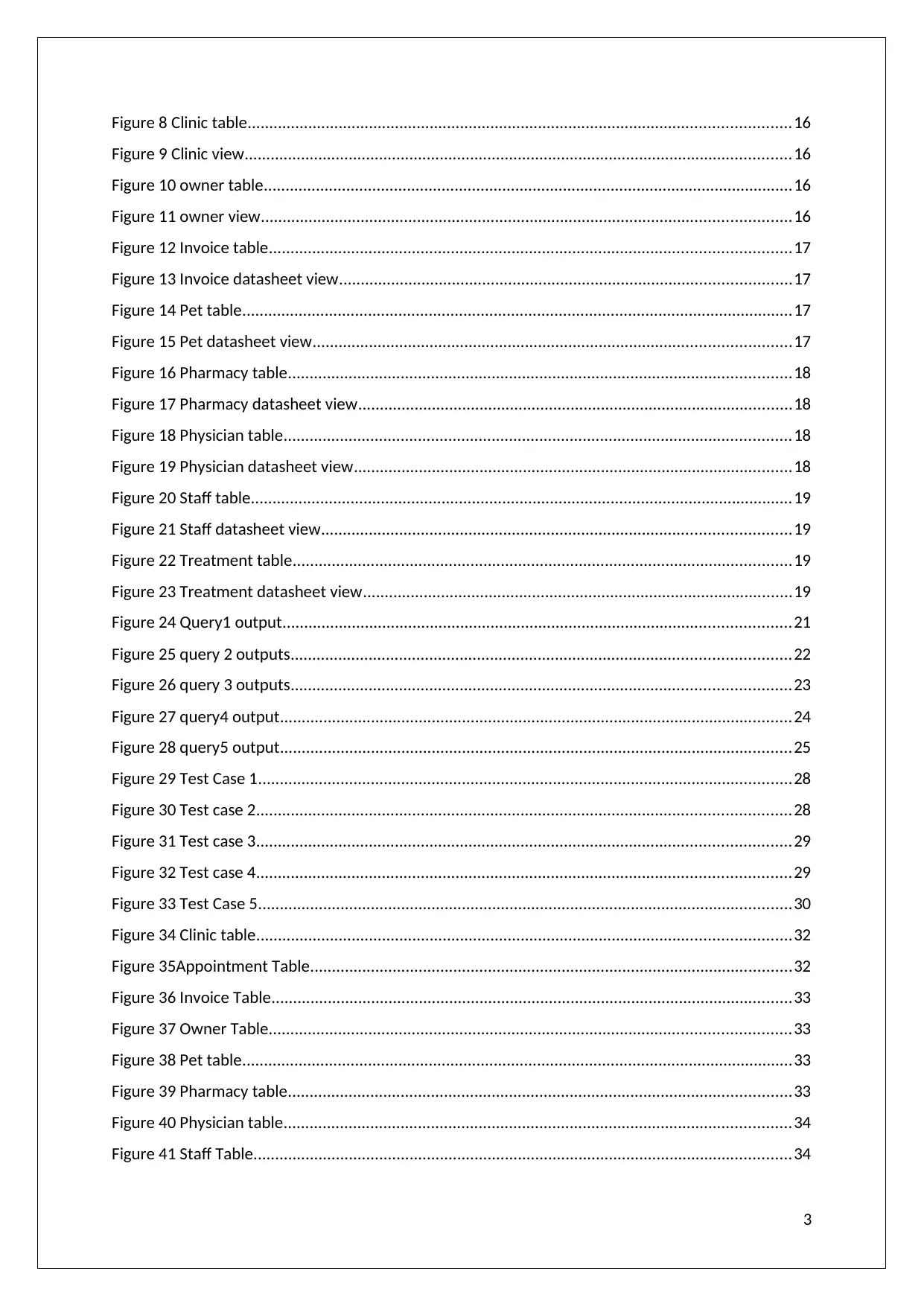
Figure 8 Clinic table.............................................................................................................................16
Figure 9 Clinic view..............................................................................................................................16
Figure 10 owner table..........................................................................................................................16
Figure 11 owner view..........................................................................................................................16
Figure 12 Invoice table........................................................................................................................17
Figure 13 Invoice datasheet view........................................................................................................17
Figure 14 Pet table...............................................................................................................................17
Figure 15 Pet datasheet view..............................................................................................................17
Figure 16 Pharmacy table....................................................................................................................18
Figure 17 Pharmacy datasheet view....................................................................................................18
Figure 18 Physician table.....................................................................................................................18
Figure 19 Physician datasheet view.....................................................................................................18
Figure 20 Staff table.............................................................................................................................19
Figure 21 Staff datasheet view............................................................................................................19
Figure 22 Treatment table...................................................................................................................19
Figure 23 Treatment datasheet view...................................................................................................19
Figure 24 Query1 output.....................................................................................................................21
Figure 25 query 2 outputs...................................................................................................................22
Figure 26 query 3 outputs...................................................................................................................23
Figure 27 query4 output......................................................................................................................24
Figure 28 query5 output......................................................................................................................25
Figure 29 Test Case 1...........................................................................................................................28
Figure 30 Test case 2...........................................................................................................................28
Figure 31 Test case 3...........................................................................................................................29
Figure 32 Test case 4...........................................................................................................................29
Figure 33 Test Case 5...........................................................................................................................30
Figure 34 Clinic table...........................................................................................................................32
Figure 35Appointment Table...............................................................................................................32
Figure 36 Invoice Table........................................................................................................................33
Figure 37 Owner Table........................................................................................................................33
Figure 38 Pet table...............................................................................................................................33
Figure 39 Pharmacy table....................................................................................................................33
Figure 40 Physician table.....................................................................................................................34
Figure 41 Staff Table............................................................................................................................34
3
⊘ This is a preview!⊘
Do you want full access?
Subscribe today to unlock all pages.

Trusted by 1+ million students worldwide
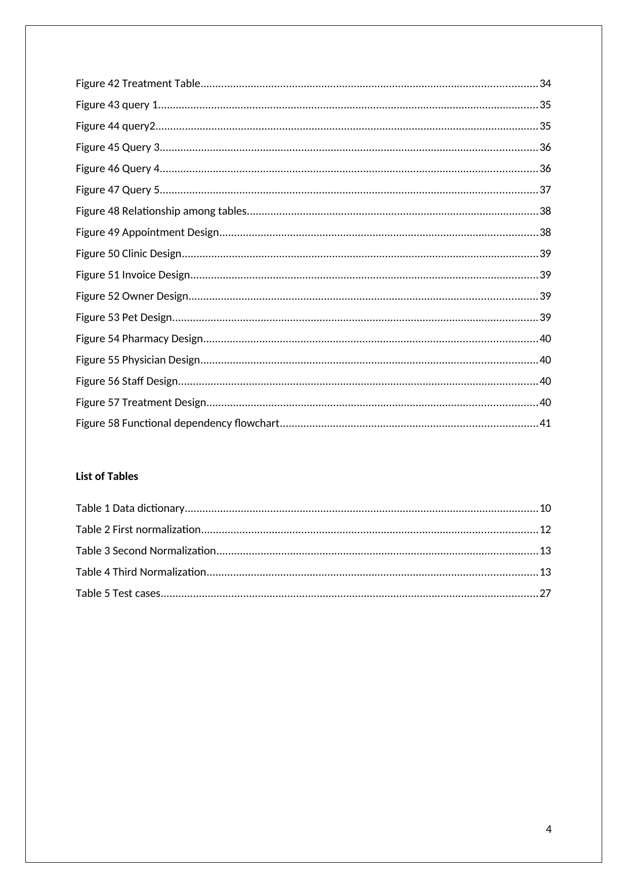
Figure 42 Treatment Table..................................................................................................................34
Figure 43 query 1.................................................................................................................................35
Figure 44 query2..................................................................................................................................35
Figure 45 Query 3................................................................................................................................36
Figure 46 Query 4................................................................................................................................36
Figure 47 Query 5................................................................................................................................37
Figure 48 Relationship among tables...................................................................................................38
Figure 49 Appointment Design............................................................................................................38
Figure 50 Clinic Design.........................................................................................................................39
Figure 51 Invoice Design......................................................................................................................39
Figure 52 Owner Design......................................................................................................................39
Figure 53 Pet Design............................................................................................................................39
Figure 54 Pharmacy Design.................................................................................................................40
Figure 55 Physician Design..................................................................................................................40
Figure 56 Staff Design..........................................................................................................................40
Figure 57 Treatment Design................................................................................................................40
Figure 58 Functional dependency flowchart.......................................................................................41
List of Tables
Table 1 Data dictionary........................................................................................................................10
Table 2 First normalization..................................................................................................................12
Table 3 Second Normalization.............................................................................................................13
Table 4 Third Normalization................................................................................................................13
Table 5 Test cases................................................................................................................................27
4
Paraphrase This Document
Need a fresh take? Get an instant paraphrase of this document with our AI Paraphraser
Introduction
In this project, I will be working on designing and development of a database management
system for a veteran company VET SOLUTION in Cambridgeshire to create an effective
communication between all the branches of the company can be made. The design of the
database system has been made as per company’s requirements which reduce their time
consumption in manual updation and it is reliable in case of a fault.
The database management system, after its designing and development, has been properly
implemented and tested and has been discussed in this report.
5
LO1 Use an appropriate design tool to design a relational database system
for a substantial problem
P1 Design a relational database system using appropriate design tools and
techniques
Specifications of Database System and its Role: - System of Database is used to manage
whole data within a company by storing huge amounts of data in software application using
relational tables. It decreases data redundancy and presents data in a convincing manner that
helps in efficient decision making. It improves the performance of a system and provides
advance built-in analysis functionalities.
Tools and Techniques for Relational Database
Relational Database is the most common type of DBMS. In this, data is stored in tables. A
tool used for formatting data in tables is MS SQL Server. It is also known as Standard Query
Language.
Logical Design for Relational Database:-
To make a relational database, it should first be logically designed. A database consists of an
entity, its attribute, and relationship among entities. Each entity should have a primary key.
ER- Diagram
Pictorial representation of relationships shared among various entities.
Entity- An entity is an object of the database which stores a primary key. It is represented by
a rectangle.
Attribute: - Attributes are the values that define an entity. It is represented by Oval.
Relationship: - Relationship shows how two entities share information in a database. It is
represented by Diamond.
Data Elements: - Data Elements contains the attribute of an entity. It can be of any data type
and its length can be specified while developing a database.
Data Types: - Data type defines what type of variable a data can store like character, integer,
or Boolean value.
Indexes: - Indices are the location of a row of data. In the table, it acts as a pointer.
Primary/Foreign Key: - A unique column in the table is known as a primary key that is used
to separate a row in the table from any other row and when the primary key of one table is
applied in another table for reference then it becomes Foreign Key.
6
⊘ This is a preview!⊘
Do you want full access?
Subscribe today to unlock all pages.

Trusted by 1+ million students worldwide
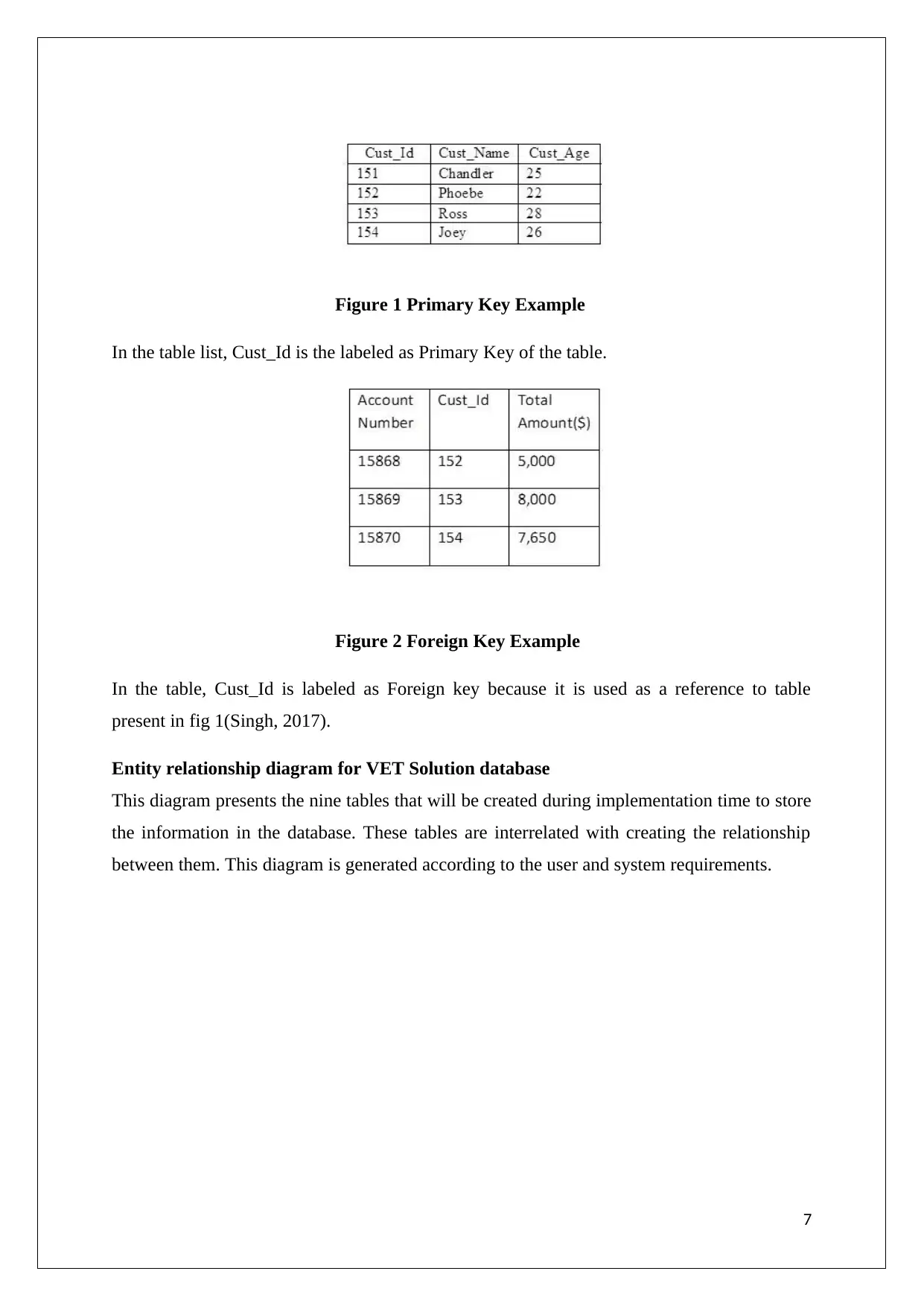
Figure 1 Primary Key Example
In the table list, Cust_Id is the labeled as Primary Key of the table.
Figure 2 Foreign Key Example
In the table, Cust_Id is labeled as Foreign key because it is used as a reference to table
present in fig 1(Singh, 2017).
Entity relationship diagram for VET Solution database
This diagram presents the nine tables that will be created during implementation time to store
the information in the database. These tables are interrelated with creating the relationship
between them. This diagram is generated according to the user and system requirements.
7
Paraphrase This Document
Need a fresh take? Get an instant paraphrase of this document with our AI Paraphraser
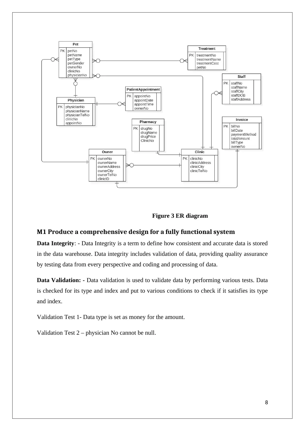
Figure 3 ER diagram
M1 Produce a comprehensive design for a fully functional system
Data Integrity: - Data Integrity is a term to define how consistent and accurate data is stored
in the data warehouse. Data integrity includes validation of data, providing quality assurance
by testing data from every perspective and coding and processing of data.
Data Validation: - Data validation is used to validate data by performing various tests. Data
is checked for its type and index and put to various conditions to check if it satisfies its type
and index.
Validation Test 1- Data type is set as money for the amount.
Validation Test 2 – physician No cannot be null.
8
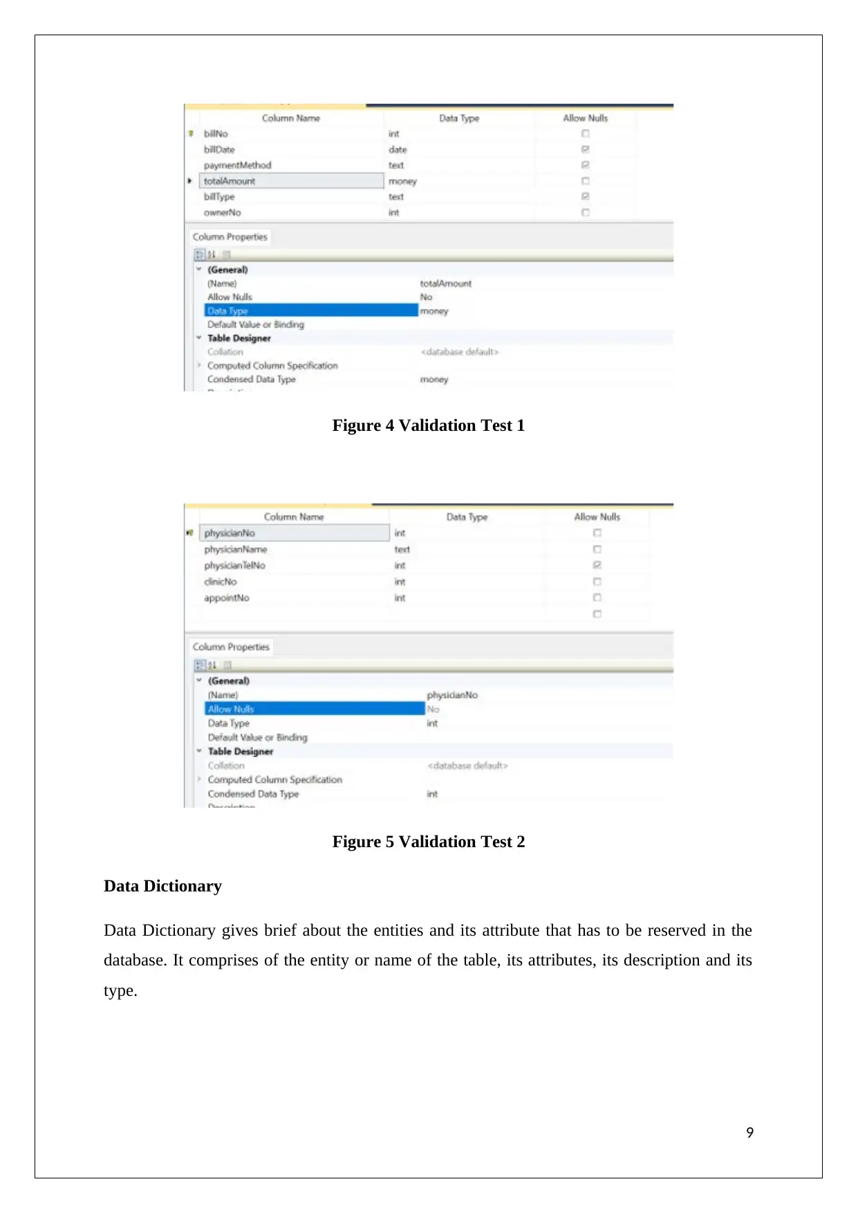
Figure 4 Validation Test 1
Figure 5 Validation Test 2
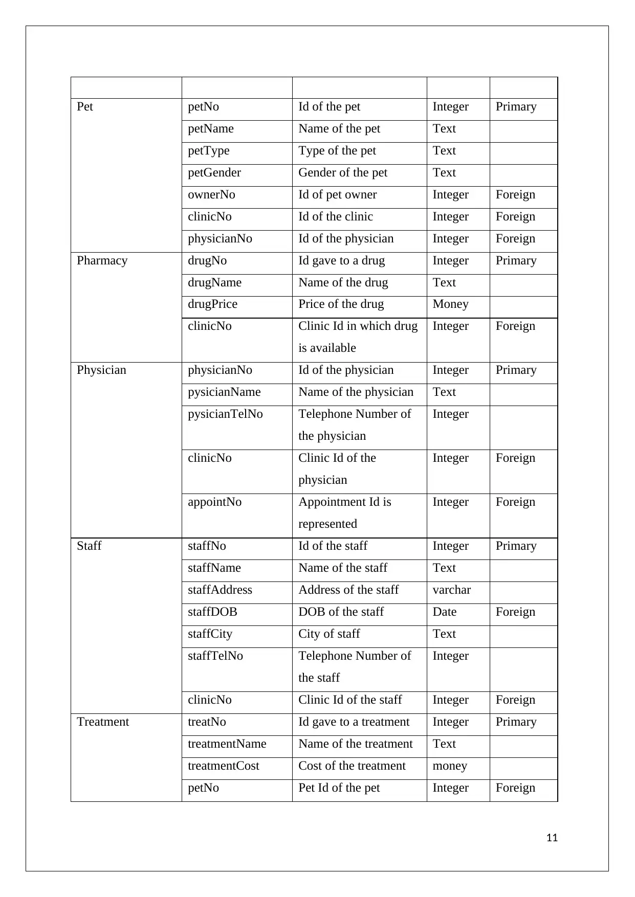
Data Dictionary
Data Dictionary gives brief about the entities and its attribute that has to be reserved in the
database. It comprises of the entity or name of the table, its attributes, its description and its
type.
9
Figure 5 Validation Test 2
Data Dictionary
Data Dictionary gives brief about the entities and its attribute that has to be reserved in the
database. It comprises of the entity or name of the table, its attributes, its description and its
type.
9
⊘ This is a preview!⊘
Do you want full access?
Subscribe today to unlock all pages.

Trusted by 1+ million students worldwide
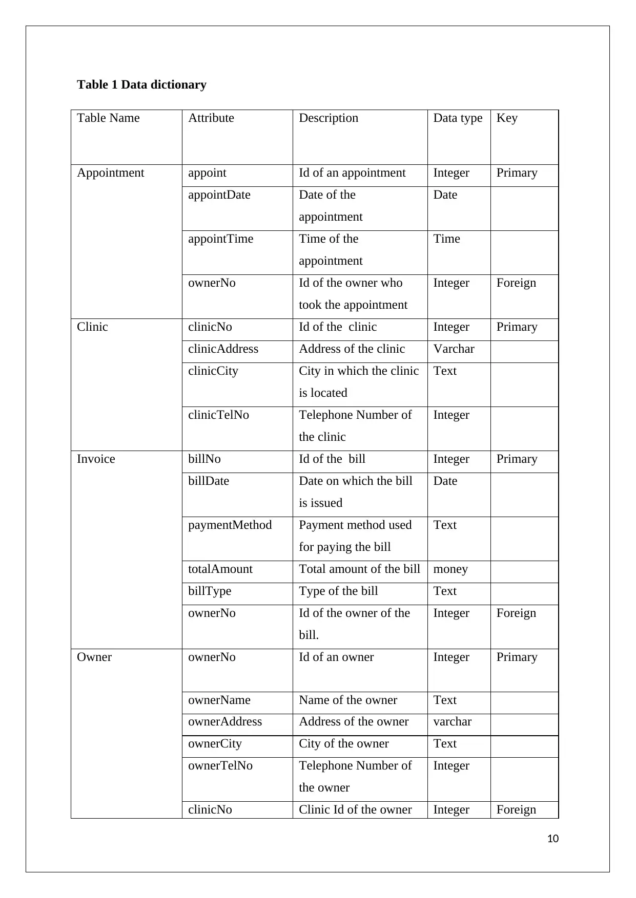
Table 1 Data dictionary
Table Name Attribute Description Data type Key
Appointment appoint Id of an appointment Integer Primary
appointDate Date of the
appointment
Date
appointTime Time of the
appointment
Time
ownerNo Id of the owner who
took the appointment
Integer Foreign
Clinic clinicNo Id of the clinic Integer Primary
clinicAddress Address of the clinic Varchar
clinicCity City in which the clinic
is located
Text
clinicTelNo Telephone Number of
the clinic
Integer
Invoice billNo Id of the bill Integer Primary
billDate Date on which the bill
is issued
Date
paymentMethod Payment method used
for paying the bill
Text
totalAmount Total amount of the bill money
billType Type of the bill Text
ownerNo Id of the owner of the
bill.
Integer Foreign
Owner ownerNo Id of an owner Integer Primary
ownerName Name of the owner Text
ownerAddress Address of the owner varchar
ownerCity City of the owner Text
ownerTelNo Telephone Number of
the owner
Integer
clinicNo Clinic Id of the owner Integer Foreign
10
Paraphrase This Document
Need a fresh take? Get an instant paraphrase of this document with our AI Paraphraser
Pet petNo Id of the pet Integer Primary
petName Name of the pet Text
petType Type of the pet Text
petGender Gender of the pet Text
ownerNo Id of pet owner Integer Foreign
clinicNo Id of the clinic Integer Foreign
physicianNo Id of the physician Integer Foreign
Pharmacy drugNo Id gave to a drug Integer Primary
drugName Name of the drug Text
drugPrice Price of the drug Money
clinicNo Clinic Id in which drug
is available
Integer Foreign
Physician physicianNo Id of the physician Integer Primary
pysicianName Name of the physician Text
pysicianTelNo Telephone Number of
the physician
Integer
clinicNo Clinic Id of the
physician
Integer Foreign
appointNo Appointment Id is
represented
Integer Foreign
Staff staffNo Id of the staff Integer Primary
staffName Name of the staff Text
staffAddress Address of the staff varchar
staffDOB DOB of the staff Date Foreign
staffCity City of staff Text
staffTelNo Telephone Number of
the staff
Integer
clinicNo Clinic Id of the staff Integer Foreign
Treatment treatNo Id gave to a treatment Integer Primary
treatmentName Name of the treatment Text
treatmentCost Cost of the treatment money
petNo Pet Id of the pet Integer Foreign
11
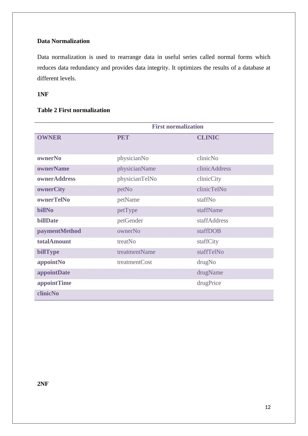
Data Normalization
Data normalization is used to rearrange data in useful series called normal forms which
reduces data redundancy and provides data integrity. It optimizes the results of a database at
different levels.
1NF
Table 2 First normalization
First normalization
OWNER PET CLINIC
ownerNo physicianNo clinicNo
ownerName physicianName clinicAddress
ownerAddress physicianTelNo clinicCity
ownerCity petNo clinicTelNo
ownerTelNo petName staffNo
billNo petType staffName
billDate petGender staffAddress
paymentMethod ownerNo staffDOB
totalAmount treatNo staffCity
billType treatmentName staffTelNo
appointNo treatmentCost drugNo
appointDate drugName
appointTime drugPrice
clinicNo
2NF
12
⊘ This is a preview!⊘
Do you want full access?
Subscribe today to unlock all pages.

Trusted by 1+ million students worldwide
1 out of 44
Related Documents
Your All-in-One AI-Powered Toolkit for Academic Success.
+13062052269
info@desklib.com
Available 24*7 on WhatsApp / Email
![[object Object]](/_next/static/media/star-bottom.7253800d.svg)
Unlock your academic potential
Copyright © 2020–2026 A2Z Services. All Rights Reserved. Developed and managed by ZUCOL.


