P a g e|1 Table of contents Assumptions...............................................................................................................................2 Logical ER diagram.....................................................................................................................3 Physical ER diagram...................................................................................................................4 Data Dictionary...........................................................................................................................5 1
P a g e|2 Assumptions ï‚·The customers who are registered, only their details are recorded. ï‚·Each customer has their addresses. Customers can have multiple addresses. ï‚·All the customer details are mandatory. ï‚·The customer referral number will be from the customer table. ï‚·Except for address name, all the address tables are mandatory. ï‚·The items which are registered, only their details are recorded in the database. ï‚·It is not mandatory to the description of each item. ï‚·Each item belongs at least one category. ï‚·Each order has a particular invoice number. ï‚·It is possible the customer has never ordered anything. ï‚·It is possible that particular item has never been ordered. ï‚·It is possible that particular category has never been ordered. ï‚·It is possible that customer has not been interested in any of the categories. 2
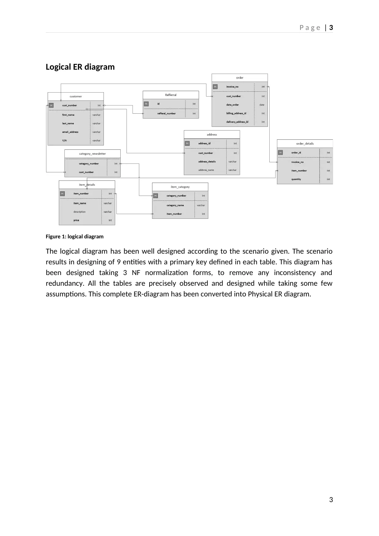
P a g e|3 Logical ER diagram Figure1: logical diagram The logical diagram has been well designed according to the scenario given. The scenario results in designing of 9 entities with a primary key defined in each table. This diagram has beendesignedtaking3NFnormalizationforms,toremoveanyinconsistencyand redundancy. All the tables are precisely observed and designed while taking some few assumptions. This complete ER-diagram has been converted into Physical ER diagram. 3
Paraphrase This Document
Need a fresh take? Get an instant paraphrase of this document with our AI Paraphraser
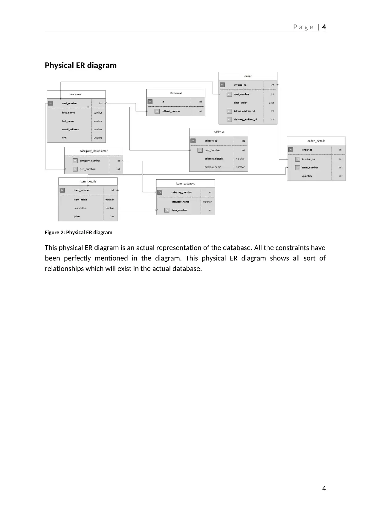
P a g e|4 Physical ER diagram Figure2: Physical ER diagram This physical ER diagram is an actual representation of the database. All the constraints have been perfectly mentioned in the diagram. This physical ER diagram shows all sort of relationships which will exist in the actual database. 4
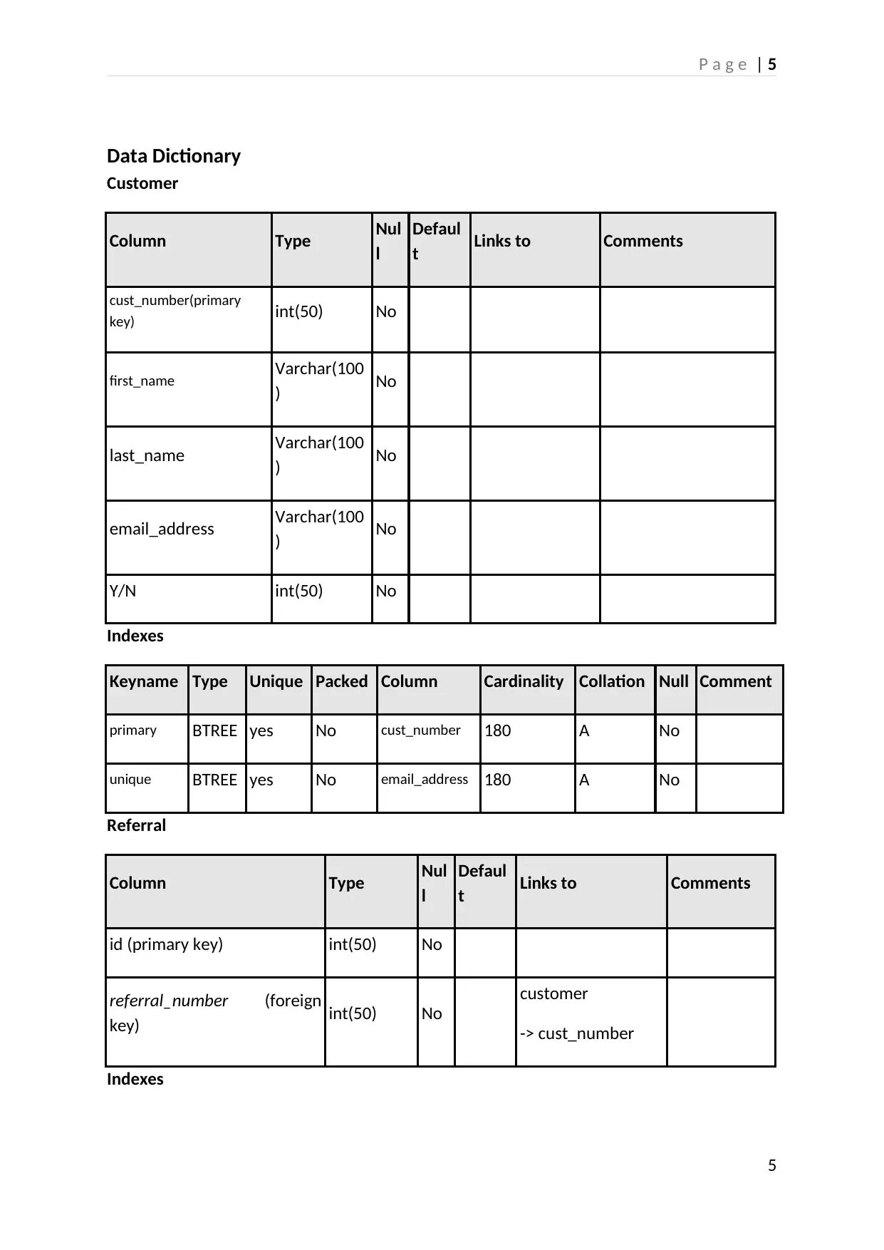
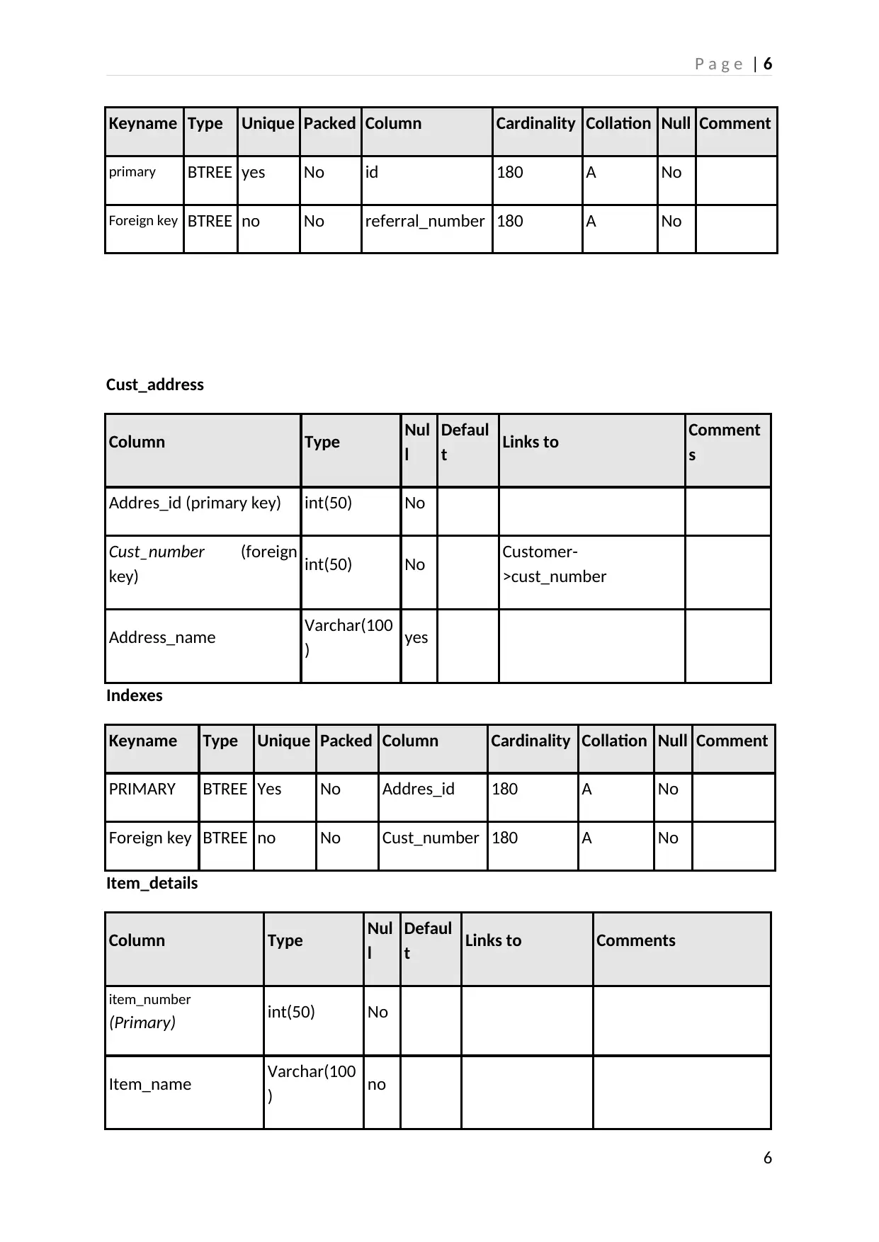
P a g e|5 Data Dictionary Customer ColumnTypeNul l Defaul tLinks toComments cust_number(primary key)int(50)No first_nameVarchar(100 )No last_nameVarchar(100 )No email_addressVarchar(100 )No Y/Nint(50)No Indexes KeynameTypeUniquePackedColumnCardinalityCollationNullComment primaryBTREEyesNocust_number180ANo uniqueBTREEyesNoemail_address180ANo Referral ColumnTypeNul l Defaul tLinks toComments id (primary key)int(50)No referral_number(foreign key)int(50)No customer -> cust_number Indexes 5
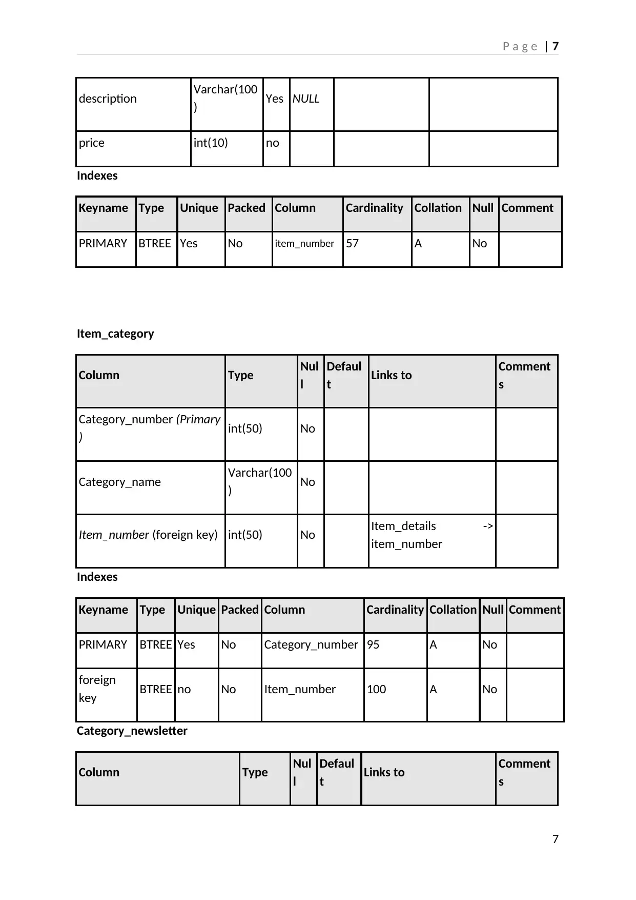
P a g e|6 KeynameTypeUniquePackedColumnCardinalityCollationNullComment primaryBTREEyesNoid180ANo Foreign keyBTREEnoNoreferral_number180ANo Cust_address ColumnTypeNul l Defaul tLinks toComment s Addres_id (primary key)int(50)No Cust_number(foreign key)int(50)NoCustomer- >cust_number Address_nameVarchar(100 )yes Indexes KeynameTypeUniquePackedColumnCardinalityCollationNullComment PRIMARYBTREEYesNoAddres_id180ANo Foreign keyBTREEnoNoCust_number180ANo Item_details ColumnTypeNul l Defaul tLinks toComments item_number (Primary)int(50)No Item_nameVarchar(100 )no 6
Secure Best Marks with AI Grader
Need help grading? Try our AI Grader for instant feedback on your assignments.