Database Implementation
38 Pages5094 Words79 Views
Added on 2022-12-28
About This Document
This document discusses the process of database implementation, including design, configuration, and integration. It explores the concept of entity relationship modeling and provides an example of an ER diagram. The document also covers the normalization process and the use of database management systems in implementing a solution. It concludes with a discussion on denormalization and its circumstances.
Database Implementation
Added on 2022-12-28
ShareRelated Documents
Database Implementation
1
1

Contents
INTRODUCTION...........................................................................................................................3
TASK...............................................................................................................................................4
CONCLUSION..............................................................................................................................36
RECOMMENDATION.................................................................................................................36
REFERENCES..............................................................................................................................38
2
INTRODUCTION
Database implementation is based on the process or method of installation of database
software, configuration, running, customization and integrating with different applications.
Database design is a collection of different process that provide the better facilities in term of
designing, development, implementation as well as maintenance of enterprise data. Usually, it
will designed a database which become easier to maintain and improve data consistency. These
are become as cost effective in storage of data within disk space. The purpose of database design
is to produce both physical as well as logical design model and then proposed as new database
system.
In this report, it is mainly focused on the case scenario related the “Walk & Wag” enterprise.
This should include all detail about the dog walking to next level by building an online
operation. This documentation will discuss about the data model in the form entity relationship
model. This diagram will help for representing all kind of entities and their attributes. By using
Enhanced ERD, it will produce logical and physical model of ER on the basis of case study.
However, it will discuss about the normalization process such as 3 NF, also explain the De-
normalize process. Moreover, this report will describe about the database management system
and their importance within implementation to propose a better result or outcome. Analysing the
Structure query language (SQL) that will support for performing the different commands and
generate accurate outcome.
3
TASK
Question-1
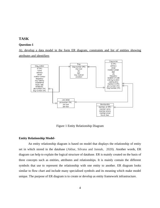
A). develop a data model in the form ER diagram, constraints and list of entities showing
attributes and identifiers
Figure 1 Entity Relationship Diagram
Entity Relationship Model-
An entity relationship diagram is based on model that displays the relationship of entity
set in which stored in the database (Akbar, Silvana and Jannah, 2020). Another words, ER
diagram can help to explain the logical structure of database. ER is mainly created on the basis of
three concepts such as entities, attributes and relationships. It is mainly contain the different
symbols that use to represent the relationship with one entity to another. ER diagram looks
similar to flow chart and include many specialised symbols and its meaning which make model
unique. The purpose of ER diagram is to create or develop as entity framework infrastructure.
4
Question-1
A). develop a data model in the form ER diagram, constraints and list of entities showing
attributes and identifiers
Figure 1 Entity Relationship Diagram
Entity Relationship Model-
An entity relationship diagram is based on model that displays the relationship of entity
set in which stored in the database (Akbar, Silvana and Jannah, 2020). Another words, ER
diagram can help to explain the logical structure of database. ER is mainly created on the basis of
three concepts such as entities, attributes and relationships. It is mainly contain the different
symbols that use to represent the relationship with one entity to another. ER diagram looks
similar to flow chart and include many specialised symbols and its meaning which make model
unique. The purpose of ER diagram is to create or develop as entity framework infrastructure.
4
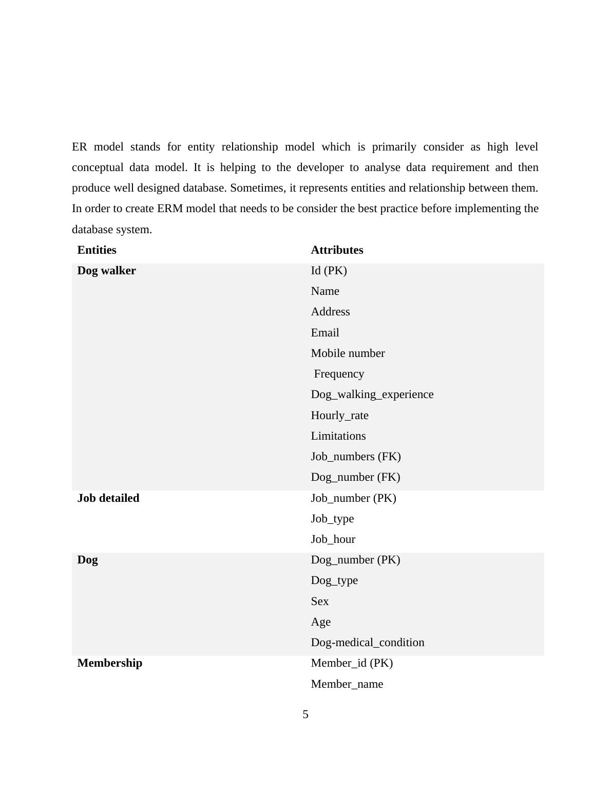
ER model stands for entity relationship model which is primarily consider as high level
conceptual data model. It is helping to the developer to analyse data requirement and then
produce well designed database. Sometimes, it represents entities and relationship between them.
In order to create ERM model that needs to be consider the best practice before implementing the
database system.
Entities Attributes
Dog walker Id (PK)
Name
Address
Email
Mobile number
Frequency
Dog_walking_experience
Hourly_rate
Limitations
Job_numbers (FK)
Dog_number (FK)
Job detailed Job_number (PK)
Job_type
Job_hour
Dog Dog_number (PK)
Dog_type
Sex
Age
Dog-medical_condition
Membership Member_id (PK)
Member_name
5
conceptual data model. It is helping to the developer to analyse data requirement and then
produce well designed database. Sometimes, it represents entities and relationship between them.
In order to create ERM model that needs to be consider the best practice before implementing the
database system.
Entities Attributes
Dog walker Id (PK)
Name
Address
Mobile number
Frequency
Dog_walking_experience
Hourly_rate
Limitations
Job_numbers (FK)
Dog_number (FK)
Job detailed Job_number (PK)
Job_type
Job_hour
Dog Dog_number (PK)
Dog_type
Sex
Age
Dog-medical_condition
Membership Member_id (PK)
Member_name
5
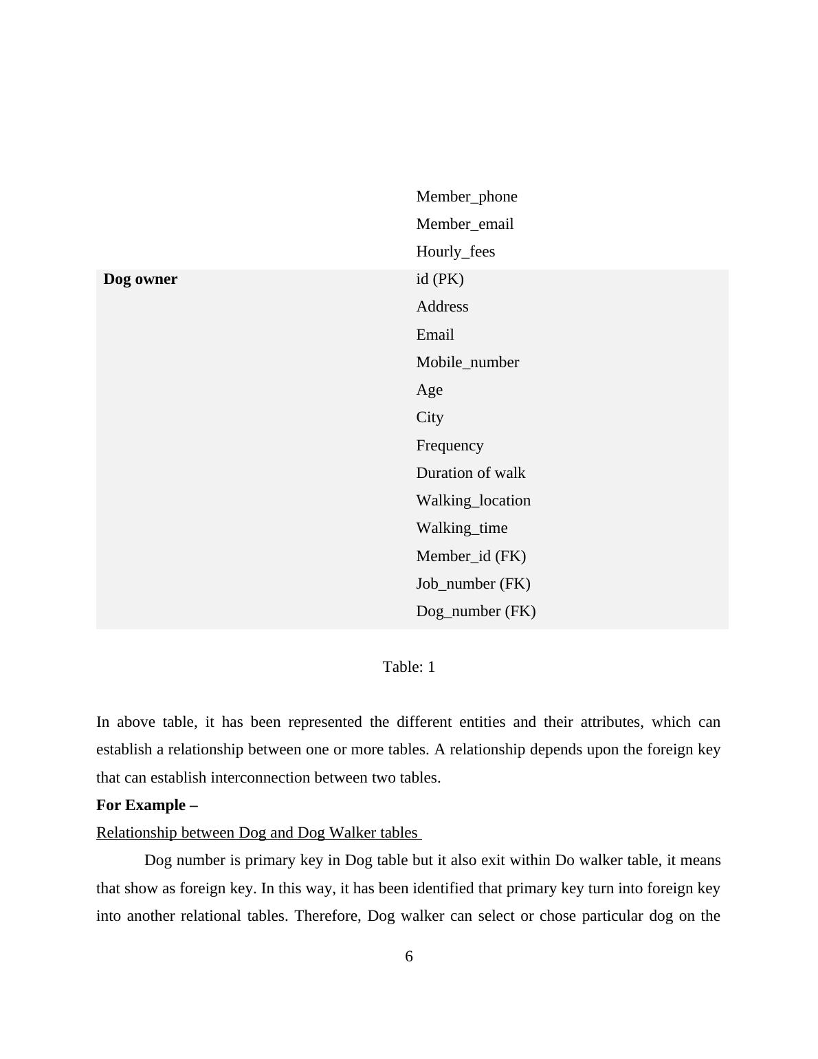
Member_phone
Member_email
Hourly_fees
Dog owner id (PK)
Address
Email
Mobile_number
Age
City
Frequency
Duration of walk
Walking_location
Walking_time
Member_id (FK)
Job_number (FK)
Dog_number (FK)
Table: 1
In above table, it has been represented the different entities and their attributes, which can
establish a relationship between one or more tables. A relationship depends upon the foreign key
that can establish interconnection between two tables.
For Example –
Relationship between Dog and Dog Walker tables
Dog number is primary key in Dog table but it also exit within Do walker table, it means
that show as foreign key. In this way, it has been identified that primary key turn into foreign key
into another relational tables. Therefore, Dog walker can select or chose particular dog on the
6
Member_email
Hourly_fees
Dog owner id (PK)
Address
Mobile_number
Age
City
Frequency
Duration of walk
Walking_location
Walking_time
Member_id (FK)
Job_number (FK)
Dog_number (FK)
Table: 1
In above table, it has been represented the different entities and their attributes, which can
establish a relationship between one or more tables. A relationship depends upon the foreign key
that can establish interconnection between two tables.
For Example –
Relationship between Dog and Dog Walker tables
Dog number is primary key in Dog table but it also exit within Do walker table, it means
that show as foreign key. In this way, it has been identified that primary key turn into foreign key
into another relational tables. Therefore, Dog walker can select or chose particular dog on the
6
basis of preferences. In future, Dog walker has an experience for particular Dog so that it become
easier for selecting themselves.
Relationship between Dog owner and Dog
Dog number is primary key in Dog table but it also exit within Do owner table, it means that
show as foreign key. In this way, it has been identified that primary key turn into foreign key into
another relational tables (Hewasinghage, Abelló and Zimányi, 2020). Therefore, Dog owner can
select a particular dog and also provide the waking services. Sometimes, Dog owner may prefer
to hire or recruit as experienced dog walker to provide better walking services.
Relationship between Dog owner and membership-
Member_id is primary key in membership table but it represent as foreign key into Dog
owner tables. It means that member id can establish as relational between two tables. Therefore,
Dog owner can perform the different tasks, to allocate the particular members for dogs walking
services.
b). Determine the opportunities to use Entity sub-typing concept and develop EERD (Enhanced)
According to the ER Model, there are few entities in data model which may share
common properties or attribute within themselves. On the basis of attributes, it will be
categorised the sub-typing. It is one of subgroup entity and have unique attributes but they will
be stored within different forms.
7
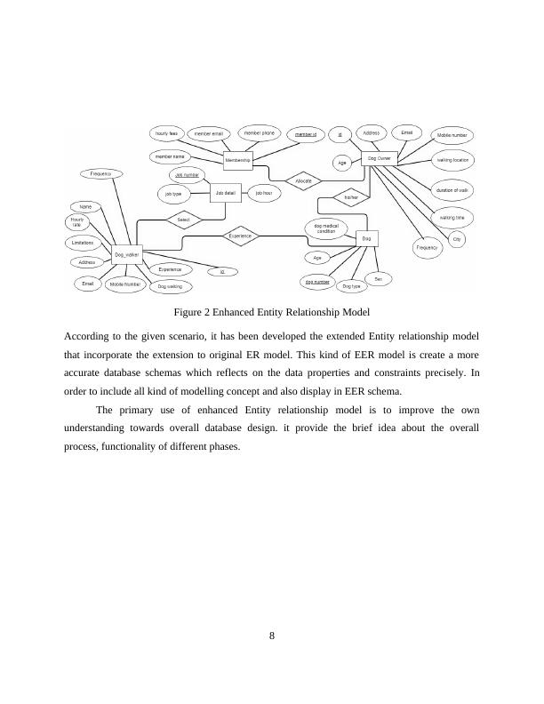
Figure 2 Enhanced Entity Relationship Model
According to the given scenario, it has been developed the extended Entity relationship model
that incorporate the extension to original ER model. This kind of EER model is create a more
accurate database schemas which reflects on the data properties and constraints precisely. In
order to include all kind of modelling concept and also display in EER schema.
The primary use of enhanced Entity relationship model is to improve the own
understanding towards overall database design. it provide the brief idea about the overall
process, functionality of different phases.
8
End of preview
Want to access all the pages? Upload your documents or become a member.
Related Documents
Database and Analytics Principleslg...
|28
|3733
|30
Database Design and Developmentlg...
|20
|2372
|2
Database Management System : Doclg...
|22
|1217
|96
Database Fundamentals: ER Diagram, BCNF, SQL Queries, Optimization, Security, Web Interfacelg...
|23
|2632
|88
BIT358: Advanced Database Assignmentlg...
|10
|1155
|310
Entity Relationship Diagram for Database INTRODUCTION 3 TASKSlg...
|20
|1532
|227